
Related Manuals for MB Connect Line mbNET.mini


Summary of Contents for MB Connect Line mbNET.mini
- Page 1 User Manual User Manual Version: 2.2.1 - EN | Mar 28 Version: 2.2.1 - EN | Mar 28 , 2022 , 2022...
- Page 2 We welcome comments, suggestions for improvement or constructive criticism at any time. SIMPLIFIED EU DECLARATION OF CONFORMITY Hereby, MB connect line GmbH declares that the radio equipment types MDH 862 EU; MDH 863; MDH 866 EU; MDH 867 are in compliance with Directive 2014/53/EU.
-
Page 3: Table Of Contents
Table of contents General..............................6 Safety instructions..........................9 Legal information..........................9 Notes on Cyber-Security........................10 Maintenance............................11 Disposal of old devices........................11 Functional Overview / Specifications....................12 Scope of Supply..........................13 Displays, controls and connections....................15 Interface assignment.......................... 18 10.1 Pinout of the terminal block on the bottom of the device............18 10.2 Pinout of LAN/WAN ports on the front panel of the device............18 10.3 Pinout of the USB port on the front panel of the device............ - Page 4 12.7.1.3.1 WAN device (MDH 860)...................61 12.7.1.3.2 WAN device (MDH 861, 862)...................62 12.7.1.3.3 Wi-Fi device (MDH 863)...................63 12.7.2 Transferring the configuration to mbNET.mini..............64 12.7.2.1 Download configuration to PC - via USB..............65 12.7.2.2 Transfer configuration to the device - via CTM............66 12.7.2.3 Transferring configuration to the device - via mbDIALUP...........
- Page 5 Factory settings on delivery......................122 Loading the factory settings......................122 Firmware update..........................123 17.1 Firmware update via USB......................124 17.2 Firmware update via RSP mbCONNECT24................125 Technical data industrial router mbNET.mini MDH 860 – MDH 867..........127 Table of contents | Page 5 of 131...
-
Page 6: General
Please read carefully and retain this information. Validity of this documentation This manual is valid for the router mbNET.mini MDH 860, MDH 862 EU, MDH 862 AT&T, MDH863, MDH 866 EU, MDH 866 AT&T, MDH 867, from hardware version HW02* with firmware version from V 2.2.0. - Page 7 , 2019 Correction in chapter 11.3 Initial configuration via the device web interface: "You must enter the IP address of the mbNET.mini (192.168.0.253) as the default gateway and as the preferred DNS server." This information is incorrect and has been deleted.
- Page 8 Requests must, where possible, be sent to the following address with the product's serial number: MB connect line GmbH Fernwartungssysteme · Winnettener Str. 6 · 91550 Dinkelsbühl GERMANY Tel. +49 (0) 98 51/58 25 29 0 · Fax +49 (0) 98 51/58 25 29 99 · info@mbconnectline.com...
-
Page 9: Safety Instructions
Proper use The mbNET.mini router may be used only as described in the manual. Disclaimer In this manual all technical information, data and instructions for installation, operation and maintenance are based on our previous experience and insights to the best knowledge. -
Page 10: Notes On Cyber-Security
Notes on Cyber-Security To prevent unauthorized access to facilities and systems, observe the following security recommendations: General • Periodically ensure that all relevant components meet these recommendations and any additional inter- nal security policies. • Perform a security assessment of the entire system. Use a cell protection concept with suitable prod- ucts. -
Page 11: Maintenance
The final holder is responsible for deleting personal data on the old devices to be disposed of. MB connect line offers the possibility of returning and disposing of old devices. Details can be found at www.mbconnectline.com/disposal. -
Page 12: Functional Overview / Specifications
With the function USB over IP the USB port of the mbNET.mini is transmitted or made available direct- ly to the PC of the mbDIALUP user. All devices connected to the USB port of the mbNET.mini (USB memory, PLC, webcams, etc.) are automatically available on this PC. -
Page 13: Scope Of Supply
Scope of Supply Check the package contents for completeness: All device types 1 x mbNET.mini industrial router (Fig. 1 x Quick Start Guide 1 x Device ID card representative) Item No.: 8.002.702.03.00 If one of these parts is missing or MB connect line GmbH Tel.: +49 (0)9851/58 25 29 0... - Page 14 Page 14 von 131 | Version: 2.2.1 - EN | Mar 28 , 2022 |...
-
Page 15: Displays, Controls And Connections
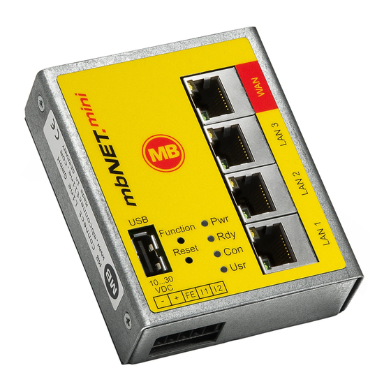
Displays, controls and connections View of front of the device MDH 860 MDH 862 MDH 863 MDH 866 MDH 867 3 x LAN 4 x LAN 4 x LAN 3 x LAN 3 x LAN 1 x WAN 1 x WAN 1 x WAN 4G module Wi-Fi... - Page 16 LED light codes Designation LED-Status Description Device power source is switched off or device is not connected to power Pwr (Power) source/power pack. green Power source is connected to terminal block and switched on. After the system has been checked and started (duration approx. 25 sec), flashing Rdy (Ready) the LED flashes for the duration of the starting up process (approx.
- Page 17 View of bottom of device 0 V DC connection Power source connection 10 - 30 V DC FE Functional earth 1* I/O 1 2* I/O 2 * I/O 1 and I/O 2 can be configured independently of each other as digital input or digital output. View of device from left Device dimensions - mm Antenna connection...
-
Page 18: Interface Assignment
Interface assignment 10.1 Pinout of the terminal block on the bottom of the device 0V DC connection Power source connection 10-30V DC Functional earth Digital Input 1 (10 - 30V DC) Image 1: Terminal strip on the bottom side Digital Output 1 (max. 0.5 A @24 V) Digital Input 1 (10 - 30V DC) Digital Output 1 (max. -
Page 19: Getting Started
The SIM card used must be Internet- / VPN-enabled. If you have any questions, contact your cell phone operator. Connect the mbNET.mini to the power supply NO T I CE Before connecting the device to a network or PC, first ensure that it is properly connected to a power supply, otherwise it may cause damage to other equipment. - Page 20 If you want to forego the support of SIMPLY.connect, ignore the flashing LED Usr and simply continue with the commissioning / configuration of the device. For further support on the mbNET.mini, visit our website on www.mbconnectline.com Page 20 von 131 | Version: 2.2.1 - EN | Mar 28...
-
Page 21: Initial Configuration
Initial configuration Because the mbNET.mini was designed as a portal device, the initial start-up takes place via the web portal. • RSP mbCONNECT24 V 2.x • mbCONNECT24 V 1.x Generally following procedure applies: • Add the mbNET.mini in the portal as a new device. -
Page 22: Initial Configuration Via Rsp Mbconnect24 V 2.0
NENCT24 and how you connect to the portal. Here you can find out how to create a device and perform the initial con- figuration for your mbNET.mini. In this section you will learn the dif- ferent methods, how to transfer the configuration to the mbNET.mini. -
Page 23: Account Request - Software Download
12.1.1 Account request - Software download This chapter describes the steps required to register on the Remote Service Portal mbCONENCT24. 12.1.2 Download mbDIALUP For the registration on the Remote Service Portal mbCONNECT24, you need the remote client software mb- DIALUP. Download the installation package for mbDIALUP free of charge from our download area at www.mbconnectline.com. -
Page 24: Register Your Account For Mbconnect24
12.1.4 Register your account for mbCONNECT24 Start the mbDIALUP program NO T I CE Before starting the registration process, you must select the geographically / strategically more favorable server location for you. Page 24 von 131 | Version: 2.2.1 - EN | Mar 28 , 2022 |... - Page 25 You can choose from the following server locations: • Server location Europe: rsp.mbCONNECT24.net (EU) • Server location USA / Canada: rsp.mbCONNECT24.us (US/CAN) • Server location Asia: rsp.mbCONNECT24.asia (ASIA) • Server location Australia: rsp.au.mbCONNECT24.net (AU) NO T I CE The selected server location can not be changed after registration! Click the "Register new account"...
-
Page 26: "Account Setup
12.1.4.1 1 / 3 "Account Setup" Company name* Input field for the company name. Country* Selection field for the company location. State Input field for the state. Street* Input field for the street. Postal Code* Input field for the postal code. City* Input field for the city. -
Page 27: "Contact Person
12.1.4.2 2 / 3 "Contact Person" Title Selection field for the salutation. First name* Input field for the first name. Last name* Input field for the surname. Business email* Input field for the e-mail address. Repeat business email* Re-enter the e-mail address. NO T I CE The account name is generated from the global part / domain of the e-mail address (john@doefactory.com =>... -
Page 28: "Further Information
12.1.4.3 3 / 3 "Further Information" Your account name will be Here your future account name is displayed. Profile language Selection field for the standard language in your account (the profile lan- guage can be changed at any time later). Account password* Set a password, with high password strength, for your account (see chapter "Notes on Cyber-Security") -
Page 29: Completion Of Registration
NO T I CE The email is sent by "MB connect line", so you can search for it quickly and easily. If it is not in your Inbox, check your other folders. If the email was moved because of a spam filter or an email rule, it could be in the Spam, Advertising, Trash, Deleted Items, or Archive folder. -
Page 30: Connect To Rsp Mbconnect24
12.2 Connect to RSP mbCONNECT24 Selecting the Server 1. Start mbDIALUP and select from the pull-down menu "Server" your mbCONNECT24 server. mbCONNECT24 server list Server name Note mbconnect24.net(EUROPE) mbCONNECT24 V1 - server location: Europe mbconnect24.us(USA/CAN) mbCONNECT24 V1 - server location: USA / Canada rsp.mbCONNECT24.net(EU) RSP mbCONNECT24 V2* - server location: Europe rsp.mbCONNECT24.us(US/CAN) - Page 31 Access via the proxy server If the Internet can only be accessed via a proxy server, the relevant settings can be applied in the menu "Settings", submenu "Port/Proxy settings". Login mbCONNECT24 Log in to the portal with your user data (Username + Password). NO T I CE Your user name has been sent to you by e-mail when registering your mbCONNECT24 user account for.
-
Page 32: Mbconnect24 Configuration
• create a new project • create a new device • generate a configuration file and • transfer it to your mbNET.mini NO T I CE The following description refers to the mbCONNECT24 view mode Extended. You can switch between the two view modes at any time. To do this, click in the footer for "View" on Simple or Advanced. - Page 33 Notice that your password has to fit the password guideline. Your password is active, when you reconnect to the portal. Initial configuration | Page 33 of 131...
-
Page 34: Creating A Project
12.3.2 Creating a project A project is the highest entity to implement the following tasks: • remote maintenance • monitoring and alarming • data-logging • visualization A device (router) is assigned to a project, directly. It is possible to assign several devices to one project. Click the "Administration"... - Page 35 For the basic configuration, it is necessary to fill in the following information: • Number Name* • • Description The tabs „Description“ and „Access“ are necessary for the extended configuration. Term Description Number* Optional field - Input value = alphanumeric Name Mandatory field - Input value = alphanumeric Description...
-
Page 36: Create A New Device
12.3.3 Create a new device After you have defined a Project, it appears following announcement: : "There are no Devices defined in this Project. Click on the button to create your first Device in this Project!" Click on the button „+ Create new Device“. Page 36 von 131 | Version: 2.2.1 - EN | Mar 28 , 2022 |... - Page 37 For the basic configuration, you only need the following data in the tab “Device”. • Device Type Name* • • Description • Serial number The tabs „Description“, „Contact“, „Location“, „Map“ and „Access“ are necessary for the extended configuration. Type Selection field with all device types you can create in the portal. The device type (eg Typ: MDH 834) can be found on the device nameplate, side of the unit.
-
Page 38: Create A Configuration
12.3.4 Create a configuration After you have created a Device, the actual configuration menu appears. For the initial configuration (minimum configuration), only the "Interfaces" widget with the following submenus is relevant. Image 3: Depending on the device type selected, the display may vary here. Click the edit icon to make the settings on the submenus. -
Page 39: Lan Settings
12.3.4.1 LAN Settings Enter a free LAN IP address and the Netmask from your system or machine network. NO T I CE Notice, that the LAN and WAN IP-address should use a different address range. LAN Settings Enter the IP-address of your Device Netmask Enter the Subnet mask where your Device should be integrated. -
Page 40: Wi-Fi Settings
12.3.4.2 Wi-Fi Settings If you want to configure a device with a Wi-Fi module, enter the information of your Router or Access-point. Wi-Fi Access SSID Mandatory field: Enter the name of the Wi-Fi network to which the device should connect. Authentication Mode Selection field for the authentication mode. - Page 41 WAN settings – Type: DHCP Select this setting if a DHCP server exists in the network and the device is thus assigned an IP address au- tomatically (contact your network administrator about this!). Gateway Enter details of the Gateway that connects you to the Internet, e.g. the IP address of the existing device.
- Page 42 WAN settings – Type: Static IP Select this setting if connection to the Internet is via an existing device that is not acting as a DHCP server, or if no server is set up to assign addresses. You should also select this setting if you have received a static address from your ISP, e.g.
-
Page 43: Internet Settings
12.3.4.3 Internet Settings NO T I CE For the First Configuration it is advisable to select „Always“ in the Tab „Connect to Server on“. Only in this setting, the device automatically tries to establish a connection to the portal. Initial configuration | Page 43 of 131... - Page 44 Internet The individual input / selection fields and checkboxes can vary, depending on the device, type and selected settings. Connect to Server Selection field for when and under which conditions the device should connect to the server. Dialout/Function But- Pressing the "Dialout" or "Function" button on the appropri- ate device establishes a connection to the server.
- Page 45 Internet Internet Connec- Selection field with the available options (depending on the device and device type) tion for how the connection to the Internet should be established. External Route To connect the device via an external router, you must as- sign the device an IP address from the area of the external router.
- Page 46 Proxy Settings If you wish to use an HTTP proxy for your connections, then set the checkbox for "Use Proxy". Then, additional fields for entering the IP address, DNS name, port and authentication data are displayed. If your HTTP proxy does not require authentication, then you can leave the fields for the user data of the proxy server empty.
-
Page 47: Wan Settings
12.3.4.4 WAN Settings Enter a free WAN IP address and the net mask from your system or machine network. It is not compelling to make an entry, just if you have plugged in the WAN-connector. If you have a Device with a modem module, you do not need the WAN IP-address. -
Page 48: Modem Settings
12.3.4.5 Modem Settings Modem Settings Telephone number Enter the mobile number of your device. Mobile APN (Provider) Select the APN of your Provider, if it is in the list. Enter the APN of your provider manually. User If necessary, enter your Username. Password If necessary, enter your Password. -
Page 49: Transferring The Configuration To The Device
12.4 Transferring the configuration to the Device The following options are available for transfer of the configuration file (mbconnect24.mbn / -.mbnx): a. Download to PC b. Prepare for Synchronization c. Submit to Device a. Download to PC Here you download the configuration to your PC or directly to a USB stick. -
Page 50: Download To Pc
USB drive. The USB drive must have the file format FAT! 12.4.1.1 Importing the configuration into the device When the mbNET.mini is connected to the power supply and is ready for operation, insert the USB stick with the configuration file on it into the USB port of the device. - Page 51 NO T I CE In rare instances, the design of the portable USB drive used may make it unsuitable for this procedure. If this should happen, please use another USB stick. Once the configuration file has been imported, it is automatically renamed and is now stored on the USB drive as "Xmbconnect24.mbn/-.mbnx".
-
Page 52: Prepare For Synchronization
No further settings are necessary for the basic configuration. Click on "Synchronize". Once the mbNET.mini has logged into the portal, the configuration is transferred to the device. Your mbNET.mini is now online. Page 52 von 131 | Version: 2.2.1 - EN | Mar 28... -
Page 53: Transferring Configuration To The Device - Via Mbdialup
12.4.3 Transferring configuration to the device - via mbDIALUP For this, the mbNET.mini must be accessible from a PC on the LAN, irrespective of its LAN IP, and the computer must have a connection to mbCONNECT24 portal. Click "Submit configuration to device"... - Page 54 "Finished" button. If the mbNET.mini is able to connect to the Internet (e.g. network, telephone cable, SIM card, antennae in- stalled), the device will subsequently log in to your account. This is displayed by the flashing LED Con.
-
Page 55: Access To Devices And Machines
12.5 Access to devices and machines If the mbNET.mini has an internet connection and the device is signed in, the LED shines green in the status bar. If you want a connection to a machine you have to click the „Connection“-Icon After the connection is established, the LED changes the color from green to orange. -
Page 56: Quit The Mbconnect24 Session
12.6 Quit the mbCONNECT24 session If you want to sign out your mbCONNECT24 session properly, click on the button “LOGOUT”. If you click on the button „EXIT“ your client software mbDIALUP closes. NO T I CE You can find more detailed information in the mbCONNECT24 online help. -
Page 57: Initial Configuration Via Mbconnect24 V 1.X
NECT24 portal server. Alternatively, you can connect via a web browser over a secure https VPN connection to the Portal Server. • Type and serial number of your mbNET.mini NO T I CE For more information about mbCONNECT24 V 1.x see mbconnectline.com. -
Page 58: Adding A New Device (Mbconnect24 V 1.X)
NO T I CE Change unconditionally and without delay your password after your first login. To do this, click your user in the top menu bar. Change your password in the "Profile" win- dow that appears next. Once you have saved the changes, your new password is effective the next time you log in to the portal. -
Page 59: Description - All Devises
12.7.1.1 Description - all devises Description Once you have added the new device, the actual configuration menu opens. Depending on the device type selected, the input/drop-down fields may vary here. Location Enter your device's location here. Contact Enter your contact details here (e.g. a contact person in the device's location). -
Page 60: Network (Mdh 860, 861, 862, 863)
12.7.1.2 Network (MDH 860, 861, 862, 863) Network MDH 860, MDH 861, MDH 862, MDH 863 Enter a free LAN IP address and the subnet mask from your system or machine network here. Activate the "1:1NAT Network" when both tunnel end points have the same network address to enable communi- cation through both networks. -
Page 61: Internet
12.7.1.3 Internet 12.7.1.3.1 WAN device (MDH 860) Select: When the device should be connected to the portal. Which interface type (DHCP or static IP) should be used. WAN settings for DHCP Select this setting if there is a DHCP server on the net- work, which is therefore automatically assigned a new IP address by the industrial router. -
Page 62: Wan Device (Mdh 861, 862)
12.7.1.3.2 WAN device (MDH 861, 862) Basic settings: Determine when the device should connect to the portal. Select the mobile APN of your provider (if your provider does not appear in the list, you can also enter the APN (access point name) manually un- der "Own entry - enter login information"). -
Page 63: Wi-Fi Device (Mdh 863)
12.7.1.3.3 Wi-Fi device (MDH 863) Select: When the device should be connected to the portal. Which interface type (DHCP or static IP) should be used. Wi-Fi WAN settings for DHCP Select this setting if there is a DHCP server on the net- work, which is therefore automatically assigned a new IP address by the industrial router. -
Page 64: Transferring The Configuration To Mbnet.mini
12.7.2 Transferring the configuration to mbNET.mini The following options are available for transferring the configuration file: • Download to PC • Prepare for CTM • Submit to Device Once you have created a new device, click on the disk symbol to select the transfer type Page 64 von 131 | Version: 2.2.1 - EN | Mar 28... -
Page 65: Download Configuration To Pc - Via Usb
12.7.2.1 Download configuration to PC - via USB Select this transfer type if the mbNET.mini is neither connected to a computer via LAN nor has a connection to the mbCONNECT24 portal. The "mbconnect24.mbn/-.mbnx" configuration file is saved on the configuration PC or directly on a USB drive con-nected to it. -
Page 66: Transfer Configuration To The Device - Via Ctm
CTM (Configuration Transfer Manager) to be collected by the mbNET.mini. On the interface of the mbNET.mini, create an initial configuration so the device can connect to the portal. The mbNET.mini will then collect its portal configuration from the CTM there. -
Page 67: Transferring Configuration To The Device - Via Mbdialup
12.7.2.3 Transferring configuration to the device - via mbDIALUP For this, the mbNET.mini must be accessible from a PC on the LAN, irrespective of its LAN IP, and the computer must have a connection to mbCONNECT24 portal. After clicking "Submit configuration to de- vice", the system performs a scan of all de-... -
Page 68: Initial Configuration Of The Router Via Its Device Web Interface
Connect the mbNET.mini to the power supply. Connect the mbNET.mini via one of the LAN interfaces to the Ethernet interface on your configuration PC. NO T I CE The configuration PC and the mbNET.mini must be in the IP address range (192.168.0.X). - Page 69 NO T I CE Change at the next opportunity unconditionally and without delay, the default login information! Open your browser and enter the mbNET.mini's re- quired IP address (192.168.0.100) in the address line. Please enter the following details to log into the mb- NET.mini:...
-
Page 70: First Start
12.8.1 First Start After the device login you will be guided step by step through the "First Start" menu. In the language selection of the menu header, you can choose between German and English. Help button provides access to the device online help. Internet (all types) In the selection box "Internetconnection", see the de-... - Page 71 Proxy Enter the information for your proxy. skip the certificate check "SSL termination An HTTPS connection can be broken down (sched- uled) by means of a web proxy in order to also check its contents for pests. Further encryption to the client (browser) then takes place with a certificate offered by the proxy.
- Page 72 WLAN Settings - Connection with the Access Point (MDH 863, MDH 867) Enter the necessary data in order to connect to the Access Point. SSID Mandatory field: Enter the name of the Wi-Fi network to which the device should connect. Authentication Selection field for the authentication Mode...
- Page 73 To continue click on „Next>>“ Finish (all types) Clicking the "Apply" button saves your settings. The mbNET.mini now tries to establish a connection to the portal in order to download its portal configura- tion. For this purpose, the display of the web interface switches to the status display.
-
Page 74: Device State
12.8.2 Device State The status page of the device opens automatically a. after completing the "First Start" menu by click- ing the "Apply" button b. at each future access to the web interface of the device Here all steps are shown, which are necessary so that the device can establish a connection to portal. -
Page 75: Five Step Status Check
12.8.2.1 Five Step Status Check MDH 860 Device Here the device network settings and basic data is request- MDH 861, MDH 862 Input 1 can only be configured for establishing the connec- tion. Is it configured accordingly, it is displayed here. The state of the signal is shown with the prepended soft- LED (grey = 0/low, green = 1/high). - Page 76 Availability of the Portal Server Here the current accessibility of the Portal Server is re- all device types quested and displayed the results. DNS: Portal Server address NTP: NTP time server (the NTP is checked only if it is en- abled in the configuration).
- Page 77 Information on the CTM, cloud server and user Here, the following information is displayed: all device types Connection status to the Portal Server and Portal Address Portal Server Account name Device name Information whether a portal configuration is available for CTM / Synchronization status download.
-
Page 78: Api For Status Queries
As of FW V2.2.1, an API is available that can be used to call up basic information that is also available in the "Device State". Since no sensitive information / data is output here, the call is made directly via the LAN-IP of the mbNET.mini: http: // [Router-IP] /noauth/status.sh?action=diag. -
Page 79: Diagnostics
12.8.3 Diagnostics In case of a failed connection setup, the diagnostic page supports for troubleshooting. Ping Here, it is possible to enter an internet page or an IP address. When actuating the "Ping" button, the ping command is executed. This ping command easily de- termines whether an internet communication exists or whether a specific comput- er is available. -
Page 80: Tags
12.8.4 Tags If the mbNET.mini has established a connection to the portal (indicated by the green LED symbol next to "Portal com-munication"), all available Tags for the portal are listed here. In addition to the name of a Tag, its status (using the LED symbol*) and the respective Tag value are dis- played. -
Page 81: Configuring Your Router In The Remote Service Portal (V 2.X)
VPN - selection of a VPN port and a VPN gateway. User Administration - change the password for access to the device interface of the mbNET.mini. NTP Server - specify the NTP server and time span for au- tomatic time synchronization. -
Page 82: System Settings
13.1 System Settings Navigation: Administration > Projects > Project Gama (selected project) > GamaRouter (selected device) > Services > System Settings The overview shows • After which time the device is to perform a re- boot automatically • The currently installed firmware version, with a note of its actuality NO T I C E The orange LED... -
Page 83: Mail Settings
13.2 Mail Settings Navigation: Administration > Projects > Project Gama (selected project) > GamaRouter (selected device) > Services > Mail Settings In the Mail Settings, you can choose whether the device should use the mail server of the portal with fixed specifications or whether you use your own SMTP server. -
Page 84: Firewall
13.3 Firewall Navigation: Administration > Projects > Project Gama (selected project) > GamaRouter (selected device) > Services > Firewall Here you • define the global firewall settings (firewall security levels) - therefor click on the edit icon • create firewall rules and manage them - therefor click on "Firewall"... - Page 85 Firewall Security Maximum security All incoming packages (data from the Internet) are rejected. All outgoing packages (data from the LAN) are rejected except: DNS, FTP, IMAP, HTTP, HTTPS, POP3, SMTP, Telnet, NTP Normal security All incoming packages (data from the Internet) are rejected. All outgoing packages (data from the LAN) are accepted.
- Page 86 Page 86 von 131 | Version: 2.2.1 - EN | Mar 28 , 2022 |...
-
Page 87: Firewall Rules
13.3.2 Firewall Rules Navigation: Administration > Projects > ProjectAlpha (selected project) > RouterAlpha (selected device) > Services > Firewall Here, you can create Firewall rules, change existing rules or delete them. Firewall link takes you to the menu for creating and editing individual Firewall rules. You can add new rules using the Add button Create new WAN >... - Page 88 NO T I CE The following applies to all created rules: Several rules can be sorted according to the order of their execution. The rules are processed from top to bottom. Image 5: Sample rules Page 88 von 131 | Version: 2.2.1 - EN | Mar 28 , 2022 |...
-
Page 89: Firewall Settings - Create New Wan > Lan
13.3.2.1 Firewall Settings - Create new WAN > LAN Navigation: Administration > Projects > ProjektAlpha (selected project) > RouterAlpha (selected device) > Services > Firewall This setting governs the incoming data traffic, i.e. the following settings only apply to data traffic arriving from outside the network. - Page 90 WAN > LAN Active Checkbox for activating / deactivating this rule. Action The following options are available for selection: • DROP If this option is selected, it means that no data packets can pass and the packets are also deleted immediately. The sender is not notified about the whereabouts of the data packets.
- Page 91 WAN > LAN NO T I C E You can enter address ranges in the input fields for the IP address. Example of address ranges: 192.168.0.100-192.168.0.110 or 192.168.0.20/30 Address listings are not possible! In the input fields for the ports, you can enter ranges or enumerations. Example of a port range: 502-504 Example of port enumeration: 502,677,555 Both, range and enumeration can not be used simultaneously in the same field.
-
Page 92: Firewall Settings - Create New Lan > Wan
13.3.2.2 Firewall Settings - Create new LAN > WAN Navigation: Administration > Projects > ProjektAlpha (selected project) > RouterAlpha (selected device) > Services > Firewall This setting governs the outgoing data traffic, i.e. the following settings only apply to outgoing data traffic. Image 7: Depending on the device and type, individual display / selection fields may vary. - Page 93 WAN > LAN LAN interface Use this selection field to specify the LAN interface to which the rule is to be applied. You can choose from: • local Services • LAN ethernet • All Source IP Here, enter the IP addresses for whose incoming data packets one of the set actions is to be executed.
-
Page 94: Firewall Settings - Create New Forwarding
13.3.2.3 Firewall Settings - Create new Forwarding Navigation: Administration > Projects > ProjektAlpha (selected project) > RouterAlpha (selected device) > Services > Firewall This setting is forwarding requests from specific IP addresses and ports to defined IP addresses and ports. Image 8: Depending on the device and type, individual display / selection fields may vary. - Page 95 Forwarding Interface Use this selection field to specify the interface to which the forwarding is to be applied. You can choose from: • Internet • WAN Ethernet • OpenVPN • All Forwarding IP Enter the IP to which the data packets are actually to be sent here. Forwarding Port Specify the port via which the data packets are actually forwarded here.
-
Page 96: Firewall Einstellungen - Create New 1:1 Nat
13.3.2.4 Firewall Einstellungen - Create new 1:1 NAT Navigation: Administration > Projects > ProjektAlpha (selected project) > RouterAlpha (selected device) > Services > Firewall This setting enables two networks in the same address range to be connected. If, for example, a network with the address 192.168.0.0/24 is to be connected to a net-work with the same address, this is only possible if one of the two networks is assigned another address. -
Page 97: Firewall Einstellungen - Create New Simplenat
13.3.2.5 Firewall Einstellungen - Create new SimpleNAT Navigation: Administration > Projects > ProjektAlpha (selected project) > RouterAlpha (selected device) > Services > Firewall SimpleNAT is about making an IP from the LAN network 1:1 accessible in the WAN Ethernet network. For this purpose, a free WAN Ethernet address from the WAN network is entered as WAN IP. -
Page 98: Digital I/O
13.4 Digital I/O Navigation: Administration > Projects > Project Gama (selected project) > GamaRouter (selected device) > Services > Digital I/O NO T I CE The Digital I/O menu is only available after the device has been logged into the portal (online). Under Digital I/O you can define I/O 1 and I/O 2 - independently of each other - as a digital input or output. -
Page 99: Alarm Management
Both I / O 1 and 2 can be configured independently of each other as either a digital input or a digital output. The alarm management of the mbNET.mini provides the following functions: • Status query (1 or 0) of an I/O configured as input with the option: °... -
Page 100: Functions For A Digital Input
13.5.1 Functions for a digital input Click on the edit symbol to configure the function of a digital input. • Send E-Mail • System Reboot • SMS/Internet-SMS Designation Description Active Checkbox to activate / deactivate the function. Query On Here, set the query state (0 or 1) at which an action should be taken. Action Select an action from the drop-down list (Send E-Mail, System Reboot, SMS or In- ternet SMS). -
Page 101: Functions For A Digital Output
13.5.2 Functions for a digital output Click on the edit symbol to configure the function of a digital ouput. To switch a digital output, the following actions are available: • Off • On by Internetconnection • On by any VPN-connection •... -
Page 102: Vpn
13.6 VPN Navigation: Administration > Projects > Project Gama (selected project) > GamaRouter (selected device) > Services > VPN In the VPN settings, you can select a VPN port and, if necessary, a VPN gateway and activate the "Mas- querade" function. To change the settings, click on the Edit button VPN Port Here you can select a vacant VPN port but make sure that this port is en-... -
Page 103: User Administration
13.7 User Administration Navigation: Administration > Projects > Project Gama (selected project) > GamaRouter (selected device) > Services> User Administration Here you can change the password for accessing the device web interface. To change the settings, click on the Edit button Admin Password Enter your new password. -
Page 104: Ntp
13.8 NTP Navigation: Administration > Projects > Project Gama (selected project) > GamaRouter (selected device) > Services > NTP The Network Time Protocol (NTP) is a standard for synchronizing clocks in computer systems via pack- age-based communication networks. The automatic time calibration takes place via an NTP server (preset address: 0.de.pool.ntp.org). The overview shows: •... - Page 105 Interval [h] Enter the value (in hours) for the NTP polling interval here. Input => natural numbers [h] > 0. N O T I C E If you leave this blank or enter "0", there will be no time calibration. NO T I CE Changes in the portal, which concern the device, will take effect after the Portal configuration has been transferred to the device.
-
Page 106: Time Zone
13.9 Time Zone Navigation: Administration > Projects > Project Gama (selected project) > GamaRouter (selected device) > Services > Time Zone Here you enter the standard time and the de- fault date and select the time zone. To change the settings, click on the Edit button Standard date/time Input of the date/time in the UTC [YYYY.MM.DD-HH:M-... -
Page 107: Web Server
13.10Web Server Navigation: Administration > Projects > Project Gama (selected project) > GamaRouter (selected project) > Services > Web Server In the Web Server settings you select the connec- tion type (HTTP or HTTPS) how you want to access the Web server, and if necessary, change the default port. -
Page 108: Direct Device Web2Go
13.11Direct Device Web2go Navigation: Administration > Projects > Project Gama (selected project) > GamaRouter (selected device) > Services > Direct Device Web2go Using this function, you can access the web interface of the device directly by clicking the green button. To change the settings, click on the Edit button Designation Description... -
Page 109: Logging
13.12Logging Navigation: Administration > Projects > Project Gama (selected project) > GamaRouter (selected device) > Services > Logging Here you define the logging options. To change the settings, click on the Edit button Designation Description Output Debug Information Checkbox for activating/deactivating Debug mode for various logging functions. This func- to Logging Server tion allows extended logging. -
Page 110: Configuring Your Router In The Portal (V 1.X)
NO T I CE All settings and changes are only effective after they have been transferred as a configuration on the device (see chapter Transferring the configuration to mbNET.mini). Page 110 von 131 | Version: 2.2.1 - EN | Mar 28... -
Page 111: System Settings
14.1 System > Settings 14.1.1 System Settings Here you choose if and when the mbNET.mini should reboot. Input => natural numbers [h]. If you leave this blank or enter 0, it will not reboot. 14.1.2 Time Settings Enter the current date and time here, even if you are activating an NTP server. -
Page 112: Mail Settings
14.1.3 Mail Settings Selecting "Yes" in "Activate automatic Mail" means that the router will use MB connect line's mail server and fixed parameters. Selecting "No" in "Activate automatic Mail" means that you must en- ter the necessary details of your mail server. -
Page 113: System > Usb
14.3 System > USB USB Access from Network When "Active" is checked, the USB memory can be accessed via an SFTP client. Default settings: „SFTP Username“: ftp „SFTP Password“: ftp Configuring Your Router in the Portal (V 1.x) | Page 113 of 131... -
Page 114: System > Logging
"Debug in- formation". "Log also to USB-Device" additional logging outputs can only be accessed on the USB stick, which is connected to the mbNET.mini (file name of the logging file: "Device name.log"). Remote Logging: "Enable Remote logging"... - Page 115 The mbNET.mini has an integrated firewall to protect against third-party and unauthorized access and con- nection attempts. Incoming and outgoing data traffic is checked, logged and allowed or denied via this firewall. The firewall can generally be configured with one of the following three settings: •...
-
Page 116: Security > Wan>Lan
14.6 Security > WAN>LAN This setting governs the incoming data traffic, i.e. the following settings only apply to data traffic arriving from outside the network. Sample setting The following rule applies according to the device type: If the connection is established to the Internet via WAN (external router, fixed line), the WAN Ethernet port is the gateway to the Internet. -
Page 117: Security > Lan>Wan
14.7 Security > LAN>WAN The LAN_WAN Configuration governs the outgoing data traffic, i.e. the following settings only apply to outgoing data traffic. Designation Description Enable If the box has been checked, the following settings will be active after saving. Action The following options are available for selection: Drop: If this option is selected, it means that no data packets can pass and the packets are delet- ed immediately. -
Page 118: Security > Forwarding
14.8 Security > Forwarding Designation Description Enable If the box has been checked, the following settings will be active after saving. Source IP You can enter the IP from which data packets are to be received here. If an entry is made here, only packets from this one address are forwarded. Source Port You can specify the port via which the data packets arrive here. -
Page 119: Security > Nat
14.9 Security > NAT The NAT Configuration enables two networks in the same address range to be connected. If, for example, a network with the address 192.168.0.0/24 is to be connected to a network with the same address, this is only possible if one of the two networks is assigned another address. -
Page 120: Alarm Management > Input
Only digital input 2 can be used to send emails, text messages, Internet text messages or to restart the device. After the device has accepted the configuration, the config- uration is shown on the start page of the mbNET.mini in the information under Step 1. The state of Input 2's signal is shown with the prepended soft-LED (grey = 0/low, green = 1/high). -
Page 121: Passwords (Password Settings)
Change the device password to prevent unauthorized access to the device. NO T I CE These and all changes that you make for the mbNET.mini in the portal will only take effect when the set- tings/changes made are transferred to the device as a configuration. -
Page 122: Factory Settings On Delivery
Factory settings on delivery The mbNET.mini - from serial number S/N: 202086..- is delivered with the following factory settings: IP-Address 192.168.0.100 The device password can be found on the back of the device. Subnet mask 255.255.255.0 Login (User) admin... -
Page 123: Firmware Update
Generally you can perform a firmware update via the USB interface of the device. The latest firmware version can be found in our download center on www.mbconnectline.com. If you operate your mbNET.mini in association with the RSP mbCONNECT24 version 2.x, you can perform the firmware update via the portal. -
Page 124: Firmware Update Via Usb
USB drive. The USB drive must have the file format FAT! • When the mbNET.mini is ready for operation (LED Pwr + RDY light up), plug the USB stick into the USB port of the device. The device detects the firmware file and shows this by rapidly blinking LED Usr (flashing frequency: 3 Hz). -
Page 125: Firmware Update Via Rsp Mbconnect24
17.2 Firmware update via RSP mbCONNECT24 Navigation: Administration > Projects > Project Gama (selected project) > GamaRouter (selected device) > Services Prerequisites: • You operate the device in the RSP mbCONNECT24 V 2.x. • The device is online in the portal. How to do: Call up the device settings of the relevant device. - Page 126 After a successful firmware update, you will be prompted to restart the device for the change to take ef- fect. In the following window, you are prompted to restart the device. After the device has been restarted and the device has reconnected to the portal, the current firmware is displayed.
-
Page 127: Technical Data Industrial Router Mbnet.mini Mdh 860 - Mdh 867
69 mm x 38.5 mm x 92.5 mm (W x D x H) Housing (material) metal Mounting DIN rail mounting (based on DIN EN 50022) Technical data industrial router mbNET.mini MDH 860 – MDH 867 | Page 127 of 131... - Page 128 Interfaces / Communication Type MDH 860 MDH 862 MDH 863 MDH 866 MDH 867 EU / AT&T EU / AT&T USB interface Digital inputs / outputs LAN interface WAN interface – – SIM card reader – – – (mini SIM) –...
- Page 129 • 3G/TD-SCDMA: 24dBm • -103 dBm @ 4G FDD (BW=5 MHz) • 4G (FDD & TDD): 23dBm @1RB Antenna connector 2 pieces SMA socket 35162610 Technical data industrial router mbNET.mini MDH 860 – MDH 867 | Page 129 of 131...
- Page 130 > Devices with LTE (4G) module - AT&T* - Type: MDH 862 AT&T, MDH 866 AT&T; from hardware version: HW 03 Target region North America (Public safety, AT&T, FirstNet, T-Mobile, Canada) HSxPA 1900 PCS (B2), AWS (B4), 850 (B5) MHz; Downlink max. 42 Mbps 700 Lower (B12), 700 PS (B14), AWS (B4), 1900 PCS (B2), 850 (B5), 700 Upper (B13), AWS-3 (B66), 600 (B71) MHz;...
- Page 131 FCC ID: XPYLILYW1 IC: 8595A-LILYW1 IC: 8595A-LILYW1 * Maximum, depends on the region. ** RF power including maximum antenna gain (3 dBi). PROG. CNTLR. E482663 Technical data industrial router mbNET.mini MDH 860 – MDH 867 | Page 131 of 131...
Need help?
Do you have a question about the mbNET.mini and is the answer not in the manual?
Questions and answers