
Related Manuals for Truma Combi 2 EAU


Summary of Contents for Truma Combi 2 EAU
- Page 1 Truma Combi® 2 E / 4 E AU Operating instructions Page 2 Installation instructions Page 11 To be kept in the vehicle!
-
Page 2: Table Of Contents
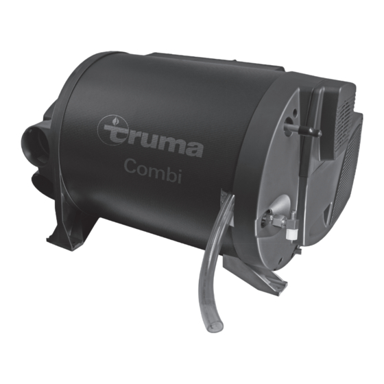
Truma Combi® 2 E / 4 E (Australia) 1 Control panel (digital) 2 Room temperature sensor 3 Cold water connection 4 Hot water connection 5 Gas connection (with pressure test point – not shown) 6 Hot air outlets 7 Recirculated air intake... -
Page 3: Symbols Used
– Any discharge pipe connected to the – The unit may be operated only with appropri- P&T relief valve is to be installed in a con- ate Truma control panels and accessories. tinuously downward direction and in a frost free ambient. - Page 4 – We recommend the gas pressure control accepted. system Truma MonoControl CS for vehicles and the Truma gas pressure control sys- – To prevent damage to the device from spray tem DuoControl CS for dual-cylinder gas water, such as when cleaning the vehicle, do systems.
-
Page 5: Function Description
– modifications to the exhaust duct and the water is required, select hot water mode. cowl, 3 different options are available for operating the unit: – failure to use original Truma parts as re- placement parts and accessories, – gas mode only LPG for autonomous use –... -
Page 6: Operating Instructions
Operating instructions can be viewed in offline mode appliance is still hot. with a mobile device and the Truma App. Download the – Do not place a plug or reducing coupling in the dis- operating instructions when you have a WiFi connection and charge pipe (Fig. -
Page 7: Draining The Hot Water System
If the heater is not going to be used for a long period of time, close the quick-acting valve in the gas supply line and turn off the gas cylinder. Maintenance Only original Truma parts may be used for maintenance and repair work! T 10 A Servicing should be carried out only by authorised personnel. -
Page 8: Overheating Protection 240 V
Faults Overheating protection 240 V Faults – Heater The 240 V heating facility has a mechanical overheating switch. If the 12 V power supply is interrupted during opera- Descriptions of possible fault causes and a troubleshoot- tion or during the after-run period, for example, the tempera- ing guide can be found in the operating instructions for the tures within the unit could activate the overheating protection. -
Page 9: Technical Data
Technical data Accessories Truma CP plus determined in accordance with EN 624 or Truma test conditions Digital control panel Truma CP plus with automatic air condi- Protection type / protection class tioning system for the iNet-capable Truma heaters Combi and... -
Page 10: Truma Warranty Policy
Warranty conditions – The company will only provide service on presentation of proof of purchase, on either the Truma product, or the Caravan / RV / Pleasure Craft in which the Truma product has been installed, to any authorised service agent. The pur- chaser must allow the service agent to photocopy the proof of purchase to facilitate his claim to the manufacturer. -
Page 11: Installation Instructions
In order to prevent damage to components inside the equip- – modifications to the exhaust duct and the cowl, ment, no cables or water lines of any kind may be attached to – failure to use original Truma parts as replacement parts and the equipment’s insulation. accessories, –... -
Page 12: Securing The Device
Exhaust gas removal cannot find its way into the vehicle interior. Only Truma exhaust duct AA 3 (part no. 39320-00) and The cowl must be in the form of a wall or roof cowl combustion air infeed ZR 80 (part no. 39580-00) may be used for the Combi 2 E / 4 E (Australia) heater because the unit was tested and approved only with these ducts. -
Page 13: Connecting The Exhaust Double Duct To The Device
The 4 connections on the unit are designed for the 65 mm diameter ÜR duct (part no. 40230-00). Only Truma ducts are approved with the heating system 11 12 and must be used. 3 – 4 Nm Use only pressure-safe ducts in compliance with Truma qual- Fig. -
Page 14: Gas Connection
For operating the water heater it is possible to use all pressure For optimum warm air distribution, Truma always recommends pumps and submergible pumps up to 280 kPa, also all mixing using the 4 warm air outlets of the heater. If only three warm taps with or without electrical switch. -
Page 15: Mounting Of The Discharge Pipe
A water pipe (hose) may only be fitted at a clearance of 1.5 m to the heater on the warm air duct. The Truma hose clip SC Drill hole with 18 mm di- can be used if this distance is observed. In the case of parallel ameter and pass through installations, e.g. -
Page 16: Installing The Room Temperature Sensor
a maximum overall length of 10 m using 2 x 0.5 mm² cable if necessary). The provided room temperature sensor must always be connected, otherwise the heater will switch to fault. Installing the control panel The installation of the control panel is described in the instruc- tions included with the control panel. -
Page 17: V Voltage Supply
15 V and the alternating current ripple is < 1.2 Vpp. We rec- Warnings ommend the automatic chargers from Truma for the different applications. Please ask your dealer. Other chargers may be used only with a 12 V battery as a buffer. - Page 20 In Australia, always notify the Dometic Service Centre if problems are encountered; in other countries the relevant service partners should be contacted (www.truma.com). Having the equipment model and the serial number ready (see type plate) will speed up processing. Dometic Pty Ltd...
Need help?
Do you have a question about the Combi 2 EAU and is the answer not in the manual?
Questions and answers