
Subscribe to Our Youtube Channel
Related Manuals for Fischer Panda 8000x


Summary of Contents for Fischer Panda 8000x
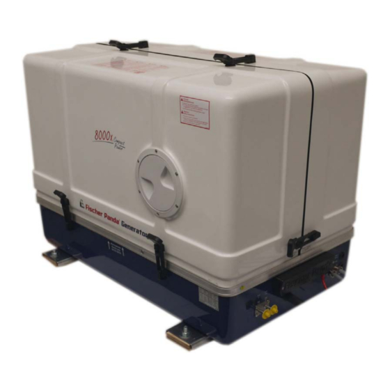
- Page 1 Vehicles Generator Manual Panda 8000x PVMV-N 8 kVA Panda 10000x PVMV-N 10k VA 230 V - 50 Hz 400 V - 50 Hz Super silent technology Panda_8000x-10000x_PVMV-N_eng.R01.1 10.6.16...
-
Page 2: Current Revision Status
Duplication and change of the manual is permitted only in consultation with the manufacturer! Fischer Panda GmbH, 33104 Paderborn, reserves all rights regarding text and graphics. Details are given to the best of our knowledge. No liability is accepted for correctness. Technical modifications for improving the product without previous notice may be undertaken without notice. -
Page 3: Table Of Contents
3.5.1 Bolted Fischer Panda transport box ................... 28 3.5.2 Fischer Panda transport box with metal tab closure ............28 Opening the MPL sound insulation capsule ..................29 3.6.1 Opening the GFK sound insulation capsule ............... 30 Transport and loading/unloading .................... - Page 4 Inhalt / Contens 3.8.1 Instructions for the starter battery for extended downtimes ..........31 3.8.2 Measures for short downtimes .................... 32 3.8.3 Measures for medium term downtimes / hibernation ............32 3.8.3.1 Courses for preservation: ..................32 3.8.3.2 Measures for removing surface protection after medium term downtimes (3 to 6 months).
- Page 5 Inhalt / Contens 5.9.3.3 Installation on the vehicle wall................59 5.9.3.4 Underfloor installation of radiator ................60 5.9.3.5 Installation location for radiator in the vehicle wall or cabin wall ......61 5.9.3.6 Installation location for radiator in a tunnel............62 5.9.3.7 Installation location for generators of the PVK-UK series ........
- Page 6 5.24 Electronic fan control for 3 phase fans PKD T5/PKD M10 Ziehl Abegg..........92 5.24.1 Configuration of the electronic fan control PKD T5 for Fischer Panda Generators .... 93 5.25 Configuration of the electronic fan control PKD M10 for Fischer Panda Generators......94 5.26 Insulation test ..........................
- Page 7 Inhalt / Contens 7.8.2 After the oil level check and refilling the oil ............... 108 Replacement of engine oil and engine oil filter ................. 109 7.9.1 After the oil change ......................111 7.10 Verifying the starter battery and (if necessary) the battery bank ............112 7.10.1 Battery ..........................
- Page 8 Inhalt / Contens 8.9.1.13 Generator must be shut off immediately if:............134 9 Appendix ..............................135 Engine oil ............................135 9.1.1 Engine oil classification ..................... 135 9.1.1.1 Operating range: ....................135 9.1.1.2 Quality of oil:..................... .. 135 Coolant specifications ........................
- Page 9 Inhalt / Contens 11.1.7.4 Set up the standby brightness of the CP-G............170 11.1.7.5 Set up the way of illustration of the overview screens of the CP-G ....170 11.1.7.6 Choose the language of the text screens of the CP-G........171 11.1.7.7 Set up temperature unit..................
- Page 10 Leere Seite / Intentionally blank Seite/Page 10 Kapitel/Chapter 2: 10.6.16...
- Page 11 Not only do you have a Fischer Panda generator on board, you also have worldwide support from the Fischer Panda Team. Please take the time to read this and find how we can support you further.
-
Page 12: General Instructions And Regulations
General Instructions and Regulations 1. General Instructions and Regulations 1.1 Safety first! These symbols are used throughout this manual and on labels on the machine itself to warn of the possibility of personal injury of lethal danger during certain maintenance work or operations. Read these instructions carefully. Can cause acute or chronic health impairments or death WARNING: Hazardous materials even in very small quantities if inhaled, swallowed, or... - Page 13 General Instructions and Regulations General warning of a hazard area WARNING: General warning Can cause acute or chronic health impairments or death WARNING: Danger due to inhalation and/or even in very small quantities if inhaled or ingested. ingestion Warning of live parts that may cause electric shock upon WARNING: Risk of electric shock upon contact contact.
-
Page 14: Tools
General Instructions and Regulations Wearing the applicable snugly fitting protective clothing MANDATORY INSTRUCTION: Wear snugly fitting provides protection from hazards and can prevent damage to protective clothing (PPE). your health. Wearing hearing protection provides protection from acute MANDATORY INSTRUCTION: Wear hearing and gradual hearing loss. - Page 15 General Instructions and Regulations Socket wrench set Hexagon socket wrench set Clamp-on ammeter (DC for synchronous generators; AC for asynchronous generators) Torque wrench 10.6.16 Kapitel/Chapter 1: General Instructions and Regulations - Seite/Page 15...
-
Page 16: Manufacturer Declaration In Accordance With The Machinery Directive 2006/42/Ec
• You will receive free upgrades as necessary. Additional advantages: Based on your complete data record, Fischer Panda technicians can provide you with fast assistance, since 90 % of the disturbances result from defects in the periphery. Problems due to installation errors can be recognized in advance. -
Page 17: Safety Instructions - Safety First
General Instructions and Regulations 1.5 Safety Instructions - Safety First! 1.5.1 Safe operation Careful handling of the equipment is the best insurance against an accident. Read the manual diligently, and make sure you understand it before starting up the equipment. All operators, regardless of their experience level, shall read this manual and additional pertinent manuals before commissioning the equipment or installing an attachment. -
Page 18: Safe Handling Of Fuels And Lubricants
General Instructions and Regulations 1.5.5 Safe handling of fuels and lubricants Keep fuels and lubricants away from naked fire. Before filling up the tank and/or applying lubricant, always shut down the generator and secure it against accidental start-up. Do not smoke and avoid naked flame and sparking near fuels and the generator. Fuel is highly flammable and may explode under certain conditions. -
Page 19: Safety Precautions Against Burns And Battery Explosions
General Instructions and Regulations 1.5.7 Safety precautions against burns and battery explosions The generator and its cooling agents and lubricants as well as the fuel can get hot while the generator is operated. Use caution around hot components such as parts containing exhaust fumes, radiator, hoses, and engine block during operation and after the generator was shut down. -
Page 20: Implementation Of Safety Inspections And Maintenance
General Instructions and Regulations 1.5.10 Implementation of safety inspections and maintenance Disconnect the battery from the engine before performing service work. Affix a sign to the control panel - both the main and the corresponding slave panel - with the instruction “DO NOT START UP - MAINTENANCE IN PROGRESS“... -
Page 21: Protective Conductor And Potential Equalisation
General Instructions and Regulations 1.6.1.1 Protective conductor and potential equalisation: Electric voltage above 60 V may be life-threatening. Fort this reason systems are grounded with a protective conductor. In connection with a RCD the current supply will be disconnected in case of a failure. Appropriate safety precautions like the RCD and corresponding fuses have to be provided by the customer to guarantee a save operation of the generator. -
Page 22: Safety Instructions Concerning Cables
• Battery connection cables shall be installed with utmost care and shall be checked for excessive heating under load. Check the battery near vibrating components regularly for chafing and insulation defects. ATTENTION! For battery charger generators (Fischer Panda AGT-DC)! Prior to installation, verify that the voltage of the battery bank complies with the output voltage of the generator. -
Page 23: In Case Of Emergency First Aid / Im Notfall - Erste Hilfe
In case of Emergency First Aid / Im Notfall - Erste Hilfe 2. In case of Emergency First Aid / Im Notfall - Erste Hilfe First Aid in case of accidents by electrical shocks 5 Safety steps to follow if someone is the victim of electrical shock Do not touch the injured person while the generator is running. -
Page 24: When An Adult Stops Breathing
In case of Emergency First Aid / Im Notfall - Erste Hilfe 2.7 WHEN AN ADULT STOPS BREATHING DO NOT attempt to perform the rescue breathing Warning: techniques provided on this page, unless certified. Performance of these techniques by uncertified personnel could result in further injury or death to the victim. -
Page 25: Basics
This manual contains the working instructions and operating guidelines for the owner and user of Fischer Panda generators. The manual is the base and the guideline for the correct installation and maintenance of Fischer Panda generators. It does not substitute the technical evaluation and should be used as an example guide only. The installation must be undertaken and proved by a suitable qualified/trained person and should be in accordance with the law as required by the country and special situation. -
Page 26: User
Basics 3.2.3 User Users are persons, established by the operator/owner, to operate the generator. The operator/owner has to ensure that the user has read and understood the manual and that all hazard notes and safety instructions are respected. The user must be instructed by the operator/owner regarding his activity at the generator, especially concerning the maintenance. - Page 27 Basics 3. AC-Control Box Fig. 3.3-3: AC-Control box representative picture Not present at all models 4. FP- Bus cable 15 mtr Fig. 3.3-4: FP- Bus cable 15 mtr 5. Termination resistor Fig. 3.3-5: Termination resistor 10.6.16 Kapitel/Chapter 3: Basics - Seite/Page 27...
-
Page 28: Range Of Operation
4. Remove the bolts for sidewalls / floor pallet 5. Remove the sidewalls 6. Open the generator attachment 3.5.2 Fischer Panda transport box with metal tab closure 1. Bend up the metal tab closures on the transport box lid 2. Remove the cover 3. -
Page 29: Opening The Mpl Sound Insulation Capsule
Basics 3.6 Opening the MPL sound insulation capsule To open the sound insulation capsule, the closures must Fig. 3.6-1: Sound insulation capsule, side part be rotated roughly 180° counter-clockwise. Use a flat head screwdriver. Pull the sidewalls out by gripping into the slots. -
Page 30: Opening The Gfk Sound Insulation Capsule
3.7.1 Transporting the generator • The generator must always be upright for transport. • For transport, the Fischer Panda transport box shall be used for the generator. The generator shall be securely attached to the bottom of the box. • For loading/unloading, an adequate industrial truck shall be used. -
Page 31: Special Service Instructions And Measures For Extended Machine Downtimes And Decommissioning
The decommissioning and storage must be undertaken and Note: proved regarding the operation and storage situation. Fischer Panda takes no responsibilty for damages through wrong decommissioning and storage. Downtimes are categorised in the following groups: • Short downtime (1 to 3 months) •... -
Page 32: Measures For Short Downtimes
- 25.2 V upper open-circuit voltage (full battery) - trickle charge full battery at 26.4 V. These values are based on a battery temperature of 20-25°C. Observe the instructions from the battery manufacturer. Fischer Panda recommends: Note: Starter battery recommendation • Install battery circuit breaker and switch to OFF on the machine. -
Page 33: Measures For Removing Surface Protection After Medium Term Downtimes
Basics • Spray engine parts and V-belt disks with preservative. • Clean air filter housing and spray with preservative (metal housing only). • Close off intake and exhaust apertures (e.g. with tape or end caps). Before recommissioning, remove preservatives and Attention! protective measures. -
Page 34: Measures For Removing Surface Protection After Extended Downtimes / Recommissioning (Over 6 Months)
• Hold stop lever on generator motor in neutral position and crank starter for approx. 10 seconds. Then, pause for 10 seconds. Repeat this procedure 2 times. • Perform visual check of the generator similar to initial commissioning and start up generator. Fischer Panda recommends: Note: After extended downtimes, a full 150 h inspection as per the inspection list should be performed. -
Page 35: The Panda Generator
The Panda Generator 4. The Panda Generator 4.1 Type plate at the Generator Fig. 4.1-1: Type plate Fig. 4.1-2: Discription type plate 10.6.16 Kapitel/Chapter 4: The Panda Generator - Seite/Page 35... -
Page 36: Description Of The Generator
The Panda Generator 4.2 Description of the Generator 4.2.1 Right Side View Fig. 4.2.1-1: Right Side View 01. Water-cooled exhaust elbow 10. Generator power terminal box 02. Compensator under heat isolation 11. Starter motor 03. Coolant pipe, exhaust elbow - silencer 12. -
Page 37: Left Side View
The Panda Generator 4.2.2 Left Side View Fig. 4.2.2-1: Left side View 01. Water-cooled silencer 08. Fuel solenoid valve 02. Ventilation screw silencer 09. Oil dipstick 03. Air suction housing with air filter 10. Fuel filter 04. Actuator for rpm-regulation 11. -
Page 38: Front View
The Panda Generator 4.2.3 Front View Fig. 4.2.3-1: Front view 12 13 01. Pulley for internal cooling water pump 10. xControl connection panel 02. Fuel solenoid valve 11. Cable AC-Control box 03. Oil dipstick 12. Cable Load 04. Cooling water intake pipe 13. -
Page 39: Back View
The Panda Generator 4.2.4 Back View Fig. 4.2.4-1: Back view 01. Water-cooled silencer 04. Air intake 02. Return-flow external expansion tank 05. Connection external expansion tank 03. Connection exhaust hose 10.6.16 Kapitel/Chapter 4: The Panda Generator - Seite/Page 39... -
Page 40: Details Of Functional Units
The Panda Generator 4.3 Details of functional units 4.3.1 xControl panel The control panel is fitted with various monitoring functions, which increase functional reliability and operating safety of the generator. Various parts of the generator are monitored with sensors which, when triggered, generate an error message and can shut down generator operation under certain circumstances to prevent damage. -
Page 41: The Cooling System
The Panda Generator 4.3.2 The cooling system Fig. 4.3.2-1: The cooling system 10.6.16 Kapitel/Chapter 4: The Panda Generator - Seite/Page 41... -
Page 42: The Fuel And Combustion Air System
The Panda Generator 4.3.3 The fuel and combustion air system Fig. 4.3.3-1: The fuel and combustion air system Seite/Page 42 - Kaptitel/Chapter 4: The Panda Generator 10.6.16... -
Page 43: Components Of Electrical System
The Panda Generator 4.3.4 Components of electrical system 4.3.5 Sensors and switches for operating surveillance Thermo-sensor at cylinder head Fig. 4.3.5-1: Thermo-switch cylinder head The thermo-sensor at the cylinder head serves the monitoring of the generator temperature. Thermo-sensor at water-cooled exhaust elbow Fig. - Page 44 The Panda Generator Oil pressure switch Fig. 4.3.5-4: Oil pressure switch In order to be able to monitore the lubricating oil system, an oil pressure switch is built into the system. The oil pressure switch is on the back of the engine (before the electrical starter).
-
Page 45: The Oil Circuit - Schema
The Panda Generator 4.3.6 The oil circuit - Schema Fig. 4.3.6-1: The oil circuit - Schema 10.6.16 Kapitel/Chapter 4: The Panda Generator - Seite/Page 45... - Page 46 The Panda Generator Leere Seite / Intentionally blank Seite/Page 46 Kapitel/Chapter 4: The Panda Generator 10.6.16...
-
Page 47: Installation Instructions
Damages caused by faulty or incorrect installation are not covered by the warranty. 5.1 Personal requirements The described installation must be done by a technical trained person or a Fischer Panda service point. 5.1.1 Hazard notes for the installation see “Safety first!” on Page 12. - Page 48 Installation Instructions Oil and fuel vapours can ignite on contact with ignition -Warning!: Danger of fire sources. Therefore: • No open flames during work on the generator. • Do not smoke. • Remove oil and fuel residues from the generator and floor. Contact with engine oil, antifreeze and fuel can result in Danger!: Danger of poisoning damage to health.Therefor:...
-
Page 49: Environmental Protection
Installation Instructions 5.2 Environmental protection Engine liquids/batteries are harmful for the environment. Environmental protection. Collect discharged engine liquids and dispose it properly. Batteries should be disposed properly. 10.6.16 Kapitel/Chapter 5: Installation Instructions - Seite/Page 49... -
Page 50: Placement
The convenient base consists of a stable framework, on which the generator is fastened by means of shockmounts. The combustion air can be sucked in unhindered. Fischer Panda recommend captive shock mount! Seite/Page 50 - Kaptitel/Chapter 5: Installation Instructions 10.6.16... - Page 51 Installation Instructions 01. Shock mount Fig. 5.3.3-1: Shock mount representative picture 02. Captive shock mount representative picture 10.6.16 Kapitel/Chapter 5: Installation Instructions - Seite/Page 51...
-
Page 52: Air Suction Filter As A Source Of Noise
If this is the case, an air intake muffler with the appropriate nominal width should be ordered from Fischer Panda. This is a cylinder, which takes up relatively large amount of room (Total length approx 700mm, Diameter 100mm). - Page 53 The external Fuel pump should be installed near the tank Electrical fuel pump Fig. 5.6.0-1: electrical fuel pump With the Fischer Panda generator is usually supplied an external, electrical fuel pump (DC). The fuel pump must be installed close at the fuel tank. The electrical connections is prepared at the generator.
-
Page 54: Connection Of The Fuel Lines At The Tank
Installation Instructions External fine filter Fig. 5.6-3: externer Feinfilter At generators with Kubota EA 300 or Farymann engines, the fine filter is delivered with the generator. This fine filter should be installed in the fuel feed line next to the generator. representative picture 5.6.1 Connection of the fuel lines at the tank General fuel feed and return line must be connected to the... -
Page 55: Ventilating The Fuel System
PVK-UK or the PSC series. Depending on the purpose and installation situation, a wide variety of Fischer Panda radiators are available for the optimum customization of the system. Operation with a commercially available vehicle radiator is possible. The cor- responding dimensioning must be implemented by the installer. -
Page 56: Determining The Size Of The Radiator
Installation Instructions 5.9.1 Determining the size of the radiator The size of the radiator must be dimensioned in accordance with the total thermal load, the operating conditions, and the installation situation. In principle, the thermal load of the generator equals 1.8 Note: times the electrical rated power (1.8 times with a water- cooled silencer, 1.2 times with a dry silencer) in kW. -
Page 57: Installation Location For Radiators For Roof, Side, Or Underfloor Mounting On The Vehicle
Installation Instructions 5.9.3.1 Installation location for radiators for roof, side, or underfloor mounting on the vehicle Fig. 5.9.3-1: Radiator installation - example 1. Radiator mounted on the roof 3. Radiator build into the vehicle wall 2. Radiator mounted in vertical position 4. - Page 58 Installation Instructions Fig. 5.9.3.2-1: Schematic: radiator, roof installation Fig. 5.9.3.2-2: Schematic: radiator, roof installation Seite/Page 58 - Kaptitel/Chapter 5: Installation Instructions 10.6.16...
-
Page 59: Installation On The Vehicle Wall
Installation Instructions 5.9.3.3 Installation on the vehicle wall Please note: • Minimum distance to vehicle wall: 100 mm. • Min. distance to gas exhaust (heat and dirt source): 500 mm. • The max. permissible vehicle length or width must not be exceeded. •... -
Page 60: Underfloor Installation Of Radiator
• Minimum distance to ground: 1/2 radiator width • Min. distance to gas exhaust (heat and dirt source): 500 mm. • The max. permissible vehicle height must not be exceeded. Fischer Panda does not recommend underfloor Note: installation. The radiator can quickly become dirty. Rock impacts can result in damage to the radiator. -
Page 61: Installation Location For Radiator In The Vehicle Wall Or Cabin Wall
Installation Instructions 5.9.3.5 Installation location for radiator in the vehicle wall or cabin wall A cabin installation is achieved if the set-up location is freely accessible during operation and serves as a working space, if applicable. Please note: • If persons are present in the set-up space during operation, a safety circuit must ensure that the air intake is opened. Incorrect installation in the cabin Fig. -
Page 62: Installation Location For Radiator In A Tunnel
Installation Instructions 5.9.3.6 Installation location for radiator in a tunnel A tunnel installation is implemented if the set-up location is separated from the vehicle cab by constructive measures. Please note: • The total of the air intakes must be at least equal to the radiator width ( •... -
Page 63: Installation Location For Generators Of The Pvk-Uk Series
Installation Instructions 5.9.3.7 Installation location for generators of the PVK-UK series Generators of the PVK-UK series are designed for lateral installation on the vehicle chassis Please note: • Min. distance between radiator and vehicle chassis must be 1/2 B. • Min. distance to gas exhaust (heat and dirt source): 500 mm. •... -
Page 64: Coolant Expansion Tank
T-fitting. The coolant expansion tank can be procured from the Fischer Panda accessories. Coolant expansion tank for systems with a radiator installed above the generator. -
Page 65: Radiator Fan
Installation Instructions The pressure in the coolant circuit must not exceed Warning: 0.7 bar! Required coolant volume flow: Fig. 5.9.9-1: Coolant volume flow Generator type Coolant volume flow Panda 4500 min. approx. 10 L/min Panda 8000 - 10000 approx. 16 to 22 L/min Panda 12000 - 15000 approx. -
Page 66: Custom Installations
5.10 Custom installations The effects on the warranty must be agreed on a case-by-case basis with Fischer Panda. 5.10.1 External heat exchangers External heat exchangers shall be installed as per the specifications of the respective manufacturers. -
Page 67: Installation Schematics
Installation Instructions 5.11 Installation schematics At generators with xControl, the ECU measures the Note: coolant temperature at the exhaust manifold. The external temp switch sensor in the hydraulic lines is not necessary at these generators. 5.11.1 Installation for vertical radiator installation Fig. -
Page 68: Installation For Mounting The Radiator Under The Vehicle
Installation Instructions 5.11.2 Installation for mounting the radiator under the vehicle Fig. 5.11.2-1: Underfloor radiator - schematic 01. Ventilation line 04. T-fitting 02. Coolant expansion tank 05. Radiator 03. T-fitting with connection for thermal switch 06. Fan for radiator Seite/Page 68 - Kaptitel/Chapter 5: Installation Instructions 10.6.16... -
Page 69: Installation Schematic For Roof Mounted Radiator With Expansion Tank
Installation Instructions 5.11.3 Installation schematic for roof mounted radiator with expansion tank Fig. 5.11.3-1: Roof-mounted radiator - schematic 1. Engine bleed line 4. T-fitting for bleed line 2. Radiator (horizontal) 5. T-fitting with connection for thermal switch 3. Coolant expansion tank (integrated) 5.11.4 Installation Radiator with Intercooler -Schematic sample vertical Radiator Fig. -
Page 70: Exhaust Installation
Installation Instructions 5.12 Exhaust installation 5.12.1 Exhaust connection for roof outlet Fig. 5.12.1-1: Exhaust installation - scheme 1. Exhaust outlet 5. External pre-silencer (option) 2. Generator 6. Exhaust pipe 3. Roof through fitting 7. External series silencer (option) 4. Vibration damper (option) 8. -
Page 71: Connection Of The Electrical Components
Installation Instructions 5.13 Connection of the Electrical Components Fig. 5.13-1: Electrical Connections 1. Generator 6. Switchboard 2. External fuel pump 7. Battery main switch 3. Remote control panel 8. Battery fuse 4. AC control box 9. Starter battery 5. Radiator with fan 10.6.16 Kapitel/Chapter 5: Installation Instructions - Seite/Page 71... -
Page 72: Generator Ac System Installation
Installation Instructions 5.14 Generator AC System Installation Before the electrical system is installed, READ the Warning!: Electrical Voltage SAFETY INSTRUCTIONS of this manual FIRST! Be sure that all electrical installations (including all safety systems) comply with all required regulations of the regional authorities. - Page 73 Installation Instructions Fig. 5.15-1: AC-Control box single phase - example 1. Terminal block for excitation 4. Capacitors 2. Solenoid for radiator fan 5. Fuse for radiator fan (single phase) 3. Boost solenoid 10.6.16 Kapitel/Chapter 5: Installation Instructions - Seite/Page 73...
- Page 74 Installation Instructions Fig. 5.15-2: AC-Control box three phase - example 1. Terminal block for excitation 4. 3-Phase Current / Voltage measurement module 2. Boost solenoid 5. Capacitors 3. Solenoid for radiator fan 6. Fuse for radiator fan (single phase) Seite/Page 74 - Kaptitel/Chapter 5: Installation Instructions 10.6.16...
-
Page 75: Installation With Looped-In Ac-Control Box
Installation Instructions 5.15.1 Installation with looped-in AC-Control box All electrical safety installations have to be made on board (RCD etc.). Fig. 5.15.1-1: Installation with looped-in AC Control box 1. Generator 4. Distribution panel 2. Battery 5. Remote control panel 3. AC-Control box 6. -
Page 76: Electronic Voltage Control Xcontrol
Installation Instructions 5.15.3 Electronic voltage control xControl The xControl controls the generator voltageand motor speed. An actuator/servo on the injection pump can increasethe engine speed compared to the idle speed. If the generator runs without load, the frequency should be approx. 48,5 - 49 Hz (50 Hz System) or 58,5 - 59 Hz (60 Hz System). -
Page 77: Connection Of The Starter Battery Block
Installation Instructions 5.16.1 Connection of the starter battery block IAn own separate starter battery must be installed for the generator. The positive cable (+) of the battery is attached directly at the solenoid switch of the starter motor. The negative cable (-) of the battery is attached underneath the starter motor at the engine mount. - Page 78 Installation Instructions Positive battery cable Fig. 5.16.1-1: Positive battery cable The positive (+) battery cable is connected directly to the solenoid switch of the starter. Negative battery cable Fig. 5.16.1-2: Negative battery cable The negative (-) battery cable is connected to the engine foot.
-
Page 79: Connection Of The Remote Control Panel - See Separate Control Panel Manual
Terminal FP CAN-Bus (external xControl components) 5.16.3.1 xControl ECU The xControl ECU is the main modul of the xControl. installation and modifikation are only allowed by Fischer Panda or authorized service points. 10.6.16 Kapitel/Chapter 5: Installation Instructions - Seite/Page 79... -
Page 80: Fp Can-Bus For Internal Use
5.17 Radiator fan control / electronic fan control To control the radiator fan, various controls/electronic controls can be chosen from the Fischer Panda delivery program. In the following the basic functions of the fan controls Note!: are described. -
Page 81: Standard Fan Control For 1-Phase And 3-Phase Generators
Installation Instructions 5.18 Standard fan control for 1-phase and 3-phase generators. In the standard kit, the generators will be equipped with a one step fan control. Fan control 230 V Fig. 5.18-1: Fan control 230 V representative picture 10.6.16 Kapitel/Chapter 5: Installation Instructions - Seite/Page 81... - Page 82 Installation Instructions Fig. 5.18-2: Fan control 230 V Seite/Page 82 - Kaptitel/Chapter 5: Installation Instructions 10.6.16...
-
Page 83: Electronic Fan Control For Dc Fans Re 0201
Installation Instructions 5.19 Electronic fan control for DC fans RE 0201 For DC Fans the fan control RE 0201 can be used. Fig. 5.19-1: 5.20 Brief description Temperature-dependent continuous speed controlling device for one or two DC-fans. 5.20.1 Function The speed regulation of the fan is made by pulse tracing modulation (PWM) of the operating voltage. Pulse/no pulse ratio becomes over an external temperature sensor (NTC resistance to attach at clamp 7 and 8) dependent on the coolant temperature. -
Page 84: Master - Slave - Operation
Installation Instructions Poti Start: Adjusting the starting temperature (fan start-up). The start temperature is with left stop 60 °C and with right stop 80 °C. Ex factory a starting temperature of 70°C is adjusted (potentiometer position: In the middle). Poti Window: Adjusting the temperature window: With the potentiometer „Window“... -
Page 85: Function Of The Clamps For The Master-Slave-Operation
Installation Instructions Fig. 5.20.2-1: 5.20.3 Function of the clamps for the Master-Slave-Operation Clamp 11+12: Control input for slave operation. Clamp 11 is the positive input. Clamp 12 is the negative input. The input is floating, so that via this input connected fan controllers of the same source can be supplied, without a ground loop develops. Clamp 13+14: Output for the master-slave-operation. -
Page 86: Technical Data
Installation Instructions 5.21 Technical Data Characteristics closed current (electronics off) 0,5 mA closed current (electronics on) 10 - 15 mA Benchmark figure of the temperature control: fan start-up 60 °C - 80 °C max. number of revolution 65 °C - 100 °C tolerance of the temperatures ±... - Page 87 Installation Instructions maximum load current (3 sec) 28 A nominal voltage fan 24 VDC *1) The maximum input and/or output peak voltage is measured over the appropriate clamps of the fan controller. It may be exceeded at no time. This applies independently of whether a voltage increased height was possibly caused by the fan controller or an external component.
-
Page 88: Electronic Fan Control For Single Phase Fans Pke-2.5V_Ziehl Abegg
The electronic fan control variety the fan rpm stepless. 5.22.1 Preset for the use with Fischer Panda generators The Ziehl Abegg fan control is preset for the use with Fischer Panda generators. For the preset following data and jumper settings are used. -
Page 89: Connection Of The Sensor (Ziehl Abegg Kty)
Installation Instructions 5.22.2 Connection of the sensor (Ziehl Abegg KTY) The sensor is connected to E/GND. A resistor 4,2kOhm must be connected parallel to the sensor. Fig. 5.22.2-1: Connection plan 10.6.16 Kapitel/Chapter 5: Installation Instructions - Seite/Page 89... -
Page 90: Electronic Fan Control For Single Phase Fans Pxet6Q_Ziehl Abegg
The electronic fan control variety the fan rpm stepless. 5.23.1 Preset for the use with Fischer Panda generators The Ziehl Abegg fan control is preset for the use with Fischer Panda generators. For the preset following data and jumper settings are used. -
Page 91: Connection Of The Sensor (Ziehl Abegg Kty)
Installation Instructions 5.23.2 Connection of the sensor (Ziehl Abegg KTY) The input TB and D1 are bridget. The sensor is connected to E1/GND. A resistor 4,2kOhm must be connected parallel to the sensor. Fig. 5.23.2-1: Connection plan 10.6.16 Kapitel/Chapter 5: Installation Instructions - Seite/Page 91... -
Page 92: Electronic Fan Control For 3 Phase Fans Pkd T5/Pkd M10 Ziehl Abegg
Installation Instructions 5.24 Electronic fan control for 3 phase fans PKD T5/PKD M10 Ziehl Abegg The electronic fan control variety the fan rpm stepless. Fan control PKD T5 Fig. 5.24.0-1: Fan control PKD T5 representative picture Leere Seite / Intentionally blank Seite/Page 92 Kapitel/Chapter 5: Installation Instructions 10.6.16... -
Page 93: Configuration Of The Electronic Fan Control Pkd T5 For Fischer Panda Generators
Installation Instructions 5.24.1 Configuration of the electronic fan control PKD T5 for Fischer Panda Generators Fig. 5.24.1-1: Configuration of the fan control PKD T5 for Fischer Panda Generators 10.6.16 Kapitel/Chapter 5: Installation Instructions - Seite/Page 93... -
Page 94: Configuration Of The Electronic Fan Control Pkd M10 For Fischer Panda Generators
Installation Instructions 5.25 Configuration of the electronic fan control PKD M10 for Fischer Panda Generators Fig. 5.25.0-1: Configuration of the fan control PKD M10 for Fischer Panda Generators Seite/Page 94 - Kaptitel/Chapter 5: Installation Instructions 10.6.16... -
Page 95: Insulation Test
Installation Instructions 5.26 Insulation test Once the electrical system installation is complete, a ATTENTION! ground insulation test must be performed as follows: 1.) Switch off all on-board electrical devices. 2.) Start the generator. 3.) Measure the AC-voltage with a voltmeter (adjust to Volt/AC) between: a) generator housing and AC-Control box b) generator housing and ground. - Page 96 Installation Instructions Seite/Page 96 - Kaptitel/Chapter 5: Installation Instructions 10.6.16...
-
Page 97: Generator Operation Instruction
Generator operation instruction 6. Generator operation instruction 6.1 Personal requirements Only instructed persons are allowed to run the generator. Instructed Persons has read the manual of the generator and all ancillary components and external equipment. He must be acquaint with the specific risks and safety instructions. -
Page 98: Pre-Heating The Diesel Motor
It is harmless for the generator to deliver full nominal power for 2-3 hours. The hole conception of the Fischer Panda generator make sure, that the full power operation at extreme condition will not increase the engine temperatures over. Please note that the emissions of the generator also increase at full power operation. -
Page 99: Protection Conductor
6.3.5 Operating control system on the Fischer Panda generator Fischer Panda generators are equipped with various sensors/temperatures switches. The combustion engine is further equipped with a oil pressure control switch, which switches the motor off, if the oil pressure sinks to a particu- lar level. -
Page 100: Instructions For Capacitors - Not Present At All Models
Generator operation instruction 6.6 Instructions for capacitors - not present at all models Danger to Life - High voltage CAUTION! Do not touch the capacitor contact terminals! The generator's electrical system requires two different groups of capacitors: A) The booster capacitors B) The operating capacitors Both types are mounted in the electrical cabinet. -
Page 101: Maintenance Instructions
7.1 Personal requirements All maintenance, if not special marked, can be done by the trained persons. Further maintenance must be done by technical personal or Fischer Panda service points. 7.2 Hazard notes for the maintenance and failure Follow the general safety instruction at the front of this Notice!: manual. - Page 102 Maintenance Instructions Contact with engine oil, antifreeze and fuel can result in Danger!: Danger of poisoning damage to health. Therefor: • Avoid skin contact with engine oil, fuel and antifreeze. • Remove oil and fuel splashes and antifreeze from the skin immediately.
-
Page 103: Environmental Protection
Maintenance Instructions 7.3 Environmental protection Danger to the environment due to mishandling! Environmental protection. Significant environmental damage can occur, particularly for incorrect disposal, if environmentally hazardous operating materials are mishandled. Therefore: • Always observe the instructions mentioned below. • Take immediate action if environmentally hazardous materials reach the environment. - Page 104 Maintenance Instructions Open de-aerating screw at the cooling water pump. Fig. 7.6-1: De-aerating screw representative picture Open de-aerating screw at the thermostat-housing Fig. 7.6-2: De-aerating screw representative picture Open de-aerating screw at the water-cooled silencer. Fig. 7.6-3: De-aerating screw representative picture Seite/Page 104 - Kaptitel/Chapter 7: Maintenance Instructions 10.6.16...
- Page 105 Maintenance Instructions Pour in coolant through the cooling water filler cap. The Fig. 7.6-4: Cooling water filler cap coolant flows in very slow. representative picture If it is to be recognized that the cooling water level does not sag any longer (with cold cooling water the cooling water level must cover the sheet metal in the exhaust elbow union), close the de-aerating screws and start the generator.
-
Page 106: Replacing The Air Filter
Maintenance Instructions 7.7 Replacing the air filter 1. Open the closure on the right-hand side of the air intake Fig. 7.7-1: Replace air filter housing 01. Closure 2. Open the closure on the left-hand side of the air intake Fig. 7.7-2: Replace air filter housing. -
Page 107: Checking Oil-Level
Maintenance Instructions 7.8 Checking oil-level You require: paper towels / cloth for the oil dipstick The generator must be placed at level. • with vehicular generators: Place the vehicle on a levelled surface. • with PSC generators: Place the generator on a levelled surface. •... -
Page 108: Refilling Oil
• if the oil-level is under the minimum mark by less than 50h, there might be a technical problem! In that case, we recommend going to a shop or a Fischer Panda service point. • if the oil is cloudy or even „creamy“, coolant might have mixed with the oil. See a garage or a Fischer Panda service point immediately. -
Page 109: Replacement Of Engine Oil And Engine Oil Filter
Maintenance Instructions 7.9 Replacement of engine oil and engine oil filter You require: - Engine oil. See attachment. - New oil filter (not with generators with EA300 engines) - Sealing for oil drain screw - Personal protective gear - Container to collect used oil (heat resistant and of sufficient size) - Open-ended wrench for oil drain screw - Paper towels and cloth... - Page 110 Maintenance Instructions 2. Loosen oil filling cap Fig. 7.9-1: Oil filling cap Unscrew the oil filling cap. This is necessary, because otherwise a vacuum will form and the oil can not completely drain off. Sample picture 3. Open oil drain screw. Fig.
-
Page 111: After The Oil Change
Maintenance Instructions Oil screen with generators with EA300 engines Fig. 7.9-4: Oil screen The oil screen should be cleaned every 500 operating hours: to do so follow the instructions in the engine manual. Use spanner size 17 mm. Sample picture 6. -
Page 112: Verifying The Starter Battery And (If Necessary) The Battery Bank
Maintenance Instructions 7.10 Verifying the starter battery and (if necessary) the battery bank Check the condition of the battery. Proceed here as prescribed by the battery manufacturer. If from the battery manufacturer not otherwise mentioned. 7.10.1 Battery 7.10.1.1 Check battery and cable connections •... -
Page 113: Check Electrolyte Density
Maintenance Instructions 7.10.1.3 Check electrolyte density • Measure the electrolyte density of individual cells with a Fig. 7.10.1.3-1: Battery commercial hydrometer. The hydrometer reading (see table on following page) indicates the battery’s state of charge. During measurement, the temperature of the electrolyte should preferably be 20 °C. - Page 114 Maintenance Instructions Leere Seite / Intentionally blank Seite/Page 114 Kapitel/Chapter 7: Maintenance Instructions 10.6.16...
-
Page 115: Generator Failure
Generator Failure 8. Generator Failure 8.1 Personal requirements The work described here, unless otherwise indicated, are performed by the operator. More Repair work may be performed only by specially trained personnel or by authorized repair shops (Fischer Panda service points). This is especially for working on the valve timing, fuel injection system and the engine repair. 8.2 Hazard notes for the troubleshooting Follow the general safety instruction at the front of this Notice!:... - Page 116 Generator Failure Contact with engine oil, antifreeze and fuel can result in Danger!: Danger of poisoning damage to health. Therefor: • Avoid skin contact with engine oil, fuel and antifreeze. • Remove oil and fuel splashes and antifreeze from the skin immediately.
-
Page 117: Tools And Measuring Instruments
Generator Failure 8.3 Tools and measuring instruments In order to be able to manage disturbances while driving, following tools and measuring instruments should belong to the equipment on board: • Multimeter for voltage (AC), frequency and resistance • Measuring instrument for inductance •... -
Page 118: Generator Voltage Fluctuations And Monitoring
Generator Failure 8.4.3 Generator Voltage Fluctuations and Monitoring Before working (installation) on the System read the Notice!: section Safety Instructions in this Manual. During periods of high electric loading, the voltage may drop to 190 V/50 Hz (or 95 V/60 Hz) or even lower. Such voltage drops can potentially cause damage to certain electrical devices such as electric motors, compressors and electronic equipment. -
Page 119: Checking The Capacitors
Generator Failure 1) Switch off generator Fig. 8.5.1-1: Capacitor 2) Disconnect starter battery 3) Open AC-Control box The capacitors are discharged, by short circuit the two contacts. In addition use the cone end of an isolated screwdriver. 8.5.2 Checking the Capacitors Before working (installation) on the System read the ATTENTION! section „Safety Instructions“... - Page 120 Generator Failure Checking Fig. 8.5.2-2: Capacitor Switch the multimeter to „Continuity: acoustic signal“ and touch both capacitor terminals with the meter end probes. Test each capacitor by touching the multimeter (set on „continuity“) end probes on the capacitor terminals: only a brief „beep“...
-
Page 121: Testing Generator Stator Windings
Generator Failure 8.6 Testing generator stator windings 8.6.1 Checking the generator voltage In order to test, whether the fixed winding produces enough voltage, proceed in such a way: 1. Guarantee that the connection to the electrical system is interrupted. 2. Remove all conductions in the power terminal box of the generator. 3. -
Page 122: Measuring The Inductive Resistance
If this is not possible, the stator can be rewound by a qualified trades person/technician. Winding diagrams can be obtained from Fischer Panda GmbH, Germany. This test, unfortunately, is carried out at very low voltage (9 V) when a normal multimeter is used. Therefore only positive short circuits will be displayed. - Page 123 Generator Failure Generator Power Terminal Box 230 V / 50 Hz Fig. 8.6.5-1: Generator output terminal box 230 V / 50 Hz In these terminal box there are the electrical connection points for the AC generator. Here is also the bridge for the protective grounding of the generator.
- Page 124 Generator Failure Fig. 8.6.5-4: Wiring diagram HP3 - 400 V / 50 Hz Seite/Page 124 - Kaptitel/Chapter 8: Generator Failure 10.6.16...
- Page 125 Generator Failure Generator Power Terminal Box 120 V / 60 Hz Fig. 8.6.5-5: Generator power terminal box 120 V / 60 Hz Z1.2 In these terminal box there are the electrical connection points for the AC generator. Here is also the bridge for the protective grounding of the generator.
- Page 126 Generator Failure Generator Power Terminal Box 240 V / 60 Hz (208 V / Fig. 8.6.5-7: Generator power terminal box 240 V / 60 Hz 60 Hz) In these terminal box there are the electrical connection points for the AC generator. Here is also the bridge for the protective grounding of the generator.
- Page 127 Generator Failure Generator Power Terminal Box DVS - 120 V + 240 V / Fig. 8.6.5-9: Generator power terminal box DVS 60 Hz In these terminal box there are the electrical connection points for the AC generator. Here is also the bridge for the protective grounding of the generator.
-
Page 128: Coil Resistance Measurements In Stator Windings
In this case to get a save reading, use a MEGA-meter with a high test voltage If you find any abnormality, when doing this test, please ask your Fischer Panda dealer. If the measured resistance values deviate from each other significantly, then there is probably a short within the coils. -
Page 129: Measuring The Coil Inductive Resistance
Generator Failure 8.7 Measuring the Coil Inductive Resistance Unfortunately a reliable assessment of the winding's performance cannot be attained through checking only coil resistances. However, the symmetry of the coil resistances is a good indicator of winding performance. If the coil resistances are symmetric, the next step is to measure the winding's inductive resistance using a special meter (capable of measuring milli-Henrys). -
Page 130: Stop Solenoid
Generator Failure Fig. 8.8.1-1: Generator termination box Initializing the magnetic field in the windings through external current from a 4,5 - 9 volt battery. (No car- battery!) 8.8.2 Stop solenoid There are two different variations: A. Energized to stop By pressing the „OFF“-button on the remote control panel the stop solenoid is supplied with voltage and operate, through this the injection nozzles resets to zero position and the generator stops. -
Page 131: Damage To Starter Motor
Generator Failure 8.8.3 Damage to starter motor The starter is fitted with a free wheel or axial rotating spring cog, which prevents the starter being driven externally by means of the motor. The free wheel will be heavily worn, if the starter still operates, thereby causing damage to the springs, roller bearings or cog teeth. -
Page 132: Troubleshooting Table
Generator Failure 8.9 Troubleshooting Table 8.9.1 Generator faults 8.9.1.1 Generator output to low. For 50 Hz versions: less than 200 V. For 60 Hz versions: less than 100 V. Cause Solution Generator is overloaded. Reduce the electrical load. (Switch off load) Motor is not reaching the rated rpm. -
Page 133: Starter Motor Is Turning The Engine, But Generator Fails To Start
Generator Failure 8.9.1.6 Starter motor is turning the engine, but generator fails to start. Cause Solution Fuel inlet solenoid valve not opening. Check wire connections and circuitry to solenoid valve. (ref. DC wiring diagram: Relay K2, Fuse) Fuel pump not working. Check fuel-filter and pump: clean if necessary. -
Page 134: Motor Runs In Off Position
Generator Failure 8.9.1.10 Motor runs in off position. Cause Solution Fuel inlet solenoid valve or throttle shut solenoid is not switching off. Check wire connections to solenoid. Check valve functions as in the „Inlet Fuel Solenoid Valve“ or in the truckle shut off solenoid sections. Replace if necessary. -
Page 135: Appendix
Appendix 9. Appendix 9.1 Engine oil 9.1.1 Engine oil classification 9.1.1.1 Operating range: The operating range of an engine oil is determined by SAE class. „SAE“ is for the union of American auto engineers (Society of Automotives Engineers). The SAE class of an engine oil only informs over the viscosity of the oil (larger number = more viscous, smaller number = more highly liquidly) e.g. -
Page 136: Coolant Specifications
Use a mixture of water and antifreeze. The antifreeze needs to be suitable for aluminium. The antifreeze concentration must be regularly checked in the interests of safety. Fischer Panda recommend to use the product: GLYSANTIN PROTECT PLUS/G 48 Engine coolant automotive industry Product description Product name GLYSANTIN ®... -
Page 137: Technical Data Coil
Appendix in cetane rating, adversely effects the engine. 9.4 Technical data coil Data for generators not mentioned on request. Notice!: Fig. 9.4-1: Resistor generator coil HP1 Fig. 9.4-2: Inductance generator coil HP1 L-N [Ohm] L-Z [Ohm] L-N [Ohm] L-Z [Ohm] Mains 120V / 60Hz Mains... -
Page 138: Diameter Of Conduits Vehicle Generators
Appendix L1-N [mH] L2-N [mH] L3-N [mH] L1'-N [mH] 1-2[mH] 3-4[mH] Panda 8000 approx. 3,7 approx. 3,7 approx. 3,7 approx. 2,3 Panda 9000 approx. 3,7 approx. 3,7 approx. 3,7 approx. 2,3 Panda 12000 approx. 3,5 approx. 3,5 approx. 3,5 approx. 2,3 Panda 14000 approx. - Page 139 Appendix Generatortyp Kühlwasser Abgas Kraftstoff Generator type Cooling water Exhaust Fuel Zulauf Rücklauf Feed Return Panda PVM-NE 6000 ND Panda PVM-NE 6000i/8000i Panda PVM-NE 8000 NE Panda PVM-NE 9000 ND Panda PVM-NE 12000 NE Panda PVM-NE 14000 NE Panda PVM-NE 15000 NE / 15000i Panda PVM-NE 18 NE Panda PVM-NE 24 NE Panda PVM-NE 30 NE...
- Page 140 Appendix Generatortyp Kühlwasser Abgas Kraftstoff Generator type Cooling water Exhaust Fuel Zulauf Rücklauf Feed Return Panda PVK-UK 5000 LPE Panda PVK-UK 6000 ND Panda PVK-UK 6000i/8000i Panda PVK-UK 8000 NE Panda PVK-UK 9000 ND Panda PVK-UK 12000 NE Panda PVK-UK 14000 NE Panda PVK-UK 15000 NE / 15000i Panda PVK-UK 9-4 Panda PVK-UK 18 NE...
-
Page 141: Rated Current
Appendix 9.6 Rated current Data for generators not mentioned on request. Notice!: Fig. 9.6-1: Rated current Generator Current Generator Current Panda 8000 - 230 V / 50 Hz 27,0 A Panda 18 - 230 V / 50 Hz 60,3 A Panda 8000 - 400 V / 50 Hz 8,3 A Panda 18 - 400 V / 50 Hz... - Page 142 Appendix Panda 4000s Panda 4200 FCB 4500FCB Panda 4k Panda 5000 LPE Panda 4,5ND Panda 5k Valve clearance (engine cold) 0,2 mm 0,2 mm 0,2 mm 0,2 mm 0,16 - 0,20 mm Cylinder head nut torque 30-33 Nm 30-33 Nm 30-33 Nm 42 Nm 58,8 - 63,7 Nm...
- Page 143 Appendix Panda 6500 Panda 8000 Panda 9000 Panda 10000 Panda 12000 Panda 7 mini Panda 8 mini Panda 9 mini Max. exhaust back pressure 9,3 kPa 9,3 kPa 9,3 kPa 9,3 kPa 9,3 kPa 93 Millibar 93 Millibar² 93 Millibar 93 Millibar 93 Millibar ²...
- Page 144 Appendix Panda 30 IC Panda 40 LN Panda 47 LN Panda 60 MB Panda 75 MB Idle running speed ² 2900 rpm 3000 rpm 3000 rpm 2900 rpm Valve clearance (engine cold) 0,2 mm Hydro Hydro 0,2 mm Cylinder head nut torque 63,7 - 68,6 Nm 68 Nm 68 Nm...
- Page 145 Appendix Panda 7,5-4 Panda 9-4 Panda 12-4 Panda 17-4 Panda 22-4 Max. exhaust back pressure 10,7 kPa 10,7 kPa 10,7 kPa 10,7 kPa 10,7 kPa 107 Millibar 107 Millibar 107 Millibar 107 Millibar 107 Millibar ² progressive speed by VCS ³...
- Page 146 Appendix Panda 5000i Panda 8000i Panda 10000i Panda 15000i Panda 25i Idle running speed 2900 rpm 2900 rpm 3100 rpm 2900 rpm 1800 rpm Valve clearance (engine cold) 0,16 - 0,20 mm 0,2 mm 0,2 mm 0,2 mm 0,2 mm Cylinder head nut torque 58,8 - 63,7 Nm 42 Nm...
- Page 147 Appendix ³ 0,35 l/kW electrical power, the randomized values between 30 % and 80 % of the rated speed 10.6.16 Kapitel/Chapter 9: Appendix - Seite/Page 147...
- Page 148 Appendix Leere Seite / Intentionally blank Seite/Page 148 Kapitel/Chapter 9: Appendix 10.6.16...
- Page 149 Panda xControl Manual Panda_xControl_eng.R01.5 10.6.16...
-
Page 150: Current Revision Status
Duplication and change of the manual is permitted only in consultation with the manufacturer! Fischer Panda GmbH, 33104 Paderborn, reserves all rights regarding text and graphics. Details are given to the best of our knowledge. No liability is accepted for correctness. Technical modifications for improving the product without previous notice may be undertaken without notice. -
Page 151: Safety Instructions Panda Xcontrol
10. Safety Instructions Panda xControl 10.1 Personal requirements The settings described here can by performed by the operator, unless otherwise indicated. The installation should be carried out by specially trained personnel or by authorized repair shops (Fischer Panda service points). 10.2 Safety instructions... - Page 152 Safety Instructions Panda xControl Note also the safety of the other components of your Note! system. Seite/Page 152 - Kaptitel/Chapter 10: Safety Instructions Panda xControl 10.6.16...
-
Page 153: Panda Xcontrol
The module contains the entire control electronics. The xControl GC-S is normally mounted inside of the generator capsule. The xControl GC-S takes over the control and monitoring of the diesel engine of a Fischer Panda generator as well 10.6.16 Kapitel/Chapter 11: Panda xControl - Seite/Page 153... -
Page 154: Xcontrol - Cb-G
11.0.6 Installation of the xControl - CP-G The xContol - CP-G is a CAN Bus module. All Fischer Panda Can Bus modules has two RJ45 sockets. One is to connect the module to the CAN Bus. In the second another Modul can be plugged in to continue the CAN Bus. The Seite/Page 154 - Kaptitel/Chapter 11: Panda xControl 10.6.16... -
Page 155: 2Operation
Panda xControl last module in the row must have a termination resistor plugged into the second RJ45 socket. It is mandatory to use the Fischer Panda bus cable to connect the modules. Fig. 11.0-1: xControl CP-G Reverse Side RJ45 Fig. 11.0-2: Connection Schema Operation The xControl will be controlled with the xControl CP-G panel. -
Page 156: Switching On The Generator
Panda xControl 11.0.7 Switching on the generator Press the „ON/OFF“ Button to switch the generator on Fig. 11.0.7-1: Switch the generator on With this you switch the generator into the standby mode. If the automatic start option is set in the menu, the generator may start by an external signal. -
Page 157: Overview Screen With Activated Autostart
Panda xControl Fig. 11.0.7-5: Overview screen 1 english text Fig. 11.0.7-6: Overview screen 1 german text 11.0.7.1 Overview screen with activated autostart Danger for life! - The generator can be equipped with a Warning! Automatic start automatic start device. This means the generator can be started by an external signal. - Page 158 Panda xControl Overview screen 1 english text with autostart enabled Fig. 11.0.7-2: Overview screen 1 english text with autostart Overview screen 1 german text with autostart enabled Fig. 11.0.7-3: Overview screen 1 german text with autostart If the generator is running in the autostart mode and stopped manually, the autostart will fall back to „off“. Seite/Page 158 - Kaptitel/Chapter 11: Panda xControl 10.6.16...
-
Page 159: The Overview Screens
Panda xControl 11.0.8 The Overview Screens Which overview screen the display shows (symbolic-english text-german text) can be set up in the menu. 11.0.9 Overview Screens Symbolic Which screen the display shows (symbolic or english text or Fig. 11.0.9-1: Overview screen 1 symbolic german text) can be set up in the menu. -
Page 160: Overview Screens English Text
Panda xControl The fourth screen shows Fig. 11.0.9-4: Overview screen 4 symbolic 11. Temperature of the cylinder head 12. Temperature of the generator coil 13. Temperature of the exhaust The fifth screen is the „Enter the menu“ screen. Fig. 11.0.9-5: Overview screen 5 symbolic Press the Start/Stop - Enter button to enter the menu 11.0.10 Overview Screens English Text Which screen the display shows (symbolic or english text or... -
Page 161: Overview Screens German Text
Panda xControl The third screen shows Fig. 11.0.10-3: Overview screen 3 english text 10. Temperature of the cylinder head 11. Temperature of the generator coil 12. Temperature of the exhaust 13. Voltage of the starter battery The fourth screen is the „Enter the menu“ screen. Fig. - Page 162 Panda xControl The third screen shows Fig. 11.0.11-3: Overview screen 3 german text 10. Temperature of the cylinder head 11. Temperature of the generator coil 12. Temperature of the exhaust 13. Voltage of the starter battery The fourth screen is the „Enter the menu“ screen. Fig.
-
Page 163: Start Of The Generator
Panda xControl 11.1 Start of the Generator 11.1.1 Marine version starting preparation / Checks (daily) 1. Oil level control (ideal level: 2/3 MAX). The level should be about 2/3 of the maximum level of a cold engine. Further, if installed, the oil level of the oil-cooled bearing must be controlled before each start - see sediment bowl at generator front cover!. -
Page 164: Starting The Generator
Panda xControl 11.1.3 Starting the generator Danger for life! - The generator can be equipped with a Warning! Automatic start automatic start device. This means the generator can be started by an external signal. To avoid an unexpected starting of the generator, the starter battery must be disconnected before start working at the generator. -
Page 165: Stopping The Generator
Panda xControl The first seconds the engine run on idle speed. After that the Fig. 11.1.3-5: Raise speed xControl raises the speed to nominal and shows it in the display. As soon as the AC ok is shown, the load can be switched on Fig. -
Page 166: The Menu
Panda xControl 3. To stop the generator, press the Start Stop - Enter button. Fig. 11.1.4-1: Stop Never switch off the battery until the generator has Attention! stopped, if necessary close fuel valve! The Menu The Last screen of the overview is the „Enter the menu Fig. -
Page 167: Main Menu
„Generator“ you can change the generator relevant settings. For example Switch on the fuel pump for deaerating etc. 3. Service the submenu „Service“ is a restricted area for Fischer Panda Staff. 4. Back 10.6.16 Kapitel/Chapter 11: Panda xControl - Seite/Page 167... -
Page 168: Submenu „Panel
Panda xControl 11.1.6 Submenu „Panel“ Fig. 11.1.6-1: Submenu „Panel“ 11.1.7 Submenu „Generator“ In the submenu „Panel“ following points can be set up Fig. 11.1.7-1: Submenu „Panel“ 1. Brightness of the panel 2. Contrast of the panel 3. Standby time out of the Panel 4. -
Page 169: Set Up The Contrast Of The Cp-G
Panda xControl Increase /decrease with the „Step-up“/“Step-down“ buttons Fig. 11.1.7.1-1: Submenu „brightness“ the value and confirm with the „Start/Stop - Enter“ button. Choose cancel or confirm with the „Step-up“/“Step-down“ buttons and confirm with the „Start/Stop - Enter“ button. 11.1.7.2 Set up the contrast of the CP-G Scroll with the „Step-up“/“Step-down“... -
Page 170: Set Up The Standby Brightness Of The Cp-G
Panda xControl Increase /decrease with the „Step-up“/“Step-down“ buttons Fig. 11.1.7.3-1: Submenu „standby timeoutl“ the value and confirm with the „Start/Stop - Enter“ button. Choose cancel or confirm with the „Step-up“/“Step-down“ buttons and confirm with the „Start/Stop - Enter“ button. 11.1.7.4 Set up the standby brightness of the CP-G Scroll with the „Step-up“/“Step-down“... -
Page 171: Choose The Language Of The Text Screens Of The Cp-G
Panda xControl Choose „symbolic view“ or text view“ with the „Step-up“/ Fig. 11.1.7.5-1: Submenu „way of illustration“ “Step-down“ buttons and confirm with the „Start/Stop - Enter“ button. Choose cancel or confirm with the „Step-up“/“Step-down“ buttons and confirm with the „Start/Stop - Enter“ button. If you choose „back“... -
Page 172: Reset All Values Of The Panel Submenu To Standard
Panda xControl Choose „degrees celsius“ or degrees fahrenheit“ with the Fig. 11.1.7.7-1: Submenu „temperature unit“ „Step-up“/“Step-down“ buttons and confirm with the „Start/ Stop - Enter“ button. Choose cancel or confirm with the „Step-up“/“Step-down“ buttons and confirm with the „Start/Stop - Enter“ button. If you choose „back“... -
Page 173: Submenu „Generator
Panda xControl 11.1.8 Submenu „Generator“ In the submenu „Generator“ following points can be set Fig. 11.1.8-1: Submenu „Generator“ 1. Autostart enable 2. Optional DC output 3. Switch outputs 4. Event log 5. Reset the generator submenu to standard 6. back to the main menu 11.1.8.1 Set up the autostart of the CP-G Scroll with the „Step-up“/“Step-down“... - Page 174 Panda xControl If any failure occur while the generator is starting or running, the generator will stop and the „Automatic Start“ will fall back to „off“. The first overview screen will show you, if the autostart is enabled Overview screen 1 symbolic with autostart enabled Fig.
-
Page 175: Set Up The Optional Dc Output Of The Cp-G
Panda xControl 11.1.8.2 Set up the optional DC output of the CP-G Scroll with the „Step-up“/“Step-down“ buttons to the menu point „optional DC output“ and confirm with the „Start/Stop - Enter“ button. You enter the menu point optional DC output. Choose „operation mode“... -
Page 176: Set Up The Operation Mode For The Opt. Dc-Power (Dp) Output Of The Cp-G
Panda xControl 11.1.8.3 Set up the operation mode for the opt. DC-Power (DP) output of the CP-G Fig. 11.1.8.3-1: Submenu „operation model“ 11.1.8.4 Set up the follow-up time for the opt. DP output of the CP-G Increase /decrease with the „Step-up“/“Step-down“ buttons Fig. -
Page 177: Check The Event Log Of The Cp-G
Panda xControl Choose „f.-pump“ or „opt. DC“ with the „Step-up“/“Step-down“ Fig. 11.1.8.5-1: Submenu „switch outputs“ and change the value from 0 to 1 or back with the „Start/Stop - Enter“ button. If you set the value to „1“ the output will be switched on, if you set the value to „0“... -
Page 178: Back To The Main Menu
Panda xControl Choose cancel or confirm with the „Step-up“/“Step-down“ Fig. 11.1.8.7-1: Submenu „reset to standard“ buttons and confirm with the „Start/Stop - Enter“ button. 11.1.8.8 Back to the main menu Scroll with the „Step-up“/“Step-down“ buttons to the menu point „back“ and confirm with the „Start/Stop - Enter“ button. -
Page 179: Failure
Panda xControl 11.2 Failure 11.2.1 Symbols and Messages in the Display 11.2.1.1 Message sample „Sensor defect“ A soon as a defect sensor is detected, the xControl Fig. 11.2.1.1-1: Sensor defect symbolic shows it in the display Fig. 11.2.1.1-2: Sensor defect english Fig. -
Page 180: Failure Code
Panda xControl Fig. 11.2.1.2-2: Sensor broken english Fig. 11.2.1.2-3: Sensor broken german 11.2.1.3 Failure code A Failure code is shown if any parameter run out of the Fig. 11.2.1.3-1: Failure code specified range. see “Failuretable” on page 180 11.2.2 Failuretable See chapter „Failure“... - Page 181 Panda xControl No.. Description Cause Explication Warning Gen.Stop Info Current sensor No voltage on supply current short circuit sensor defect Battery voltage battery voltage to low RPM failure RPM out of range Failure fuel supply n.a. Fuel empty Power out relay Failure power out relay Short circuit n.a.
- Page 182 Panda xControl No.. Description Cause Explication Warning Gen.Stop Info Reserved n.a. n.a. Seite/Page 182 - Kaptitel/Chapter 11: Panda xControl 10.6.16...
-
Page 183: Description Of Symbols
Panda xControl 11.2.3 Description of Symbols Fig. 11.2-1: Symbols Warning Failure shut down Failure Sensor Failure/Line open Broken Sensor Broken/short circuit AC Voltage Current Generator out Standby Automatic start Starter battery 10.6.16 Kapitel/Chapter 11: Panda xControl - Seite/Page 183... - Page 184 Panda xControl Power Generator out Load (%) Generator running Generator off Temperature Engine Exhaust Winding&Coil Preglow Example: Failure+Engine+Temperature Seite/Page 184 - Kaptitel/Chapter 11: Panda xControl 10.6.16...
-
Page 185: 1Zubehör
Panda xControl Zubehör: FP-Bus Kabel (15 m): 34.02.02.131H Fig. 11.2-2: FP-Bus Kabel (15 m): 34.02.02.131H Abschlußwiederstand:34.02.02.133H Fig. 11.2-3: Abschlußwiederstand:34.02.02.133H Adapter Rahmen: 31.03.20.263H Fig. 11.2-4: Adapter Rhamen: 31.03.20.263H xContol CP-G in einem Generator Control (P6+) Ausschnitt 10.6.16 Kapitel/Chapter 11: Panda xControl - Seite/Page 185... -
Page 186: Dimensionszeichnung
Panda xControl 11.2.3.1 Dimensionszeichnung Fig. 11.2.3.1-1: CP-G Seite/Page 186 - Kaptitel/Chapter 11: Panda xControl 10.6.16... - Page 187 Panda xControl Fig. 11.2.3-2: GC-S 10.6.16 Kapitel/Chapter 11: Panda xControl - Seite/Page 187...
- Page 188 Panda xControl Fig. 11.2.3-3: CB-G Seite/Page 188 - Kaptitel/Chapter 11: Panda xControl 10.6.16...
- Page 189 Panda xControl 10.6.16 Kapitel/Chapter 11: Panda xControl - Seite/Page 189...
- Page 190 Panda xControl Leere Seite / Intentionally blank Seite/Page 190 Kapitel/Chapter 11: Panda xControl 10.6.16...
Need help?
Do you have a question about the 8000x and is the answer not in the manual?
Questions and answers