Sign In
Upload
Manuals
Brands
Fischer Panda Manuals
Inverter
Panda AGT-DC 5000 PMS
Fischer Panda Panda AGT-DC 5000 PMS Manuals
Manuals and User Guides for Fischer Panda Panda AGT-DC 5000 PMS. We have
1
Fischer Panda Panda AGT-DC 5000 PMS manual available for free PDF download: Operation Manual
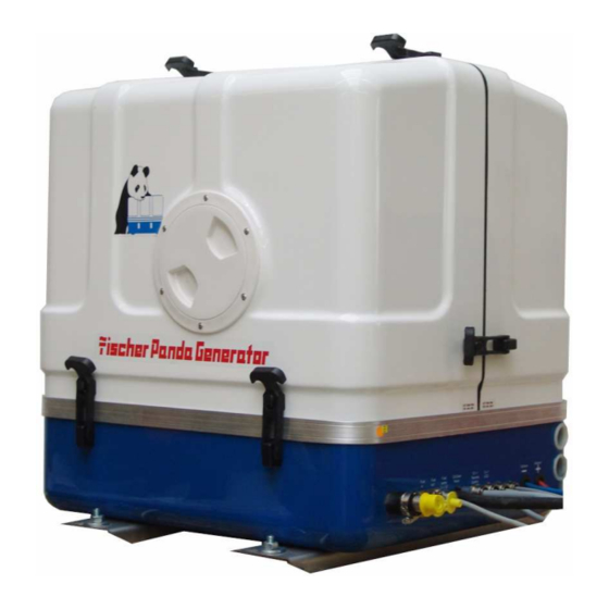
Fischer Panda Panda AGT-DC 5000 PMS Operation Manual (152 pages)
Marine Generator Super silent technology 12V - 250A / 4,5kW
Brand:
Fischer Panda
| Category:
Inverter
| Size: 8 MB
Table of Contents
Current Revision Status
2
Table of Contents
3
1 General References and Regulations
7
Safety First Symbols
8
Tools
13
Manufacturer Declaration in Accordance with the Machine Guideline 98/37/EG
15
Customer Registration and Guarantee
15
Technical Support
15
Attention, Important Directions Regarding Operation
15
Safety Instructions - Safety First
16
Safe Operation
16
Observe Safety Instructions
16
Wear Personal Protective Equipment (PPE)
16
Cleanness Protect
16
Safe Handling of Fuel and Lubricants - Keep Away from Fire
17
Exhaust Gases and Fire Prevention
17
Cautions against Burns and Battery Explosion
18
Keep Hands Away from Rotating Parts
18
Anti-Freeze and Disposal of Fluids
18
Implementation of Security and Maintenance
19
Warning and Caution Labels
19
Safety Instructions Concerning Operating the Generator
19
Protective Grounding and Potential Equalisation
20
Ground Wire
20
Switch off All Load When Working on the Generator
20
Safety Instructions Concerning the Cables
21
Recommended Starter Battery Size
21
Important Advice for Batteries - Starting Batteries and Traction Batteries
21
Safety Instructions for the Handling with Batteries
22
2 Special Notes and Safety Instructions for AGT- Generators
25
General Safety References Concerning Operation of an AGT Generator
25
Cooling of the Rectifier Block at the Marine Versions
25
Sample System AGT DC Generator
25
Measures to the Fire Protection
27
Special Tools
27
3 In Case of Emergency First Aid / IM Notfall - Erste Hilfe
29
When an Adult Stops Breathing
30
4 The Panda Generator
31
Type Plate at the Generator
31
Description of the Generator
32
Right Side View
32
Left Side View
33
Front View
34
Back View
35
Details of Functional Units
36
Components of Cooling System (Raw Water)
36
Components of Cooling System (Freshwater)
38
Components of the Fuel System
42
Components of Combustion Air
44
Components of the Electrical System
47
Sensors and Switches for Operating Surveillance
52
Components of the Oil Circuit
55
External Components
56
Operation Instructions
57
Daily Routine Checks before Starting
57
Starting Generator - See Remote Control Datasheet
58
Stopping the Generator - See Remote Control Datasheet
58
Starting the Generator by a „Failure Bypass Switch
58
5 Installation Instructions
59
Placement
59
Placement and Basemount
59
Notice for Optimal Sound Insulation
59
Generator Connections - Scheme
60
Cooling System Installation - Raw Water
61
General References
61
Installation of the Thru-Vessel Fitting in Yachts
61
Quality of the Raw Water Sucking in Line
61
Installation above Waterline
62
Installation below Waterline
63
The Freshwater - Coolant Circuit
65
Position of the External Cooling Water Expansion Tank
65
Ventilation at the First Filling of the Internal Cooling Water Circuit
66
Pressure Test for Control of Cooling Water Circuit
67
Watercooled Exhaust System
68
Installation of the Standard Exhaust System
68
Exhaust / Water Separator
69
Installation Exhaust/Water Separator
70
Fuel System Installation
72
General References
72
The Electrical Fuel Pump
73
Connection of the Fuel Lines at the Tank
73
Position of the Pre-Filter with Water Separator
74
Generator 12V DC System-Installation
74
Connection of the 12V Starter Battery
74
The Speed Sensor
76
Installation Panda AGT12V-System
77
Voltage Control System
79
Checking the VCS Voltage Control Without Requiring the Generator to Run
80
Funktion of the VCS
81
Checking the Voltage Regulation
81
Checking the Current Limit
82
Battery Monitor
83
6 Maintenance Instructions
85
General Maintenance Instructions
85
Checks before Starting
85
Hose Elements and Rubber Formed Component in the Sound Cover
85
Oil Circuit Maintenance
85
Execution of an Oil Change
86
Ventilating the Fuel System
88
Replace of the Fuel Filter
89
Checking the Water Separator in the Fuel Supply
90
Replace the Air Filter
90
Ventilating of the Coolant Circuit / Freshwater
91
Draining the Coolant
92
Replace of the V-Belt for the Internal Cooling Water Pump
93
The Raw Water Circuit
95
Clean Raw Water Filter
95
Causes with Frequent Impeller Waste
95
Replace the Impeller
96
Additional Maintenance
98
Conservation at Longer Operation Interruption
100
Measures on Preparation of the Winter Storage
100
Initiation at Spring
101
Replacing Water Pump
102
Replacing Valve Cover Gasket
103
Adjustment of the Valve Clearance
104
7 Generator Failure
107
Overloading the Generator
107
Starting Problems
107
VCS Does Not Work
107
Fuel Solenoid Valve and Stop Solenoid
109
Dirty Fuel Filter
110
Fuse on Control Panel Board
111
Failure Bypass Switch
111
Troubleshooting Table
112
8 Tables
113
Troubleshooting
113
Technical Data Engine
117
Types of Coil
119
Inspection Checklist for Services
120
Engine Oil
121
Coolant Specifications
122
Measurements
123
Generator Control Panel P6
125
Current Revision Status P6+ Manual
126
10 Safety Instructions Generator Control P6
127
Personal Requirements
127
Safety Instructions for this Chapter
127
11 General Operation
129
Panel Generator Control
129
Rear View 12V-Version
130
Rear View 24V-Version
131
Installation of the Remote Control Panel
132
Placement
132
Terminal Connections
132
Function of the Jumpers
133
Configuration and Adjustment
135
Configuration and Setting Sheet KE01
135
Configuration and Setting Sheet KE02
136
Configuration and Setting Sheet KE03
137
Configuration and Setting Sheet KE04
138
Starting Preparation / Checks (Daily)
139
Marine Version
139
Vehicle Version
139
Starting and Stopping the Generators
140
Starting the Generator
140
Stopping the Generator
141
Automatic Adapter - Optional
142
Function
142
The Mechanism Entrance
142
Terminal Connections
144
Master-Slave Adapter - Optional
145
Fischer Panda Art. No. 21.02.02.015H 12V-Version
145
Fischer Panda Art. No. 21.02.02.01H 24V-Version
145
Terminal Connections
146
Fuse
146
Terminal X2 ( IN/OUT from View Master-Opearating-Panel)
146
Terminal X3
147
Configuration and Adjustment
148
Configuration and Setting Sheet KE05
148
Configuration and Setting Sheet KE06
149
12 Measurements
151
Hole Pattern
151
Advertisement
Advertisement
Related Products
Fischer Panda Panda 5K PMS
Fischer Panda Panda AGT DC 5000
Fischer Panda Panda AGT/DC 10000 PMS
Fischer Panda Panda 5000i PMS
Fischer Panda 5000i PVK-U
Fischer Panda 5000i.Neo PMS
Fischer Panda 55-4 PSC
Fischer Panda Panda AGT-DC 4000 PMS
Fischer Panda Panda AGT-DC 6000 PVMV-N
Fischer Panda 0014668
Fischer Panda Categories
Portable Generator
Inverter
Controller
Control Panel
Control Systems
More Fischer Panda Manuals
Login
Sign In
OR
Sign in with Facebook
Sign in with Google
Upload manual
Upload from disk
Upload from URL