
Related Manuals for Omega DP6000


Summary of Contents for Omega DP6000
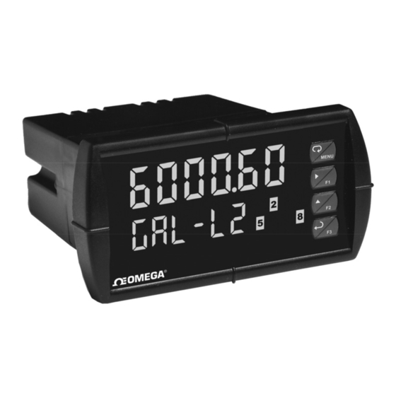
- Page 1 DP6000 Dual-Line Process Meter This datasheet has been downloaded from http://www.digchip.com at this page...
- Page 2 DP6000 Process Meter Instruction Manual...
- Page 3 In no event shall OMEGA be liable for consequential, incidental or special damages. CONDITIONS: Equipment sold by OMEGA is not intended to be used, nor shall it be used: (1) as a “Basic Component” under 10 CFR 21 (NRC), used in or with any nuclear installation or activity; or (2) in medical applications or used on humans.
- Page 4 Anyone using this product for such applications Warning! does so at his/her own risk. OMEGA shall not be held liable for damages resulting from such improper use.
-
Page 5: Table Of Contents
DP6000 Process Meter Instruction Manual Table of Contents INTRODUCTION ------------------------------------------------------------ 8 ORDERING INFORMATION --------------------------------------------- 9 SPECIFICATIONS --------------------------------------------------------- 10 General ----------------------------------------------------------------------------- 10 Process Input -------------------------------------------------------------------- 11 Relays ------------------------------------------------------------------------------ 12 Isolated 4-20 mA Transmitter Output ------------------------------------ 13 ®... - Page 6 Program Menu for Single Scale Process --------------------------- 40 Program Menu for Dual-Scale Level Applications ---------------- 40 Multi-Point Calibration & Scaling -------------------------------------- 41 DP6000-SOFT Software ------------------------------------------------ 41 Scaling the Meter (SCALE) ---------------------------------------------- 41 Dual-Scale for Level Application -------------------------------------- 42 ...
- Page 7 DP6000 Process Meter Instruction Manual Setting Up the Password (pass) ------------------------------------------- 68 Protecting or Locking the Meter ------------------------------------------- 68 Making Changes to a Password Protected Meter -------------------- 69 Disabling Password Protection -------------------------------------------- 69 Advanced Features Menu ---------------------------------------------------- 70 Advanced Features Menu &...
-
Page 8: Introduction
Figure 21. Acknowledge Relays w/Function Key or Digital Input .. 61 INTRODUCTION The DP6000 is a multi-purpose, easy to use digital process meter ideal for level, flow rate, temperature, or pressure transmitter applications. It accepts current and voltage signals (e.g. 4-20 mA, 0-10 V). Three of the front panel buttons can be custom- programmed for a specific operation. -
Page 9: Ordering Information
DP6000 Process Meter Instruction Manual ORDERING INFORMATION Standard Display Models 85-265 VAC 12/24 VDC Options Installed Model Model DP6000-6R0 DP6000-7R0 No options DP6000-6R2 DP6000-7R2 2 relays DP6000-6R3 DP6000-7R3 4-20 mA output DP6000-6R4 4 relays DP6000-6R5 2 relays & 4-20 mA output DP6000-6R7 4 relays &... -
Page 10: Specifications
PV1, PV2, PCT, d r-u, d gross, d nt-g, max/min, max & ASSIGNMENT min, set points, units (small display only), or Modbus input. PROGRAMMING Four front panel buttons, digital inputs, PC and DP6000-SOFT METHODS software, Modbus registers, or cloning using Copy function. NOISE FILTER... -
Page 11: Process Input
DP6000 Process Meter Instruction Manual NORMAL MODE Greater than 60 dB at 50/60 Hz REJECTION ISOLATION 4 kV input/output-to-power line 500 V input-to-output or output-to-P+ supply OVERVOLTAGE Installation Overvoltage Category II: CATEGORY Local level with smaller transient overvoltages than Installation Overvoltage Category III. -
Page 12: Relays
DP6000 Process Meter Instruction Manual LOW-FLOW 0-999999 (0 disables cutoff function) CUTOFF DECIMAL POINT Up to five decimal places or none: d. d dddd, d. d ddd, d. d dd, d. d d, d. d , dddddd CALIBRATION Input Minimum Span... -
Page 13: Isolated 4-20 Ma Transmitter Output
DP6000 Process Meter Instruction Manual Automatic reset only (non-latching), when the input passes the reset point. Automatic + manual reset at any time (non-latching) Manual reset only, at any time (latching) Manual reset only after alarm condition has cleared (latching) Note: Front panel button or digital input may be assigned to acknowledge relays programmed for manual reset. -
Page 14: Modbus ® Rtu Serial Communications
8 bit (1 start bit, 1 or 2 stop bits) PARITY Even, Odd, or None with 1 or 2 stop bits BYTE-TO-BYTE 0.01 – 2.54 second TIMEOUT TURN AROUND Less than 2 ms (fixed) DELAY Note: Refer to the Modbus Register Tables located at www.omega.com for details. -
Page 15: Compliance Information
DP6000 Process Meter Instruction Manual COMPLIANCE INFORMATION Safety UL & c-UL LISTED USA & Canada UL 508 Industrial Control Equipment UL FILE NUMBER E356479 FRONT PANEL UL Type 4X, NEMA 4X, IP65; panel gasket provided LOW VOLTAGE EN 61010-1:2001 DIRECTIVE... -
Page 16: Safety Information
DP6000 Process Meter Instruction Manual Note: Testing was conducted on DP6000 meters installed through the covers of grounded metal enclosures with cable shields grounded at the point of entry representing installations designed to optimize EMC performance. Declaration of Conformity available at www.omega.com... -
Page 17: Figure 1. 1/8 Din Panel Cutout Dimensions
DP6000 Process Meter Instruction Manual Clearance: allow at least 6.0" (152 mm) behind the panel for wiring. Panel thickness: 0.04" - 0.25" (1.0 mm - 6.4 mm). Recommended minimum panel thickness to maintain Type 4X rating: 0.06" (1.5 mm) steel panel, 0.16" (4.1 mm) plastic panel. -
Page 18: Mounting Dimensions
DP6000 Process Meter Instruction Manual Mounting Dimensions Figure 3. Meter Dimensions - Side View Figure 4. Meter Dimensions - Top View... -
Page 19: Configuration For 12 Or 24 Vdc Power Option
DP6000 Process Meter Instruction Manual Configuration for 12 or 24 VDC Power Option Do not exceed voltage rating of the selected configuration. Warning! Meters equipped with the 12/24 VDC power option are shipped from the factory ready to operate from 24 VDC. -
Page 20: Connections
DP6000 Process Meter Instruction Manual Transmitter Supply Voltage Selection (P+, P-) All meters, including models equipped with the 12/24 VDC power option, are shipped from the factory configured to provide 24 VDC power for the transmitter or sensor. If the transmitter requires 5 or 10 VDC excitation, the internal jumper J4 must be configured accordingly. -
Page 21: Connectors Labeling
Warning! Figure 7. Connector Labeling for Fully Loaded DP6000 Power Connections Power connections are made to a two-terminal connector labeled POWER on Figure 7 on page 21. The meter will operate regardless of DC polarity connection. -
Page 22: Signal Connections
DP6000 Process Meter Instruction Manual Signal Connections Signal connections are made to a six-terminal connector labeled SIGNAL on Figure 7. The COM (common) terminal is the return for the 4-20 mA and the 10 V input signals. Current and Voltage Connections The following figures show examples of current and voltage connections. -
Page 23: Modbus Rtu Serial Communications
Modbus RTU Serial Communications Serial communications connection is made to an RJ45 connector labeled M-LINK on Figure 7. For interfacing to the DP6000, use the DPA1232 for RS-232, the DPA1485 for RS-485, or the DPA8008 for USB. The same port is used for interfacing with all expansion modules (e.g. -
Page 24: Switching Inductive Loads
DP6000 Process Meter Instruction Manual Switching Inductive Loads The use of suppressors (snubbers) is strongly recommended when switching inductive loads to prevent disrupting the microprocessor’s operation. The suppressors also prolong the life of the relay contacts. Suppression can be obtained with resistor-capacitor (RC) networks assembled by the user or purchased as complete assemblies. -
Page 25: F4 Digital Input Connections
DP6000 Process Meter Instruction Manual F4 Digital Input Connections A digital input, F4, is standard on the meter. This digital input is connected with a normally open contact across F4 and COM, or with an active low signal applied to F4. -
Page 26: External Relays & Digital I/O Connections
DP6000 Process Meter Instruction Manual External Relays & Digital I/O Connections The relay and the digital I/O expansion modules DPA1004 & DPA1044 are connected to the meter using a CAT5 cable provided with each module. The two RJ45 connectors on the expansion modules are identical and interchangeable;... -
Page 27: Interlock Relay Feature
DP6000 Process Meter Instruction Manual DI 1-4 DO 1-4 5 VDC Figure 19. Digital I/O Module Connections Interlock Relay Feature As the name implies, the interlock relay feature reassigns one, or more, alarm/control relays for use as interlock relay(s). Interlock contact(s) are wired to digital input(s) and trigger the interlock relay. -
Page 28: Figure 20. Interlock Connections
DP6000 Process Meter Instruction Manual Figure 20. Interlock Connections... -
Page 29: Setup And Programming
DP6000 Process Meter Instruction Manual SETUP AND PROGRAMMING The meter is factory calibrated prior to shipment to read in milliamps and volts depending on the input selection. The calibration equipment is certified to NIST standards. Overview There are no jumpers to set for the meter input selection. -
Page 30: Front Panel Buttons And Status Led Indicators
DP6000 Process Meter Instruction Manual Front Panel Buttons and Status LED Indicators Button Description Status Symbol Menu Alarm 1-8 indicator Flashing: Relay in Right arrow/F1 manual control mode Up arrow/F2 Flashing: Tare Flashing: Relay Enter/F3 interlock switch open Note: Note: F4 is a digital input. -
Page 31: Display Functions & Messages
DP6000 Process Meter Instruction Manual Display Functions & Messages The meter displays various functions and messages during setup, programming, and operation. The following table shows the main menu functions and messages in the order they appear in the menu. Display... - Page 32 DP6000 Process Meter Instruction Manual Display Set display intensity level from 1 to 8 d-Inty intensity Enter the Relay menu RELaY Relay Relay 1 Relay 1 setup RLY 1 Action 1 Set relay 1 action Act 1 Set relay for automatic reset...
- Page 33 DP6000 Process Meter Instruction Manual Loop break Set relay condition if loop break detected break Ignore Ignore loop break condition ignore (Processed as a low signal condition) Relay goes to alarm condition when loop break is detected Relay goes to non-alarm condition when...
-
Page 34: Main Menu
DP6000 Process Meter Instruction Manual Main Menu The main menu consists of the most commonly used functions: Setup, Reset, Control, and Password. Press Menu button to enter Programming Mode then press the Up arrow button to scroll main menu. -
Page 35: Setting Numeric Values
DP6000 Process Meter Instruction Manual Setting Numeric Values The numeric values are set using the Right and Up arrow buttons. Press Right arrow to select next digit and Up arrow to increment digit value. The digit being changed is displayed brighter than the rest. -
Page 36: Setting Up The Meter (Setup)
DP6000 Process Meter Instruction Manual Setting Up the Meter (setup) The Setup menu is used to select: Input signal the meter will accept Dual-scale feature for some level applications Select the display units/tags Decimal point position Programming Menu Display parameter and intensity... -
Page 37: Setting The Input Signal (Input)
DP6000 Process Meter Instruction Manual Setting the Input Signal (Input) Enter the Input menu to set up the meter to display current (mA) or voltage (volt) inputs. The current input is capable of accepting any signal from 0 to 20 mA. -
Page 38: Setting The Input Units Or Custom Tags (Units)
Degree(<) Space Notes: Degree symbol represented by (<) if programming with DP6000-SOFT. The letters “m” and “w” use two 7-segment LEDs each; when selected the characters to the right are shifted one position. Press and hold up arrow to auto-scroll the characters in the display. -
Page 39: Setting The Decimal Point (Dec Pt)
DP6000 Process Meter Instruction Manual Setting the Decimal Point (dEc pt) The decimal point may be set with up to five decimal places or with no decimal point at all. Pressing the Right arrow moves the decimal point one place to the right until no decimal point is displayed, and then it moves to the leftmost position. -
Page 40: Programming The Meter (Prog)
Use the Calibrate menu to apply a signal from a calibrator or a flowmeter. The DP6000 is a single input meter with dual-scale capability. The Program menu contains the Scale and the Calibrate menus. Note: The Scale and Calibrate functions are exclusive of each other. -
Page 41: Multi-Point Calibration & Scaling
The meter can also be programmed using the PC-based DP6000-SOFT software available for free download at www.omega.com. Data logging for one meter at a time is available with DP6000-SOFT software. More advanced data acquisition may be accomplished by using any Modbus RTU compliant software. -
Page 42: Dual-Scale For Level Application
DP6000 Process Meter Instruction Manual Dual-Scale for Level Application The analog input can be displayed in two different scales, by enabling the dual-scale feature (d-SCAL) in the Setup-Input menu, see page 36. To enable the dual-scale feature for some level applications you must select d-SCAL in the Input selection menu. - Page 43 DP6000 Process Meter Instruction Manual Error Message (Error) An error message indicates that the calibration or scaling process was not successful. After the error message is displayed, the meter reverts to the input prior to the failure during calibration or scaling and to input 1 during internal calibration, allowing the appropriate input signal to be applied or programmed.
-
Page 44: Calibrating The Meter With External Source (Cal)
DP6000 Process Meter Instruction Manual Calibrating the Meter with External Source (Cal) Note: To scale the meter without a signal source refer to Scaling the Meter (SCALE), page 41. The meter can be calibrated to display the process variable in engineering units by applying the appropriate input signal and following the calibration procedure. -
Page 45: Setting The Display Parameter & Intensity (Dsplay)
DP6000 Process Meter Instruction Manual Setting the Display Parameter & Intensity (dsplay) The main display (Big) can be programmed to display: Process value 1 (PV1) Process value 2 (PV2) Percent of PV1 (PCT) Relay set points Max & min values... -
Page 46: Display Setup Menu
DP6000 Process Meter Instruction Manual Display Setup Menu After setting up the input and display, press the Menu button to exit programming and skip the rest of the setup menu. Press the Menu button again and the Up arrow to reach the Program menu and... -
Page 47: Setting The Relay Operation (Relay)
DP6000 Process Meter Instruction Manual Setting the Relay Operation (relay) This menu is used to set up the operation of the relays. During setup, the relays do not follow the input and they will remain in the state found prior to entering the Relay menu. -
Page 48: Setting The Relay Action
DP6000 Process Meter Instruction Manual Setting the Relay Action Operation of the relays is programmed in the Action menu. The relays may be set up for any of the following modes of operation: Automatic reset (non-latching) Automatic + manual reset at any time (non-latching) -
Page 49: Programming Set And Reset Points
DP6000 Process Meter Instruction Manual Programming Set and Reset Points High alarm indication: program set point above reset point. Low alarm indication: program set point below reset point. The deadband is determined by the difference between set and reset points. Minimum deadband is one display count. If the set and reset points are programmed with the same value, the relay will reset one count below the set point. -
Page 50: Relay And Alarm Operation Diagrams
DP6000 Process Meter Instruction Manual Relay and Alarm Operation Diagrams The following graphs illustrate the operation of the relays, status LEDs, and ACK button. High Alarm Operation (Set > Reset) For Manual reset mode, ACK can be pressed anytime to turn "off" relay. -
Page 51: Low Alarm Operation (Set < Reset)
DP6000 Process Meter Instruction Manual Low Alarm Operation (Set < Reset) Input Reset de-energized energized Relay Automatic (non-latching) Relay pressed Automatic or Manual (non-latching) Relay pressed Manual (latching) Relay pressed Manual only after passing above Reset (latching with clear) For Manual reset mode, ACK can be pressed anytime to turn "off" relay. -
Page 52: High Alarm With Fail-Safe Operation (Set > Reset)
DP6000 Process Meter Instruction Manual High Alarm with Fail-Safe Operation (Set > Reset) Input de-energized energized Relay Automatic (non-latching) Relay pressed Automatic or Manual (non-latching) Relay pressed Manual (latching) Relay pressed Manual only after passing below Reset (latching with clear) Note: Relay coil is energized in non-alarm condition. -
Page 53: Low Alarm With Fail-Safe Operation (Set < Reset)
DP6000 Process Meter Instruction Manual Low Alarm with Fail-Safe Operation (Set < Reset) Input Reset de-energized energized Relay Automatic (non-latching) Relay pressed Automatic or Manual (non-latching) Relay pressed Manual (latching) Relay pressed Manual only after passing above Reset (latching with clear) Note: Relay coil is energized in non-alarm condition. -
Page 54: Pump Alternation Control Operation
DP6000 Process Meter Instruction Manual... -
Page 55: Relay Sampling Operation
DP6000 Process Meter Instruction Manual Relay Sampling Operation Input Reset Sample Sample Sample Time Time Time Relay When the signal crosses the set point, the relay trips and the sample time starts. After the sample time has elapsed, the relay resets. The cycle repeats every time the set point is crossed, going up for high alarms and going down for low alarms. -
Page 56: Signal Loss Or Loop Break Relay Operation
DP6000 Process Meter Instruction Manual Signal Loss or Loop Break Relay Operation The following graph shows the loop break relay operation for a high alarm relay. Input Reset de-energized energized Relay Loop Break = Ignore Relay Loop Break = Off... -
Page 57: Time Delay Operation
DP6000 Process Meter Instruction Manual Time Delay Operation The following graphs show the operation of the time delay function. Input Reset <Tdelay <Tdelay >=Tdelay Relay On Time Delay Input Reset <Tdelay <Tdelay >=Tdelay Relay Off Time Delay When the signal crosses the set point, the On time delay timer starts and the relay trips when the time delay has elapsed. -
Page 58: Relay Operation Details
DP6000 Process Meter Instruction Manual Relay Operation Details Overview The relay capabilities of the meter expand its usefulness beyond simple indication to provide users with alarm and control functions. These capabilities include front panel alarm status LEDs as well as either 2 or 4 optional internal relays and/or 4 external relays expansion module. -
Page 59: Front Panel Leds
DP6000 Process Meter Instruction Manual Front Panel LEDs The LEDs on the front panel provide status indication for the following: Status Status Alarm 1 Alarm 5 Alarm 2 Alarm 6 Alarm 3 Alarm 7 Alarm 4 Alarm 8 The meter is supplied with four alarm points that include front panel LEDs to indicate alarm conditions. -
Page 60: Non-Latching Relay (Auto)
DP6000 Process Meter Instruction Manual Non-Latching Relay (Auto) Automatic reset only Condition Relay Normal Alarm Ack (No effect) Normal In this application, the meter is set up for automatic reset (non-latching relay). Acknowledging the alarm while it is still present has no effect on either the LED or the relay. -
Page 61: Latching Relay (Lt-Clr)
DP6000 Process Meter Instruction Manual Latching Relay (Lt-Clr) Manual reset only after alarm condition has cleared Condition Relay Normal Alarm Ack (No effect) Normal In this application, the meter is set up for manual reset only after the signal passes the reset point (alarm condition has cleared). -
Page 62: Pump Alternation Control Applications (Altern)
DP6000 Process Meter Instruction Manual Pump Alternation Control Applications (Altern) For pump control applications where two or more similar pumps are used to control the level of a tank or a well, it is desirable to have all the pumps operate alternately. This prevents excessive wear and overheating of one pump over the lack of use of the other pumps. - Page 63 DP6000 Process Meter Instruction Manual Application #2: Pump Alternation Using Relays 3 & 4 Relays 1 and 2 are set up for low and high alarm indication. Relays 3 and 4 are set up for pump alternation. Set and Reset Point Programming...
- Page 64 DP6000 Process Meter Instruction Manual If the backup pump is not able to keep up, and the level reaches 7000 gallons, relay #4 transfers and starts the main pump as well. Relay #2 trips the High Level Alarm at 7500 gallons and resets at 6900 gallons.
-
Page 65: Setting Up The Interlock Relay (Force On) Feature
DP6000 Process Meter Instruction Manual Setting Up the Interlock Relay (Force On) Feature Relays 1-4 can be set up as interlock relays. To set up the relays for the interlock feature: 1. Access the Setup – Relay – Action menu and set the action to off. -
Page 66: Scaling The 4-20 Ma Analog Output (Aout)
DP6000 Process Meter Instruction Manual Interlock Relay Operation Example Relays 1 & 2 are configured to energize (their front panel LEDs are off) when SW1 & SW2 switches (above) are closed. If the contacts to these digital inputs are opened, the corresponding front panel LEDs flash indicating this condition. -
Page 67: Reset Menu (Reset)
DP6000 Process Meter Instruction Manual Reset Menu (reset) The Reset menu is used to reset the maximum or minimum reading (peak or valley) reached by the process; both may be reset at the same time by selecting “reset high & low” ( rst HL ). The tare value used to zero the display may be reset by selecting “reset tare”... -
Page 68: Setting Up The Password (Pass)
DP6000 Process Meter Instruction Manual Setting Up the Password (pass) The Password menu is used for programming three levels of security to prevent unauthorized changes to the programmed parameter settings. Pass 1: Allows use of function keys and digital inputs... -
Page 69: Making Changes To A Password Protected Meter
DP6000 Process Meter Instruction Manual Making Changes to a Password Protected Meter If the meter is password protected, the meter will display the message Locd ( Locked ) when the Menu button is pressed. Press the Enter button while the message is being displayed and enter the correct password to gain access to the menu. -
Page 70: Advanced Features Menu
DP6000 Process Meter Instruction Manual Advanced Features Menu To simplify the setup process, functions not needed for most applications are located in the Advanced Features menu. Press and hold the Menu button for three seconds to access the advanced features of the meter. -
Page 71: Advanced Features Menu & Display Messages
DP6000 Process Meter Instruction Manual Advanced Features Menu & Display Messages The following table shows the functions and messages of the Advanced Features menu in the order they appear in the menu. Display Parameter Action/Setting Filter Set noise filter value... - Page 72 DP6000 Process Meter Instruction Manual Display Parameter Action/Setting Source Source Select source for the 4-20 mA output Overrange Program mA output for display overrange O-rang Underrange Program mA output for display underrange u-rang Break Set input break condition operation break...
- Page 73 DP6000 Process Meter Instruction Manual Enter copy function Copy Copy send Send Send meter settings to another meter Done Copy function completed done Diagnostics Display parameter settings Diag Input Input selection Input Units Select the display units/tags units Filter value...
-
Page 74: Noise Filter (Filter)
DP6000 Process Meter Instruction Manual Noise Filter (filter) The noise filter is available for unusually noisy signals that cause an unstable process variable display. The noise filter averages the input signal over a certain period. The filter level determines the length of time over which the signal is averaged. -
Page 75: Modbus Rtu Serial Communications (Serial)
0 and 199 ms. The parity can be set to even, odd, or none with 1 or 2 stop bits. The DP6000 can also be connected to another DP6000 with a special DPA1200 cable, allowing the user to copy all the settings from one... -
Page 76: Select Menu (Select)
DP6000 Process Meter Instruction Manual Select Menu (SElect) The Select menu is used to select the signal input conditioner applied to the input (linear, square root, programmable exponent, or round horizontal tank), low-flow cutoff, and analog output programming. The multi-point linearization is part of the linear function selection. - Page 77 DP6000 Process Meter Instruction Manual Square Root Linearization (Square) The square root function can be used to linearize the signal from a differential pressure transmitter and display flow rate in engineering units. Programmable Exponent Linearization (Prog E) The programmable exponent can be used to linearize the signal from level transmitters in open-channel flow applications using weirs and flumes.
- Page 78 DP6000 Process Meter Instruction Manual Round Horizontal Tank Linearization (rHt) This function automatically calculates the volume in a round horizontal tank with flat ends. Set the display for the desired decimal point and engineering units before entering the round horizontal tank function. Select units, inches or cm for the tank dimensions.
-
Page 79: Low-Flow Cutoff (Cutoff)
DP6000 Process Meter Instruction Manual Low-Flow Cutoff (CutofF) The low-flow cutoff feature allows the meter to be programmed so that the often-unsteady output from a differential pressure transmitter, at low flow rates, always displays zero on the meter. The cutoff value may be programmed from 0 to 999999. The meter will display zero below the cutoff value. -
Page 80: Programmable Function Keys User Menu (User)
DP6000 Process Meter Instruction Manual Programmable Function Keys User Menu (user) The User menu allows the user to assign the front panel function keys F1, F2, and F3, the digital input F4, and up to eight additional digital inputs to access most of the menus or to activate functions immediately (e.g. -
Page 81: Tare (Tare)
DP6000 Process Meter Instruction Manual Tare (tare) The tare function zero’s out the display. In the case of scale weight, tare is used to eliminate container weight and provide net weight readings. There are two tare functions; Capture Tare and Reset Tare. -
Page 82: Internal Source Calibration (Ical)
DP6000 Process Meter Instruction Manual Internal Source Calibration (ICAL) The meter is factory calibrated prior to shipment to read in milliamps and volts depending on the input selection. The calibration equipment is certified to NIST standards. The use of calibrated signal sources is necessary to calibrate the internal source of the meter. - Page 83 DP6000 Process Meter Instruction Manual The display moves to the high input calibration ( C Hi ). Apply the high input signal and press Enter. Set the display for the high input calibration, in the same way as it was set for the low input calibration, typically 20.000 mA.
-
Page 84: Meter Copy Function (Copy)
DP6000 Process Meter Instruction Manual Error Message (Error) An error message indicates that the calibration or scaling process was not successful. The error message might be caused by any of the following conditions: Input signal is not connected to the proper terminals, or it is connected backwards. - Page 85 DP6000 Process Meter Instruction Manual Meter Copy or Cloning Instructions Do not connect the two meters to the same signal source while cloning. Internal calibration may Caution! be affected. Connect two meters using a DPA1200 meter copy cable. Using standard CAT5 or other cable will cause damage to both meters.
-
Page 86: Meter Operation
DP6000 Process Meter Instruction Manual METER OPERATION The meter is capable of accepting current (0-20 mA, 4-20 mA) and voltage signals (0-5 V, 1-5 V, 0-10 V, 10 V) and displaying these signals in engineering units from -99999 to 999999 ( e.g. a 4-20 mA signal could be displayed as -50.000 to 50.000). -
Page 87: F4 Operation
DP6000 Process Meter Instruction Manual F4 Operation A digital input, F4, is standard on the meter. This digital input is programmed identically to function keys F1, F2, and F3. The input is triggered with a contact closure to COM, or with an active low signal. -
Page 88: Troubleshooting
DP6000 Process Meter Instruction Manual TROUBLESHOOTING The rugged design and the user-friendly interface of the meter should make it unusual for the installer or operator to refer to this section of the manual. However, due to the many features and functions of the meter, it’s possible that the setup of the meter does not agree with what an... -
Page 89: Reset Meter To Factory Defaults
DP6000 Process Meter Instruction Manual Reset Meter to Factory Defaults When the parameters have been changed in a way that is difficult to determine what’s happening, it might be better to start the setup process from the factory defaults. Instructions to load factory defaults: Enter the Advanced Features menu. -
Page 90: Factory Defaults & User Settings
DP6000 Process Meter Instruction Manual Factory Defaults & User Settings The following table shows the factory setting for most of the programmable parameters on the meter. Next to the factory setting, the user may record the new setting for the particular application. - Page 91 DP6000 Process Meter Instruction Manual Parameter Display Default Setting User Setting Relay 3 reset point 2.500 RSt 3 Relay 4 action Automatic Act 4 Relay 4 set point 4.000 Set 4 Relay 4 reset point 3.500 RSt 4 Fail-safe relay 1...
- Page 92 DP6000 Process Meter Instruction Manual Parameter Display Default Setting User Setting Minimum output 1.000 mA Slave ID (Address) SlavId Baud rate 9600 baud Transmit delay 50 ms Tr dly Parity Even Parity Byte-to-byte timeout 010 (0.1 sec) t-byt F1 function key Reset max &...
-
Page 93: Troubleshooting Tips
DP6000 Process Meter Instruction Manual Troubleshooting Tips Symptom Check/Action No display at all Check power at power connector Not able to change setup or Meter is password-protected, enter programming, Locd is displayed correct six-digit password to unlock Check: Meter displays error message... -
Page 94: Alphabetical List Of Display Functions & Messages
DP6000 Process Meter Instruction Manual Alphabetical List of Display Functions & Messages Display Parameter Action/Setting Description Enter mA output value read by milliamp meter 20 mA 20 mA output with at least 0.001 mA resolution 4 mA output Enter mA output value read by milliamp meter 4 mA with at least 0.001 mA resolution... - Page 95 DP6000 Process Meter Instruction Manual Display Parameter Action/Setting Description Calibrate Enter the Calibration menu Calibrate Calibrate 4-20 mA output (internal reference Calib source used for scaling the output) Control Enter Control menu to turn relays on/off, set Contrl analog output manually, or return meter to...
- Page 96 DP6000 Process Meter Instruction Manual Display Parameter Action/Setting Description disabl Disable Disable function key Delay 1 Enter relay 1 time delay setup (1-8) DLY 1 Digital Assign digital output 1 – 8, if expansion dO 1 output 1 modules are connected...
- Page 97 DP6000 Process Meter Instruction Manual Display Parameter Action/Setting Description Input Input Enter Input selection menu Latching Set relay for latching operation LatCH LED test Test all LEDs LED t Length Enter the tank’s length in inches Length Linear Set meter for linear function and select...
- Page 98 DP6000 Process Meter Instruction Manual Display Parameter Action/Setting Description On 1 On 1 Set relay 1 On time delay (1-8) Overrange Program mA output for display overrange O-rang Output 1 Program output 1 value (e.g. 4.000 mA) Out 1 Output 2 Program output 2 value (e.g.
- Page 99 DP6000 Process Meter Instruction Manual Display Parameter Action/Setting Description SCAL 1 Scale 1 Enter the Scale 1 menu for PV1 Scale 2 Enter the Scale 2 menu for PV2 SCAL 2 Scale Enter the Scale menu SCALE Select Enter Select menu (function, cutoff, output...
- Page 100 M-5191 LIM6000OM_A SFT039 Ver 3.100 & up 07/12...
Need help?
Do you have a question about the DP6000 and is the answer not in the manual?
Questions and answers