
Related Manuals for EdilKamin PELLKAMIN 12


Summary of Contents for EdilKamin PELLKAMIN 12
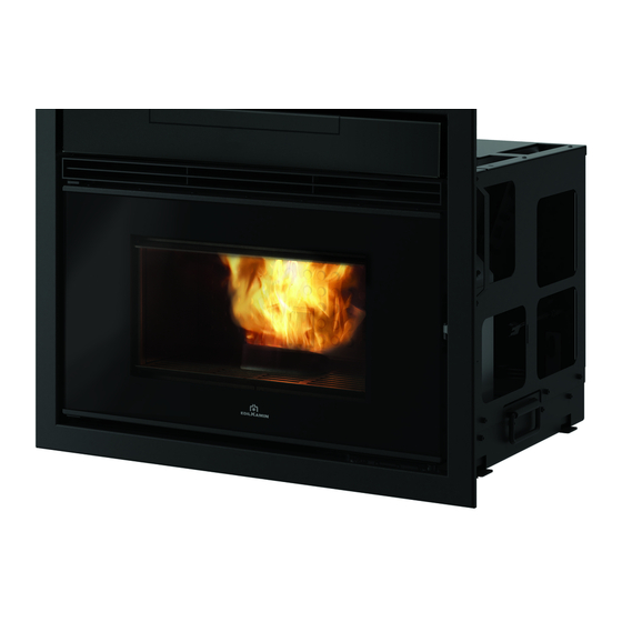
- Page 1 PELLKAMIN 12 PELLET FIREPLACE 805580 805590 805600 805610 Installation, use and maintenance...
-
Page 2: Table Of Contents
SERIAL NO.: Rating plate reference Performance declaration: (DoP - EK No. 137): Rating plate reference Moreover, the company hereby declares that: PELLKAMIN 12 complies with the requirements in the following European Directives: 2014/35/EC - Low Voltage Directive 2014/30/EC - Electromagnetic Compatibility Directive... - Page 3 Proper commissioning is required for activation of the Edilkamin warranty. The warranty is only valid in the MEANING OF SYMBOLS In some parts of the manual the following symbols country of sale of the product.
-
Page 4: Safety Information
DO NOT the warranty certificate inside the product: neither CLIMB ONTO THE PRODUCT OR USE IT AS A Edilkamin nor the reseller are liable for damage SUPPORT. Risk of damage and injury. resulting from incorrect installation or maintenance. - Page 5 DIMENSIONS PELLKAMIN 12 with ducted ventilation and a pellet loading trapdoor 87.5 Ø 8 smoke outlet Ø 15 trapdoor loading Ø 10 60.5 ducted air PELLKAMIN 12 with frontal ventilation and a pellet loading trapdoor 87.5 Ø 8 smoke outlet 60.5...
- Page 6 NOTES ON DIMENSIONS Example of minimum recommended dimensions for installation with fans at the bottom and optional stand at minimum height. This example for illustrative purposes only. Holes should also be made for: the fume discharge (flue); the combustion air inlet; ventilation air recovery (a 10x10 cm hole in the side of the covering) 30/40 18.5...
-
Page 7: Technical Data
2,4 GHz Logic board protection Fusibile T4A, 250 Vac 5x20 The above data are illustrative and are drawn from the certification by a notified body. EDILKAMIN s.p.a. reserves the right to modify the product without notification in the interests of improvement. -
Page 8: Unpacking
UNPACKING PREPARATION AND UNPACKING CONTENTS OF PACKAGE The packaging materials are neither toxic nor noxious The packaging varies according to the Pellkamin and do not require special disposal. version. The user is responsible for storing, disposing of and The packages are described in the “Packaging” recycling them in a regulatory fashion. - Page 9 UNPACKING , undo screws TO UNPACK THE PRODUCT (A) as shown below To facilitate handling, the Pellkamin 12 is fitted with handles (B). Do not use the air intake or fumes outlet to handle the appliance. This may lead to...
-
Page 10: Packaging
PACKAGING Pellkamin is available in four versions: 1. with ducted ventilation and a pellet loading trapdoor (see the fitting sections on “Ducted Ventilation” and “Load- ing Trapdoor”) 2. with frontal ventilation and a pellet loading trapdoor (see the fitting sections on “Frontal Ventilation Kit” and “Loading Trapdoor”) 3. - Page 11 PACKAGING The pack for the versions 2, 3 and 4 consist of two packages Version 2 with ducted ventilation and pellet loading trapdoor One package (1): • with the Pellkamin frame • the trapdoor loading system • the inlet surround •...
-
Page 12: Installation (Fume Discharge, Air Intake)
INSTALLATION SUMMARY INSTALLATION CHECKS For details, refer to the respective pages of this manual. Element to be checked What to check Suitability of the room • aeration • intended use: do not install in bedrooms, bathroom or fire hazard areas Volume of room •... - Page 13 • must have at most 3 bends, through an angle of wind, its safety equipment may switch the fireplace off. no more than 90° Contact the authorised Edilkamin Technical Assistance • must have a single horizontal section of length Centre.
- Page 14 INSTALLATION THE FLUE: EXTERNAL AIR INTAKE In general, we suggest two ways to ensure a proper Further to the general prescriptions for the fumes duct flow of combustion air. and flue, the flue: Air intake without direct connection to the •...
-
Page 15: Connections On The Terminal Boards
The electrical system must be compliant; check • the lower terminal board (high voltage) is for the the operation of the earth in particular. Edilkamin is electrical power and fan connections; not responsible for malfunctions resulting from an improperly grounded system. The power line must be these connections may be made by a of adequate section for the power of the appliance. -
Page 16: Fastening The Product And The Base (Optional)
INSTALLATION HEIGHT OF APPLIANCE MOUNTING TO THE BASE The Pellkamin can be mounted on an optional stand or Use the provided screws to secure the appliance to any other appropriate support the base OPTIONAL BASE Place the bottom of the base (1) in the desired position. -
Page 17: Pellet Loading Trapdoor
LOADING TRAPDOOR INSTALLING THE LOADING TRAPDOOR Step 1: INSTALLING THE LOADING HATCH Reinforce the plasterboard with metal profiles at the The loading kit includes: back. • loading tube • Make a hole 31 x 21 • loading inlet (A), with flange (B) for the loading •... -
Page 18: Ducted Ventilation
DUCTED VENTILATION INSTALLATION VENTILATION KIT The kit can be combined with each of the following Il Kit permette di portare aria calda nel locale di Edilkamin vents: installazione del prodotto o in altri locali col supporto • Split, with lighting due ventilatori. - Page 19 DUCTED VENTILATION INSTALLATION VENTILATION KIT NOTES 1. position the fan kit (A) after rotating it by 180° if • the Ø 100 mm connection section between the it is to be positioned to the left of the product, if product and the fan is a maximum 1.5 m. in length. necessary;...
- Page 20 DUCTED VENTILATION POSITION OF THE FAN IN THE KIT Positioning of the Fan Kit. This is a standard fan with upper vent and ready for Prepare a hole (H190 x L200) on the wall to house the use to the right of the product. fan kit.
-
Page 21: Frontal Ventilation Kit
5. position the top front panel of the frontal closure (4) and screw it on with one screw per side 6. the fan must then be activated by an Edilkamin Assistance Centre, using the reserved settings menu. VERSION WITH FRONTAL VENTILATION AND TRAPDOOR LOADING (2) - Page 22 FRONTAL VENTILATION KIT repeat on the other side (4 screws) VERSION WITH FRONTAL VENTILATION AND TRAPDOOR LOADING (2)
- Page 23 FRONTAL VENTILATION KIT Result with kit installed Self-tapping screw Screw for fixing the grille and fastening the top ceramic assembly front panel of the frontal closure (4) To ensure correct operation, it is essential that the technician adjusts the parameters according to the type of installation (also ducting or not), during the first ignition.
-
Page 24: Pellet Loading Drawer
PELLET LOADING DRAWER CONTENTS • Drawer Kit (2) • ceramic front panel with support (3) ASSEMBLY INSTRUCTIONS 1. unscrew the metal cover (1) on the top part of the frame 2. screw the ceramic front panel to the frame with its support (3). There are 5 screws in all (two on each side and one in the centre) 3. - Page 25 PELLET LOADING DRAWER repeat on the Connecting the pipes for ducting hot air other side (4 screws) Figure 11 Connecting Drawer fitted pipes for ducting Figure 12 hot air VERSION WITH DUCTED VENTILATION AND DRAWER (4)
- Page 26 4. position the snap fitted grille and ceramic assembly and secure it frontally with the self-tapping screw provided 5. the fan must then be activated by an Edilkamin Assistance Centre, using the reserved settings menu. VERSION WITH FRONTAL VENTILATION AND DRAWER (3)
- Page 27 DRAWER AND VENTILATION KIT Result with kit installed repeat on the other side (4 screws) Self-tapping screw for fixing the grille and ceramic assembly To ensure correct operation, it is essential that the technician adjusts the parameters according to the type of installation (also ducting or not), during the first ignition. The ventilation will not function properly if the technician does not adjust the parameters.
-
Page 28: Notes On Cladding
NOTES ON CLADDING INSTALLING THE CLADDING - PRECAUTIONS Regardless of the type of cladding (whether pre- existing or new) make sure that: • the compensation vents are present so that the mantel does not accumulate heat and damage the ventilation kit; •... -
Page 29: Fitting The Inlet Surround
INLET SURROUND For versions INLET SURROUND 2. with frontal ventilation and pellet loading trapdoor The inlet surround is used to fill the gap remaining (see fitting frontal ventilation Kit) between the fireplace frame and the cladding. 3. with frontal ventilation and pellet loading trapdoor The surround has an opening on one long side. -
Page 30: Instructions For Use
INSTALLATION FIRST IGNITION (COMMISSIONING) PHASES FUEL • Make sure you have read and understood this manual Use UNI EN ISO 17225-2 category A1 wood pellets • Remove all flammable materials from the appliance or similar regulatory products with the following (manuals, labels, etc.). - Page 31 USER INSTRUCTIONS OPERATION PHASES Further to the above operational procedures, the product has the following phases Description. The access to and adjustment of these functions is described below: - Ignition (display reads ON ) Flame ignites and grows stable Mode Size settings This is the result of: MANUAL...
- Page 32 • Open the back of the remote and use. Edilkamin and the reseller will not consider insert the two batteries in the indicated claims for battery life under any circumstances. If orientation.
- Page 33 USER INSTRUCTIONS The display reads the POSSIBLE STATES described below: - OFF STATE The fireplace is shutting off or is off in response to operation of the remote control’s ON/OFF key or an external contact (crono, phone dialler) The display shows the current time, room temperature and the status in relation to which the fireplace is OFF.
- Page 34 We describe the procedures below. In the event of the installation of the optional front fan, fans 2 and 3 will not be present and the Edilkamin technician will explain the new operating mode during ON/OFF installation.
- Page 35 USER INSTRUCTIONS - Stand by - Relax function When the Stand by function is active, in automatic Natural convection function with automatic power and timer modes, the product shuts off when the limiting. temperature setpoint is reached and turns on again This function is available in all modes: automatic, when the temperature drops.
- Page 36 USER INSTRUCTIONS Crono The following screen will appear. Scroll to “ENABLE” When the Crono function is active, the user sets a (underlined) using the “+/-” buttons. temperature setpoint and a time zone for which that To enable the Crono function to 7 days a week or setpoint is specified.
- Page 37 USER INSTRUCTIONS To combine one of the three temperatures To set the temperature setpoints (“TEMP” on to a time period (“SET” on the display), from the the display), from the Crono function, press the “OK” Crono function, press the “OK” button. The following button.
- Page 38 USER INSTRUCTIONS The second screen (accessible by pressing the “OK” To view/change the settings (“CHANGE” on button from the first screen) allows you to set the start the display), from the Crono function, press the “OK” button. The following screen will appear. and end time of the time period matching the chosen Scroll to “CHANGE”...
- Page 39 USER INSTRUCTIONS Night (deferred switching on/off) Load Pellets This function switches the product on/off after a set Allows you to load pellets after the screw feeder has emptied following a no-pellets alarm. period from activation of the function. Useful for the technician during commissioning. This is convenient if you go to bed and want the product Available only in the OFF state.
- Page 40 USER INSTRUCTIONS Date/Time Beep Sets the current date/time. Allows you to enable/disable the beep. This displays the first time the remote control is To access the function from the main menu (as activated with the stove powered on, or by selecting indicated in the Menu section above), press the M the option in the menu.
-
Page 41: Maintenance
MAINTENANCE Before doing any maintenance, disconnect Never vacuum hot ash, it can the appliance from the mains. make vacuum cleaner breakdown and represents a fire Regular maintenance essential risk. keeping the appliance in good working order. Do not empty the residue out into FAILURE TO SERVICE THE Fireplace WILL the pellet hopper. - Page 42 MAINTENANCE DAILY MAINTENANCE Note that using the fireplace without cleaning the grate can This must be done with the appliance switched off cause the gas in the combustion and cold. chamber to ignite and break the It must be done with a vacuum cleaner door glass.
- Page 43 SPARE PARTS For any spare parts, contact your reseller or technician. Using non-original spare parts may damage the appliance and relieves Edilkamin of all liability for damage resulting therefrom. DISPOSAL At the end of its service life, dispose of the product as required by regulations.
-
Page 44: Troubleshooting
TROUBLESHOOTING If problems occur, the fireplace shuts itself off automatically. The display will show the reason (see below). DO NOT disconnect the electrical power supply. To start the product up again, allow the shutdown procedure to complete, then press the remote control's ON/OFF button or the simplified ignition button. - Page 45 The battery symbol displays on the remote’s display if the battery is low. MAINTENANCE: A wrench symbol is shown on the display after 2000 hours of operation. The product is working, but it must be serviced by an authorised Edilkamin technician.
- Page 48 *941400-GB* w w w . e d i l k a m i n . c o m cod. 941400-GB 3.18/D...
Need help?
Do you have a question about the PELLKAMIN 12 and is the answer not in the manual?
Questions and answers