Table of Contents
Advertisement
Quick Links
Product information presented
here re fl ects con di tions at time
of publication. Consult factory
re gard ing dis crep an cies or
in con sis ten cies.
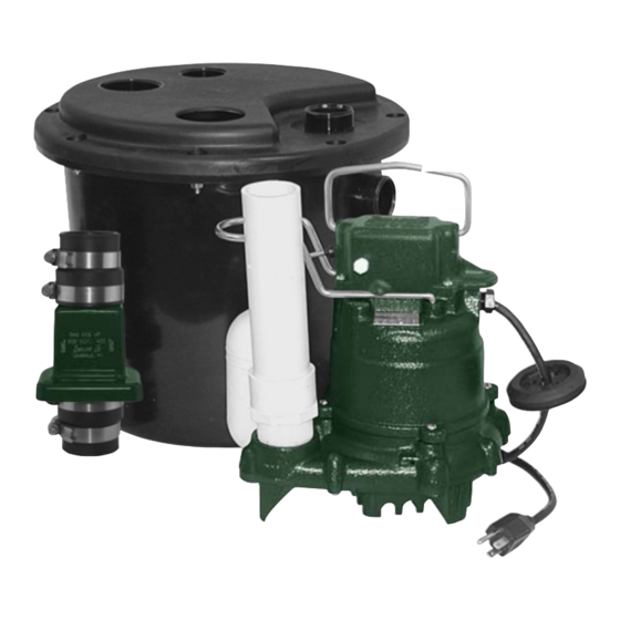
MODELS 104*, 105, 110, 115, 120, 131
Notice to Installer: Instructions must remain with installation.
1. Inspect your unit. Occasionally, prod ucts are dam aged during ship ment. If the unit is damaged, contact your dealer before using. DO NOT remove the test
plugs from the pump.
2. Care ful ly read the literature provided to familiarize yourself with specifi c details regarding installation and use. These ma te ri als should be re tained for future
reference.
SEE BELOW FOR LIST OF WARNINGS
1. To reduce the risk of elec tri cal shock, a prop er ly ground ed receptacle of
grounding type must be in stalled and pro tect ed by a ground fault circuit
in ter rupt er (GFCI) and in ac cor dance with National Elec tri cal Code and lo cal
codes.
(SEE WARNING BELOW)
2. Make certain that the receptacle is with in the reach of the pump's pow er
supply cord. DO NOT USE AN EX TEN SION CORD. Extension cords that
are too long or too light do not deliver suf fi cient voltage to the pump motor.
But more im por tant, they could present a safety hazard if the in su la tion were
to become damaged or the connection end were to fall into the sump.
3. Testing for Ground. As a safety mea sure, each elec tri cal outlet should be
checked for ground using an Un der writ ers Lab o ra to ry Listed cir cuit analyzer
which will in di cate if the pow er, neutral and ground wires are correctly con-
nect ed to your outlet. If they are not, call a qualifi ed electrician.
4. For Added Safety. Pump must be con nect ed to a 3-prong ground ed outlet
in ter rupt er de vice (ground fault circuit in ter rupt er).
5. FOR YOUR PROTECTION, ALWAYS DIS CON NECT PUMP FROM ITS
POWER SOURCE BE FORE HAN DLING. Single phase pumps are sup plied
with a 3-prong ground ed plug to help protect you against the possibility of
electrical shock. DO NOT, UNDER ANY CIR CUM STANC ES, RE MOVE THE
GROUND PIN. To re duce the risk of electrical shock, a properly grounded
re cep ta cle of ground ing type must be installed and pro tect ed by a ground
fault circuit interrupter (GFCI) in ac cor dance with national electrical code and
local codes.
6. Installation and checking of electrical cir cuits and hard ware should only be
performed by a qualifi ed licensed electrician.
7. Risk of electric shock - These pumps have not been in ves ti gat ed for use in
swimming pool areas.
8. According to the state of California (Prop 65), this product contains chemicals
known to the state of California to cause cancer and birth defects or other
reproductive harm.
MAIL TO: P.O. BOX 16347 • Louisville, KY 40256-0347
SHIP TO: 3649 Cane Run Road • Louisville, KY 40211-1961
(502) 778-2731 • 1 (800) 928-PUMP • FAX (502) 774-3624
DRAIN PUMP SYSTEMS
INSTALLATION IN STRUC TIONS
PREINSTALLATION CHECK LIST
© Copyright 2005 Zoeller Co. All rights reserved.
SEE BELOW FOR LIST OF CAUTIONS
1. Check to be sure your power source is adequate for handling the voltage
requirements of the motor, as in di cat ed on the pump or basin plate.
2. Make sure the pump electrical supply cir cuit is equipped with fuses or circuit
breakers of proper ca pac i ty. A sep a rate branch circuit is rec om mend ed, sized
according to the National Elec tri cal Code for the current shown on the pump
name plate.
3. All plumbing (discharge and vent lines) must be in stalled to meet local codes.
Unit must be vented. DO NOT USE AN AUTOMATIC PLUMBING VENT
DEVICE SIM I LAR TO A "PRO-VENT". Some states require this product to
be installed by a licensed plumber.
4. Repair and service should be performed by Zoeller Pump Com pa ny Au tho rized
Service Station only.
5. CHECK VALVE MUST BE USED TO REDUCE UN NEC ES SARY CYCLING
OF PUMP. Check valve must be purchased sep a rate ly on model 104 only.
6. Dewatering pumps are not designed or intended for han dling raw sewage.
7. Maximum operating temperature for 105-131 Drain Pumps must not exceed
130°F (54°C). 104 Drain Pumps are not to exceed 110°F (43°C).
8. For health reasons, do not unplug, turn off, or disable pump and use pump
tank system as a way to fi ll up a sink or laundry tray, etc.
9. Unit is designed for above ground installation only.
NOTE: Pumps with the "UL" mark and pumps with the "US" mark are tested to
UL Standard UL778. CSA Certifi ed pumps are certifi ed to CSA Standard
C22.2 No. 108.
REFER TO WARRANTY ON PAGE 2.
1
SECTION: 6.10.045
FM2336
Supersedes
visit our web site:
www.zoeller.com
MODEL:_______________________
DATE CODE: __________________
DATE INSTALLED: _____________
* MODEL 104 IS NOT
IAPMO APPROVED.
0905
New
Advertisement
Table of Contents

Related Manuals for Zoeller 104


Summary of Contents for Zoeller 104
- Page 1 3. Testing for Ground. As a safety mea sure, each elec tri cal outlet should be 4. Repair and service should be performed by Zoeller Pump Com pa ny Au tho rized checked for ground using an Un der writ ers Lab o ra to ry Listed cir cuit analyzer Service Station only.
-
Page 2: Limited Warranty
fi ttings or screws. If the above checklist does not uncover the problem, consult the factory - Do not attempt to service or otherwise disassemble pump. Service must be by Zoeller Authorized Service Stations. © Copyright 2005 Zoeller Co. All rights reserved. -
Page 3: Performance Characteristics
105/110 MODELS 104/132 115/120 Feet Meters Gal. Liters Gal. Liters Gal. Liters Shut-off Head: 18 ft. (5.5m) 19.25 ft. (5.9m) 23 ft. (7.0m) 009898 105/110/ 104/132 115/120 GALLONS LITERS FLOW PER MINUTE © Copyright 2005 Zoeller Co. All rights reserved. - Page 4 NOTE: If installing the internal trap, record the “x” dimension, it will be required in Step 4. INTERNAL TRAP COMPONENTS SUPPLIED BY OTHERS. PIPING SHOWN ONLY FOR CLARITY. X (4" MIN.) SEE NOTE Figure 1.1A INTERNAL TRAP PIPING SHOWN ONLY FOR CLARITY. Figure 1.1B STANDARD (EXTERNAL TRAP) SK2001 © Copyright 2005 Zoeller Co. All rights reserved.
- Page 5 Install the foam gasket into the “gasket seat” at the top of the basin, refer to Figure 3.1 for details. OVERLAP DETAIL FOAM GASKET APPROXIMATELY 1/4" OVERLAP GASKET SEAT DETAIL FOAM GASKET GASKET SEAT BASIN Figure 3.1 SK2003 © Copyright 2005 Zoeller Co. All rights reserved.
- Page 6 4 1/2" Figure 4.1 INLET TRAP FLANGED TAIL PIPE (SEE NOTE) Figure 4.2 TRAP DISCHARGE PARTIALLY VISIBLE THROUGH THE CORD SEAL OPENING. TAIL PIPE CORD SEAL OPENING DISCHARGE VENT Figure 4.3 SK2004 © Copyright 2005 Zoeller Co. All rights reserved.
-
Page 7: Final Assembly
6.5.) Check the discharge line for leaks as the pump empties the basin. 6.6.) Repeat steps 6.2 to 6.5 as necessary to insure proper operation. 6.7.) If problems persist refer to the troubleshooting guide located on page 2 of this manual. © Copyright 2005 Zoeller Co. All rights reserved. -
Page 8: Illustrated Parts Breakdown
N/A* N/A* O-Ring N/A* N/A* N/A* *When ordering this item order the hardware pack item #6. CHECK VALVE (PURCHASED SEPARATELY) SK2008A SK2008B Drain Pump 105 Pic tured Drain Pump 104 Pic tured © Copyright 2005 Zoeller Co. All rights reserved.
Need help?
Do you have a question about the 104 and is the answer not in the manual?
Questions and answers