Zoeller 105 Installation Instructions Manual
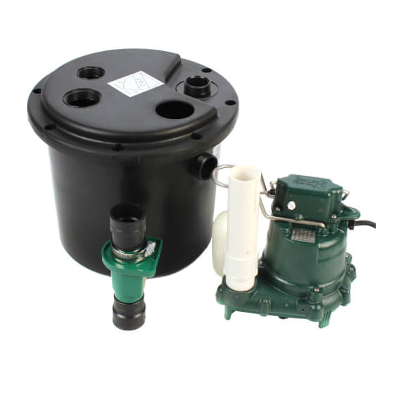
Drain pump system
Hide thumbs
Also See for 105:
- Installation instructions manual (8 pages) ,
- Installation instructions manual (9 pages) ,
- Installation instructions (4 pages)
Advertisement
Table of Contents
- 1 Safety Precautions
- 2 Service Checklist
- 3 Helpful Hints for Easy Installation
- 4 Do’s and Don't’s for Installing a Unit
- 5 Performance Characteristics
- 6 Determine Installation Configuration
- 7 Internal Trap
- 8 Standard (External Trap)
- 9 Install the Discharge Pipe Onto the Pump
- 10 Installation of the Gasket
- 11 Internal Trap Installation Only
- 12 Final Assembly
- 13 Initial Testing of Drain Basin System
- 14 Illustrated Parts Breakdown
- Download this manual
Notice to Installer: Instructions must remain with installation.
Your Peace of Mind is Our Top Priority
Product information presented
here reflects conditions at time
of publication. Consult factory
regarding discrepancies or
inconsistencies.
Notice to Installer: Instructions must remain with installation.
1. Inspect your unit. Occasionally, products are damaged during shipment. If the unit is damaged, contact your dealer before using. DO NOT remove the test
plugs from the pump.
2. Carefully read the literature provided to familiarize yourself with specific details regarding installation and use. These materials should be retained for future
reference.
SEE BELOW FOR LIST OF WARNINGS
1. To reduce the risk of electrical shock, a properly grounded receptacle of
grounding type must be installed and protected by a ground fault circuit
interrupter (GFCI) and in accordance with National Electrical Code and local
codes.
2. Make certain that the receptacle is within the reach of the pump's power
supply cord. DO NOT USE AN EXTENSION CORD. Extension cords that
are too long or too light do not deliver sufficient voltage to the pump motor
and could present a safety hazard if the insulation were to become damaged
or the connection end were to fall into the sump.
3. Testing for Ground. As a safety measure, each electrical outlet should be
checked for ground using an Underwriters Laboratory Listed circuit analyzer
which will indicate if the power, neutral and ground wires are correctly con-
nected to your outlet. If they are not, call a qualified electrician.
4. For Added Safety. Pump must be connected to a 3-prong grounded outlet
interrupter device (ground fault circuit interrupter).
5. FOR YOUR PROTECTION, ALWAYS DISCONNECT PUMP FROM ITS
POWER SOURCE BEFORE HANDLING. Single phase pumps are supplied
with a 3-prong grounded plug to help protect you against the possibility of
electrical shock. DO NOT, UNDER ANY CIRCUMSTANCES, REMOVE THE
GROUND PIN. To reduce the risk of electrical shock, a properly grounded
receptacle of grounding type must be installed and protected by a ground
fault circuit interrupter (GFCI) in accordance with national electrical code and
local codes.
6. Installation and checking of electrical circuits and hardware should only be
performed by a qualified, licensed electrician.
7. Risk of electric shock - These pumps have not been investigated for use in
swimming pool areas.
1. Check to be sure your power source is adequate for handling the voltage
®
MAIL TO: P.O. BOX 16347 • Louisville, KY 40256-0347
SHIP TO: 3649 Cane Run Road • Louisville, KY 40211-1961
TEL: (502) 778-2731 • 1 (800) 928-PUMP • FAX: (502) 774-3624
DRAIN PUMP SYSTEM
MODEL 105 (Korean)
INSTALLATION INSTRUCTIONS
PREINSTALLATION CHECKLIST
© Copyright 2017 Zoeller
CAUTION
SEE BELOW FOR LIST OF CAUTIONS
requirements of the motor, as indicated on the pump or basin plate.
2. Make sure the pump electrical supply circuit is equipped with fuses or circuit
breakers of proper capacity. A separate branch circuit is recommended, sized
according to the National Electrical Code and local codes for the current
shown on the pump name plate.
3. All plumbing (discharge and vent lines) must be installed to meet local codes.
Unit must be vented. DO NOT USE AN AUTOMATIC PLUMBING VENT
DEVICE SIMILAR TO A "PRO-VENT". Some states require this product to
be installed by a licensed plumber.
4. Repair and service should be performed by Zoeller Pump Company Authorized
Service Station only.
5. CHECK VALVE MUST BE USED TO REDUCE UNNECESSARY CYCLING
OF PUMP.
6. Dewatering pumps are not designed or intended for handling raw sewage.
7. Maximum operating temperature for 105 Drain Pumps must not exceed
54 °C (130 °F).
8. For health reasons, do not unplug, turn off, or disable pump and use pump
tank system as a way to fill up a sink or laundry tray, etc.
9. Unit is designed for above ground installation only.
REFER TO WARRANTY ON PAGE 2.
Co. All rights reserved.
®
1
60 Hz
Visit our web site:
www.zoellerpumps.com
MODEL:_______________________
DATE CODE: __________________
DATE INSTALLED: _____________
FM3034_Ea
0717
Supersedes
New
Advertisement
Table of Contents

Related Manuals for Zoeller 105


Summary of Contents for Zoeller 105
- Page 1 3. Testing for Ground. As a safety measure, each electrical outlet should be 4. Repair and service should be performed by Zoeller Pump Company Authorized checked for ground using an Underwriters Laboratory Listed circuit analyzer Service Station only.
- Page 2 If the above checklist does not uncover the problem, consult the factory - Do not attempt to service or otherwise disassemble pump. Service must be by Zoeller Authorized Service Stations. © Copyright 2017 Zoeller Co. All rights reserved.
- Page 3 Performance Characteristics PUMP PERFORMANCE CURVE MODEL 53 TOTAL DYNAMIC HEAD/FLOW PER MINUTE EFFLUENT AND DEWATERING MODEL Feet Meters Gal. Liters Shut-off Head: 19.25 ft.(5.9m) 009897 GALLONS LITERS FLOW PER MINUTE © Copyright 2017 Zoeller Co. All rights reserved. ®...
- Page 4 INTERNAL TRAP COMPONENTS SUPPLIED BY OTHERS. PIPING SHOWN ONLY FOR CLARITY. X (102 mm MIN.) SEE NOTE Figure 1.1A INTERNAL TRAP PIPING SHOWN ONLY FOR CLARITY. Figure 1.1B STANDARD (EXTERNAL TRAP) SK2001 © Copyright 2017 Zoeller Co. All rights reserved. ®...
- Page 5 Figure 2.1 SK2002 STEP 3 Installation of the Gasket 3.1) Install the gasket into the “gasket seat” at the top of the basin. OVERLAP DETAIL FOAM GASKET APPROXIMATELY 1/4" OVERLAP GASKET SEAT DETAIL FOAM GASKET GASKET SEAT BASIN Figure 3.1 SK3160 © Copyright 2017 Zoeller Co. All rights reserved. ®...
- Page 6 115 mm INLET Figure 4.1 TRAP FLANGED TAIL PIPE (SEE NOTE) Figure 4.2 TRAP DISCHARGE PARTIALLY VISIBLE THROUGH THE CORD SEAL OPENING. TAIL PIPE CORD SEAL OPENING DISCHARGE VENT Figure 4.3 SK2004 © Copyright 2017 Zoeller Co. All rights reserved. ®...
- Page 7 INTERNAL TRAP INSTALLATION STANDARD INSTALLATION Figure 5.3A Figure 5.3B SK2006 STEP 6 Initial Testing of Drain Basin System 6.1) Plug the cord into a properly grounded GFCI receptacle. 6.2) Fill tank with water. 6.3) Check all plumbing for leaks as the basin fills. 6.4) Verify that the pump starts and stops. 6.5.) Check the discharge line for leaks as the pump empties the basin. 6.6.) Repeat steps 6.2 to 6.5 as necessary to insure proper operation. 6.7.) If problems persist refer to the troubleshooting guide located on page 2 of this manual. © Copyright 2017 Zoeller Co. All rights reserved. ®...
- Page 8 1. Hardware pack consist of (8) 1/4"-20 x 1-1/8" long round head stainless steel machine screws, (8) #1/4"-20 stainless steel hex nuts and (16) 1/4" flat stainless steel washers along with (1) pipe cap and (1) o-ring and (1) pipe seal. MODEL 105 (KOREAN) SK3161 Original Installation Instructions © Copyright 2017 Zoeller...
Need help?
Do you have a question about the 105 and is the answer not in the manual?
Questions and answers