Zoeller 105 Installation Instructions
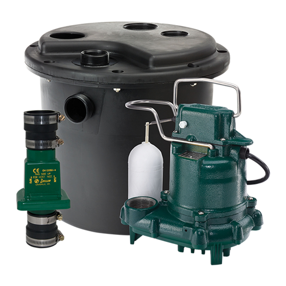
Preassembled drain pump system
Hide thumbs
Also See for 105:
- Installation instructions manual (8 pages) ,
- Installation instructions manual (9 pages) ,
- Installation instructions manual (9 pages)
Advertisement
Quick Links
Trusted. Tested. Tough.
MODEL: ______________________
DATE CODE: __________________
DATE INSTALLED: _____________
Product information presented here reflects conditions at time of publication. Consult factory regarding discrepancies or inconsistencies.
Notice to Installer: Instructions must remain with installation.
1. Inspect your unit. Occasionally, products are damaged during shipment. If the unit is damaged, contact your dealer before using. DO NOT remove the test plugs
from the pump.
2. Carefully read the literature provided to familiarize yourself with specific details regarding installation and use. These materials should be retained for future
reference.
SEE BELOW FOR LIST OF WARNINGS
1. To reduce the risk of electrical shock, a properly grounded receptacle of
grounding type must be installed and protected by a ground fault circuit
interrupter (GFCI) and in accordance with National Electrical Code and local
codes. (SEE WARNING BELOW).
2. Make certain that the receptacle is within the reach of the pump's power
supply cord. DO NOT USE AN EXTENSION CORD. Extension cords that are too
long or too light do not deliver sufficient voltage to the pump motor. But more
important, they could present a safety hazard if the insulation were to become
damaged or the connection end were to fall into the sump.
3. Testing for Ground. As a safety measure, each electrical outlet should be checked
for ground using an Underwriters Laboratory Listed circuit analyzer which will
indicate if the power, neutral and ground wires are correctly connected to your
outlet. If they are not, call a qualified electrician.
4. For Added Safety. Pump must be connected to a 3-prong grounded outlet
interrupter device (ground fault circuit interrupter).
5. FOR YOUR PROTECTION, ALWAYS DISCONNECT PUMP FROM ITS POWER SOURCE
BEFORE HANDLING. Single phase pumps are supplied with a 3-prong grounded
plug to help protect you against the possibility of electrical shock. DO NOT,
UNDER ANY CIRCUMSTANCES, REMOVE THE GROUND PIN. To reduce the risk of
electrical shock, a properly grounded receptacle of grounding type must be
installed and protected by a ground fault circuit interrupter (GFCI) in accordance
with national electrical code and local codes.
6. Installation and checking of electrical circuits and hardware should only be
performed by a qualified licensed electrician.
7. Risk of electric shock - These pumps have not been investigated for use in
swimming pool areas.
8. Prop65 Warning for California residents:
: Cancer and Reproductive Harm-
www.P65Warning.ca.gov.
®
MAIL TO: P.O. BOX 16347 • Louisville, KY 40256-0347
SHIP TO: 3649 Cane Run Road • Louisville, KY 40211-1961
Tel: (502) 778-2731 • 1 (800) 928-PUMP
PREASSEMBLED DRAIN PUMP SYSTEM
MODELS 105 and 132
INSTALLATION INSTRUCTIONS
© Copyright 2020 Zoeller
CAUTION
SEE BELOW FOR LIST OF CAUTIONS
1. Check to be sure your power source is adequate for handling the voltage
requirements of the motor, as indicated on the pump or basin plate.
2. Make sure the pump electrical supply circuit is equipped with fuses or circuit
breakers of proper capacity. A separate branch circuit is recommended, sized
according to the National Electrical Code for the current shown on the pump
name plate.
3. All plumbing (discharge and vent lines) must be installed to meet local codes.
Unit must be vented. Some states require this unit to be installed by a qualified
licensed plumber. DO NOT USE AN AUTOMATIC PLUMBING VENT DEVICE SIMILAR
TO A "PRO-VENT".
4. Repair and service should be performed by Zoeller Pump Company Authorized
Service and warranty center only.
5. CHECK VALVE MUST BE USED TO REDUCE UNNECESSARY CYCLING OF PUMP.
6. Dewatering pumps are not designed or intended for handling raw
sewage.
7. Maximum operating temperature for 132 Drain Pumps must not exceed 110 °F
(43 °C). Model 105 rated for 130 °F (54 °C).
8. For health reasons, do not unplug, turn off, or disable pump and use pump tank
system as a way to fill up a sink or laundry tray, etc.
NOTE: Pumps with the "UL" mark and pumps with the "US" mark are
tested to UL Standard UL778. CSA Certified pumps are certified to CSA
Standard C22.2 No. 108.
REFER TO WARRANTY ON PAGE 2.
Co. All rights reserved.
®
FM2113
0320
Supersedes
1019
Visit our website:
zoellerpumps.com
Register your
Zoeller Pump Company
Product on our website:
http://reg.zoellerpumps.com/
Advertisement

Subscribe to Our Youtube Channel
Related Manuals for Zoeller 105


Summary of Contents for Zoeller 105
- Page 1 5. FOR YOUR PROTECTION, ALWAYS DISCONNECT PUMP FROM ITS POWER SOURCE 7. Maximum operating temperature for 132 Drain Pumps must not exceed 110 °F BEFORE HANDLING. Single phase pumps are supplied with a 3-prong grounded (43 °C). Model 105 rated for 130 °F (54 °C). plug to help protect you against the possibility of electrical shock. DO NOT, 8. For health reasons, do not unplug, turn off, or disable pump and use pump tank UNDER ANY CIRCUMSTANCES, REMOVE THE GROUND PIN.
- Page 2 G. If tank or fittings leak. tighten fittings or screws. If the above checklist does not uncover the problem, consult the factory - Do not attempt to service or otherwise disassemble pump. Service must be by Zoeller Authorized Service Stations. © Copyright 2020 Zoeller Co. All rights reserved.
- Page 3 FLOW PER MINUTE STEP 1 Determine Installation Configuration NOTE: This preassembled unit is designed for use with an external trap. Figure 1 is a typical configuration for installation of the drain system. The actual configuration will vary depending on your cabinet and sink configuration. PIPING SHOWN ONLY FOR CLARITY. Figure 1 STANDARD INSTALLATION SK2001 © Copyright 2020 Zoeller Co. All rights reserved. ®...
- Page 4 Basin 013017 013017 013017 Discharge pipe 013732 150861 156360 Basin cover 013018 013018 013018 Hardware pack 152620 152620 152620 132-A/B Basin seal 152607 152607 152607 Check valve 30-0181 019768 019768 Notes: 1. Hardware pack consists of (8) 1/4" - 20 x 1-1/4" long hex washer stainless steel machine screws, (8) #1/4" - 20 hex flange stainless steel hex nuts along with (1) pipe cap, (1) O-ring, and (1) basin seal. SK2833 © Copyright 2020 Zoeller Co. All rights reserved. ®...
Need help?
Do you have a question about the 105 and is the answer not in the manual?
Questions and answers