Table of Contents
Advertisement
Quick Links
Your Peace of Mind is Our Top Priority
Product information presented
here reflects conditions at time
of publication. Consult factory
regarding discrepancies or
inconsistencies.
Notice to Installer: Instructions must remain with installation.
1. Inspect your unit. Occasionally, products are damaged during shipment. If the unit is damaged, contact your dealer before using.
DO NOT remove the test plugs from the pump.
2. Carefully read the literature provided to familiarize yourself with specific details regarding installation and use. These materials
should be retained for future reference.
SEE BELOW FOR LIST OF WARNINGS
1. To reduce the risk of electrical shock, a properly grounded
receptacle of grounding type must be installed and protected
by a ground fault circuit interrupter (GFCI) and in accordance
with National Electrical Code and local codes.
(SEE WARNING BELOW)
2. Make certain that the receptacle is within the reach of the
pump's power supply cord. DO NOT USE AN EXTENSION
CORD. Extension cords that are too long or too light do not
deliver sufficient voltage to the pump motor. But more impor-
tant, they could present a safety hazard if the insulation were
to become damaged or the connection end were to fall into the
sump.
3. Testing for Ground. As a safety measure, each electrical outlet
should be checked for ground using an Underwriters Laboratory
Listed circuit analyzer which will indicate if the power, neutral
and ground wires are correctly connected to your outlet. If they
are not, call a qualified electrician.
4. For Added Safety. Pump must be connected to a 3-prong
grounded outlet interrupter device (ground fault circuit inter-
rupter).
5. FOR YOUR PROTECTION, ALWAYS DISCONNECT PUMP
FROM ITS POWER SOURCE BEFORE HANDLING. Single
phase pumps are supplied with a 3-prong grounded plug to help
protect you against the possibility of electrical shock. DO NOT,
UNDER ANY CIRCUMSTANCES, REMOVE THE GROUND
PIN. To reduce the risk of electrical shock, a properly grounded
receptacle of grounding type must be installed and protected
by a ground fault circuit interrupter (GFCI) in accordance with
national electrical code and local codes.
6. Installation and checking of electrical circuits and hardware
should only be performed by a qualified licensed electrician.
7. Risk of electric shock - These pumps have not been investigated
for use in swimming pool areas.
8. According to the state of California (Prop. 65), this product
contains chemicals known to the state of California to cause
cancer and birth defects or other reproductive harm.
®
®
MAIL TO: P.O. BOX 16347 • Louisville, KY 40256-0347
SHIP TO: 3649 Cane Run Road • Louisville, KY 40211-1961
(502) 778-2731 • 1 (800) 928-PUMP • FAX (502) 774-3624
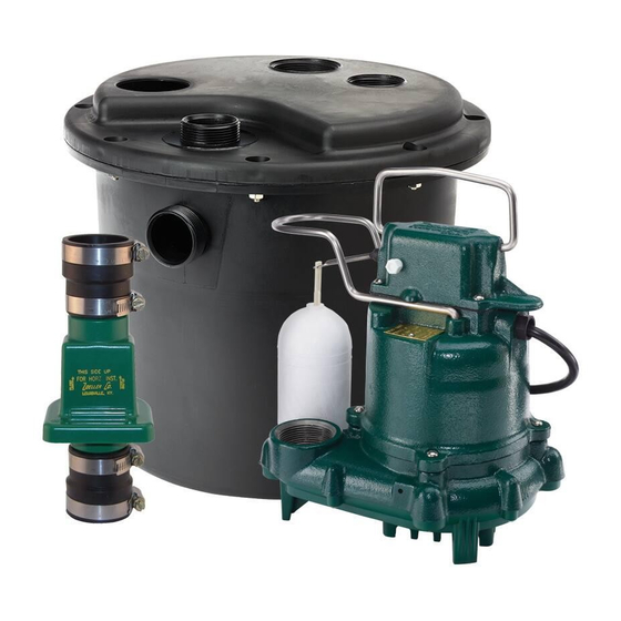
2" INLET / HIGH HEAD
DRAIN PUMP SYSTEMS
MODELS 105-0010, 135-0005
INSTALLATION INSTRUCTIONS
PREINSTALLATION CHECKLIST
© Copyright 2014 Zoeller Co. All rights reserved.
CAUTION
SEE BELOW FOR LIST OF CAUTIONS
1. Check to be sure your power source is adequate for handling
the voltage requirements of the motor, as indicated on the pump
or basin plate.
2. Make sure the pump electrical supply circuit is equipped with
fuses or circuit breakers of proper capacity. A separate branch
circuit is recommended, sized according to the National Electri-
cal Code for the current shown on the pump name plate.
3. All plumbing (discharge and vent lines) must be installed to meet
local codes. Unit must be vented. DO NOT USE AN AUTOMATIC
PLUMBING VENT DEVICE SIMILAR TO A "PRO-VENT".
Some states require this product to be installed by a licensed
plumber.
4. Repair and service should be performed by Zoeller Pump
Company Authorized Service Station only.
5. CHECK VALVE MUST BE USED TO REDUCE UNNECESSARY
CYCLING OF PUMP.
6. Dewatering pumps are not designed or intended for handling
raw sewage.
7. Maximum operating temperature for 105-0010 and 135-0005
Drain Pumps must not exceed 130° F (54° C).
8. For health reasons, do not unplug, turn off, or disable pump
and use pump tank system as a way to fill up a sink or laundry
tray, etc.
NOTE: Pumps with the "UL" mark and pumps with the "US" mark
are tested to UL Standard UL778. CSA Certified pumps are
certified to CSA Standard C22.2 No. 108.
REFER TO WARRANTY ON PAGE 2.
1
FM2170
Supersedes
visit our web site:
www.zoeller.com
MODEL:_______________________
DATE CODE: __________________
DATE INSTALLED: _____________
0114
0703
Advertisement
Table of Contents

Subscribe to Our Youtube Channel
Related Manuals for Zoeller 105-0010


Summary of Contents for Zoeller 105-0010
- Page 1 3. Testing for Ground. As a safety measure, each electrical outlet 4. Repair and service should be performed by Zoeller Pump should be checked for ground using an Underwriters Laboratory Company Authorized Service Station only. Listed circuit analyzer which will indicate if the power, neutral 5.
- Page 2 Zoeller Pump Company warrants, to the purchaser and subsequent or implied; and we do not authorize any representative or other person owner during the warranty period, every new Zoeller Pump Company to assume for us any other liability in connection with our products.
- Page 3 PER MINUTE PUMP PERFORMANCE CURVE MODELS 105/135 EFFLUENT AND DEWATERING MODEL Feet Meters Gal. Liters Gal. Liters Shut-off Head: 19.25 ft. (5.9m) 38 ft. (11.6m) 016301B GALLONS LITERS FLOW PER MINUTE 016301A © Copyright 2014 Zoeller Co. All rights reserved.
- Page 4 BE SURE THAT WEEPHOLE IMPORTANT IS NOT DIRECTED TOWARD THE FLOAT! Water stream will be visible from this hole during pump run periods. PUMP DISCHARGE Figure 2.1 Note: Model 105 shown. SK2002B © Copyright 2012 Zoeller Co. All rights reserved.
- Page 5 4.1) Install the foam gasket on to the “gasket surface” at the top of the basin, refer to Figure 4.1 for details. FOAM GASKET OVERLAP DETAIL APPROXIMATELY 6 mm (1/4") OVERLAP GASKET SEAL DETAIL FOAM GASKET GASKET SURFACE BASIN GASKET SEAL MUST BE PLACED INSIDE OF HOLE Figure 4.1 SK2368 © Copyright 2014 Zoeller Co. All rights reserved.
- Page 6 Check the discharge line for leaks as the pump empties the basin. Repeat steps 6.2 to 6.5 as necessary to ensure proper operation. If problems persist refer to the troubleshooting guide located on page 2 of this manual. © Copyright 2012 Zoeller Co. All rights reserved.
- Page 7 Discharge Tube 004400 013732 013732 Hardware Pack 007725 007725 007725 Basin Seal 006302 006302 006302 Check valve 30-0181 Union/Check valve “Combo” 30-0102 30-0102 Drain Pump 105-0010 Shown Drain Pump 135-0005 Shown SK2373 SK2373 © Copyright 2014 Zoeller Co. All rights reserved.
- Page 8 MAIL TO: P.O. BOX 16347 • Louisville, KY 40256-0347 SHIP TO: 3649 Cane Run Road • Louisville, KY 40211-1961 visit our web site: (502) 778-2731 • 1 (800) 928-PUMP • FAX (502) 774-3624 ® www.zoeller.com Your Peace of Mind is Our Top Priority ®...
Need help?
Do you have a question about the 105-0010 and is the answer not in the manual?
Questions and answers