Table of Contents
Advertisement
Quick Links
Advertisement
Chapters
Table of Contents
Troubleshooting

Related Manuals for Suzuki GSF600Y 2000


Summary of Contents for Suzuki GSF600Y 2000
- Page 1 GSF600S/GSF600 9 9 5 0 0 - 3 6 1 0 2 - 0 1 E...
-
Page 2: Table Of Contents
FOREWORD GROUP INDEX This manual contains an introductory description on the SUZUKI GSF600S and procedures for its inspection/service and overhaul of its main com- GENERAL INFORMATION ponents. Other information considered as generally known is not included. PERIODIC MAINTENANCE Read the GENERAL INFORMATION section to fa- miliarize yourself with the motorcycle and its main- tenance. -
Page 3: How To Use This Manual
HOW TO USE THIS MANUAL TO LOCATE WHAT YOU ARE LOOKING FOR: 1. The text of this manual is divided into sections. 2. The section titles are listed in the GROUP INDEX. 3. Holding the manual as shown at the right will allow you to find the first page of the section easily. - Page 4 Apply oil. Use engine oil unless Apply or use brake fluid. otherwise specified. Apply molybdenum oil solution (mix- ture of engine oil and SUZUKI MOLY Measure in voltage range. PASTE in a ratio of 1:1). Apply SUZUKI SUPER GREASE “A”.
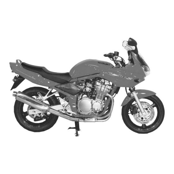
- Page 5 GENERAL INFORMATION CONTENTS WARNING/CAUTION/NOTE ............. 1- 2 GENERAL PRECAUTIONS .............. 1- 2 SUZUKI GSF600SY (2000-MODEL) ..........1- 4 SERIAL NUMBER LOCATION ............1- 4 FUEL AND OIL RECOMMENDATION ..........1- 4 FUEL ....................1- 4 ENGINE OIL ................... 1- 5 BRAKE FLUID ................
-
Page 6: Warning/Caution/Note
1-2 GENERAL INFORMATION WARNING/CAUTION/NOTE Please read this manual and follow its instructions carefully. To emphasize special information, the symbol and the words WARNING, CAUTION and NOTE have special meanings. Pay special attention to the mes- sages highlighted by these signal words. Indicates a potential hazard that could result in death or injury. - Page 7 GENERAL INFORMATION 1-3 " * If parts replacement is necessary, replace the parts with Suzuki Genuine Parts or their equiva- lent. * When removing parts that are to be reused, keep them arranged in an orderly manner so that they may be reinstalled in the proper order and orientation.
-
Page 8: Suzuki Gsf600Sy (2000-Model)
) method or 91 octane or higher rated by the research method. 2. Suzuki recommends that customers use alcohol free, unleaded gasoline whenever possible. 3. Use of blended gasoline containing MTBE (Methyl Tertiary Butyl Ether) is permitted. 4. Use of blended gasoline/alcohol fuel is permitted, provided that the fuel contains not more than 10% etha- nol. -
Page 9: Engine Oil
GENERAL INFORMATION 1-5 ENGINE OIL Use a premium quality 4-stroke motor oil to ensure longer ser- vice life of your motorcycle. Use only oils which are rated SF or SG under the API service classification. MULTIGRADE The recommended viscosity is SAE 10W-40. If an SAE 10W-40 motor oil is not available, select an alternative according to the right chart. -
Page 10: Information Labels
1-6 GENERAL INFORMATION INFORMATION LABELS (Attached on the left frame pipe) (Attached on the right side of the rear fender) (Except E-03, 33) 5 mm (0.2 in) 10 mm 10 mm Document tray (0.4 in) (0.4 in) 10 mm 10 mm (0.4 in) (0.4 in) (E-28 Only) -
Page 11: Specifications
GENERAL INFORMATION 1-7 SPECIFICATIONS DIMENSIONS AND DRY MASS Overall length ..............2 060 mm (81.1 in) Overall width ..............770 mm (30.3 in) Overall height ..............1 220 mm (48.0 in) Wheelbase ..............1 440 mm (56.7 in) Ground clearance ............130 mm (5.1 in) Seat height .............. - Page 12 1-8 GENERAL INFORMATION CHASSIS Front suspension ............Telescopic, coil spring, oil damped Rear suspension ............Link type, gas/oil damped, coil spring, spring pre- load 7-way adjustable, rebound damping force 4- way adjustable Steering angle .............. 35° (right & left) Caster ................25°...
-
Page 13: Country Or Area Codes
GENERAL INFORMATION 1-9 COUNTRY OR AREA CODES The following codes stand for the applicable country(-ies) and area(-s). CODE COUNTRY or AREA E-02 England (UK) E-19 European markets E-24 Australia E-28 Canada... - Page 14 PERIODIC MAINTENANCE 2-1 PERIODIC MAINTENANCE 2-1 PERIODIC MAINTENANCE 2-1 PERIODIC MAINTENANCE 2-1 PERIODIC MAINTENANCE 2-1 PERIODIC MAINTENANCE CONTENTS PERIODIC MAINTENANCE SCHEDULE ..........2- 2 PERIODIC MAINTENANCE CHART ..........2- 2 LUBRICATION POINTS ..............2- 3 MAINTENANCE AND TUNE-UP PROCEDURES ......... 2- 4 VALVE CLEARANCE ..............
-
Page 15: Periodic Maintenance Schedule
2-2 PERIODIC MAINTENANCE PERIODIC MAINTENANCE SCHEDULE The chart below lists the recommended intervals for all the required periodic service work necessary to keep the motorcycle operating at peak performance and economy. Maintenance intervals are expressed in terms of kilometers, miles and months, and are dependant on whichever comes first. NOTES: More frequent servicing may be performed on motorcycles that are used under severe conditions. -
Page 16: Lubrication Points
PERIODIC MAINTENANCE 2-3 PERIODIC MAINTENANCE 2-3 PERIODIC MAINTENANCE 2-3 PERIODIC MAINTENANCE 2-3 PERIODIC MAINTENANCE 2-3 LUBRICATION POINTS Proper lubrication is important for smooth operation and long life of each working part of the motorcycle. Major lubrication points are indicated below. !"... -
Page 17: Maintenance And Tune-Up Procedures
2-4 PERIODIC MAINTENANCE MAINTENANCE AND TUNE-UP PROCEDURES This section describes the servicing procedures for each item mentioned in the Periodic Maintenance chart. VALVE CLEARANCE Inspect initially at 1 000 km (600 miles, 1 month) and ev- ery 12 000 km (7 500 miles, 12 months). •... -
Page 18: Spark Plugs
($3-47) ( 99000-31140: SUZUKI BOND “1207B” • Tighten the cylinder head cover bolts to the specified torque. ) Cylinder head cover bolt: 14 N . m (1.4 kgf . m, 10.0 lb-ft) •... - Page 19 2-6 PERIODIC MAINTENANCE NOTE: If it is difficult to remove any of the spark plug caps, pry them up using a screwdriver. & 09930-10121: Spark plug wrench set 09900-20803: Thickness gauge Standard Cold type Hot type CR9EK CR10EK CR8EK DENSO U27ETR U31ETR U24ETR...
-
Page 20: Exhaust Pipe Bolts And Muffler Bolts
PERIODIC MAINTENANCE 2-7 PERIODIC MAINTENANCE 2-7 PERIODIC MAINTENANCE 2-7 PERIODIC MAINTENANCE 2-7 PERIODIC MAINTENANCE 2-7 EXHAUST PIPE BOLTS AND MUFFLER BOLTS Tighten initially at 1 000 km (600 miles, 1 month) and ev- ery 12 000 km (7 500 miles, 12 months) thereafter. •... - Page 21 2-8 PERIODIC MAINTENANCE • Reinstall the cleaned or new air cleaner element in the re- verse order of removal. • When installing the air cleaner element into the air cleaner case, make sure that the * mark A points up. If driving under dusty conditions, clean the air cleaner element more frequently.
-
Page 22: Engine Oil And Oil Filter
PERIODIC MAINTENANCE 2-9 PERIODIC MAINTENANCE 2-9 PERIODIC MAINTENANCE 2-9 PERIODIC MAINTENANCE 2-9 PERIODIC MAINTENANCE 2-9 ENGINE OIL AND OIL FILTER (ENGINE OIL) Replace initially at 1 000 km (600 miles, 1 month) and every 6 000 km (4 000 miles, 6 months) thereafter. (OIL FILTER) Replace initially at 1 000 km (600 miles, 1 month) and every 18 000 km (11 000 miles, 18 months) thereafter. -
Page 23: Fuel Hose
Other manufacturer’s oil filters may differ in thread speci- fications (thread diameter and pitch), filtering perfor- mance and durability which may lead to engine damage or oil leaks. Also, do not use a genuine Suzuki automo- bile oil filter on this motorcycle. FUEL HOSE Inspect every 6 000 km (4 000 miles, 6 months). -
Page 24: Fuel Filter
PERIODIC MAINTENANCE 2-11 PERIODIC MAINTENANCE 2-11 PERIODIC MAINTENANCE 2-11 PERIODIC MAINTENANCE 2-11 PERIODIC MAINTENANCE 2-11 FUEL FILTER Inspect every 6 000 km (4 000 miles, 6 months) and re- place every 12 000 km (7 500 miles, 12 months). • Remove the fuel tank. ($4-3) Check the fuel filter for evidence of dirt and contamination. -
Page 25: Carburetor Synchronization
2-12 PERIODIC MAINTENANCE 2nd step: • Loosen the locknut 1 of the throttle pulling cable 2. • Turn the adjuster 3 in or out until the throttle cable play (at the throttle grip) A is between 2 – 4 mm (0.08 – 0.16 in). •... -
Page 26: Pair (Air Supply) System
PERIODIC MAINTENANCE 2-13 PERIODIC MAINTENANCE 2-13 PERIODIC MAINTENANCE 2-13 PERIODIC MAINTENANCE 2-13 PERIODIC MAINTENANCE 2-13 PAIR (AIR SUPPLY) SYSTEM Inspect every 12 000 km (7 500 miles, 12 months). ($3-98) CLUTCH CABLE PLAY Inspect every 6 000 km (4 000 miles, 6 months). •... -
Page 27: Drive Chain
2-14 PERIODIC MAINTENANCE DRIVE CHAIN Inspect initially at 1 000 km (600 miles, 1 month) and ev- Grease ery 6 000 km (4 000 miles, 6 months) thereafter. “O” ring Lubricate every 1 000 km (600 miles). With the transmission in neutral, support the motorcycle using the center-stand and turn the rear wheel slowly by hand. - Page 28 * Do not use any oil sold commercially as “drive chain oil”. Such oil can damage the O-rings. * The standard drive chain is a RK50MFOZ1. SUZUKI recommends to use this standard drive chain as a re- placement.
-
Page 29: Brakes
2-16 PERIODIC MAINTENANCE BRAKES (BRAKE) Inspect initially at 1 000 km (600 miles, 1 month) and ev- ery 6 000 km (4 000 miles, 6 months) thereafter. (BRAKE HOSE AND BRAKE FLUID) Inspect every 6 000 km (4 000 miles, 6 months). Replace hoses every 4 years. - Page 30 PERIODIC MAINTENANCE 2-17 PERIODIC MAINTENANCE 2-17 PERIODIC MAINTENANCE 2-17 PERIODIC MAINTENANCE 2-17 PERIODIC MAINTENANCE 2-17 BRAKE PADS The extent of brake pad wear can be checked by observing the grooved limit line 1 on the pad. When the wear exceeds the grooved limit line, replace the pads with new ones.
- Page 31 2-18 PERIODIC MAINTENANCE AIR BLEEDING THE BRAKE FLUID CIRCUIT Air trapped in the brake fluid circuit acts like a cushion to absorb a large proportion of the pressure developed by the master cylin- der and thus interferes with the full braking performance of the brake caliper.
-
Page 32: Tires
PERIODIC MAINTENANCE 2-19 PERIODIC MAINTENANCE 2-19 PERIODIC MAINTENANCE 2-19 PERIODIC MAINTENANCE 2-19 PERIODIC MAINTENANCE 2-19 • Rear brake: The only difference between bleeding the front and rear brakes is that the rear master cylinder is actuated by a pedal. TIRES Inspect every 6 000 km (4 000 miles, 6 months). -
Page 33: Steering
2-20 PERIODIC MAINTENANCE TIRE PRESSURE If the tire pressure is too high or too low, steering will be ad- versely affected and tire wear will increase. Therefore, maintain the correct tire pressure for good roadability and a longer tire life. Cold inflation tire pressure is as follows. -
Page 34: Front Fork
PERIODIC MAINTENANCE 2-21 PERIODIC MAINTENANCE 2-21 PERIODIC MAINTENANCE 2-21 PERIODIC MAINTENANCE 2-21 PERIODIC MAINTENANCE 2-21 FRONT FORKS Inspect every 12 000 km (7 500 miles, 12 months). Inspect the front fork for oil leakage, scoring or scratches on the outer surface of the inner tubes. Replace any defective parts, if necessary. -
Page 35: Chassis Bolts And Nuts
2-22 PERIODIC MAINTENANCE CHASSIS BOLTS AND NUTS Tighten initially at 1 000 km (600 miles, 1 month) and ev- ery 6 000 km (4 000 miles, 12 months) thereafter. Check that all chassis bolts and nuts are tightened to their specified torque. (Refer to page 2-23 for the locations of the following nuts and bolts.) kgf . - Page 36 PERIODIC MAINTENANCE 2-23 PERIODIC MAINTENANCE 2-23 PERIODIC MAINTENANCE 2-23 PERIODIC MAINTENANCE 2-23 PERIODIC MAINTENANCE 2-23...
-
Page 37: Compression Pressure Check
2-24 PERIODIC MAINTENANCE COMPRESSION PRESSURE CHECK The compression pressure reading of a cylinder is a good indicator of its internal condition. The decision to overhaul the cylinder is often based on the results of a compression test. Periodic mainte- nance records kept at your dealership should include compression readings for each maintenance service. COMPRESSION PRESSURE SPECIFICATION Standard Limit... -
Page 38: Oil Pressure Check
PERIODIC MAINTENANCE 2-25 PERIODIC MAINTENANCE 2-25 PERIODIC MAINTENANCE 2-25 PERIODIC MAINTENANCE 2-25 PERIODIC MAINTENANCE 2-25 OIL PRESSURE CHECK Check the engine oil pressure periodically. This will give a good indication of the condition of the moving parts. OIL PRESSURE SPECIFICATION Above 300 kPa (3.0 kgf/cm , 43 psi) at 3 000 r/min., oil temp. - Page 39 ENGINE ENGINE CONTENTS ENGINE COMPONENTS REMOVABLE WITH ENGINE IN PLACE ................3- 2 ENGINE REMOVAL AND REINSTALLATION ........3- 3 ENGINE REMOVAL ................3- 3 ENGINE REINSTALLATION ............. 3- 8 ENGINE DISASSEMBLY AND REASSEMBLY ........3-12 ENGINE COMPONENTS INSPECTION AND SERVICE ..... 3-49 CAMSHAFT/CYLINDER HEAD ............
-
Page 40: Engine Components Removable With Engine In Place
ENGINE ENGINE COMPONENTS REMOVABLE WITH ENGINE IN PLACE The parts listed below can be removed and reinstalled without removing the engine from the frame. Refer to the page listed in each section for removal and reinstallation instructions. ENGINE CENTER See page Exhaust pipe/muffler ...... -
Page 41: Engine Removal And Installation
ENGINE ENGINE REMOVAL AND INSTALLATION ENGINE REMOVAL Before taking the engine out of the frame, wash the engine using a steam cleaner. Engine removal is sequentially explained in the following steps. • Remove the seat and side frame covers. (!5-5 and -6) •... - Page 42 ENGINE • Disconnect the PAIR valve hoses 1, 2 and 3. 1 Air cleaner hose 2 Vacuum hose 3 PAIR hoses • Loosen the respective carburetor clamp screws 4. • Disconnect the throttle position sensor lead wire coupler 5. • Slightly move the air cleaner box backward. •...
- Page 43 ENGINE • Remove the two wire clamps. • Disconnect the starter motor lead wire 1. • Disconnect the generator lead wire 2 and coupler 3. • Remove the gearshift lever by removing its mounting bolt. • Remove the engine sprocket cover by removing the bolts. •...
- Page 44 ENGINE • Remove the eight exhaust pipe bolts. • Remove the muffler mounting bolts. • Remove the oil cooler hose union bolts 1. • Remove the oil cooler by removing the mounting bolts 2.
- Page 45 ENGINE • Suppport the engine with a proper engine jack. • Remove the frame down tube mounting bolts and nuts. • Remove the frame down tube 1. • Remove the engine mounting bolts, nuts, spacer and brackets. • Gradually lower the engine.
-
Page 46: Engine Reinstallation
ENGINE ENGINE REINSTALLATION Reinstall the engine in the reverse order of engine removal. • Insert the two long bolts from left side. Install the brackets, spacer, bolts and nuts properly, as shown in the following illustration. NOTE: The engine mounting nuts are self-locking. Once the nuts have been removed, they are no longer of any use. Be sure to use new nuts and tighten them to the specified torque. - Page 47 ENGINE • Tighten the oil cooler mounting bolts 1 to the specified torque. " Oil cooler mounting bolt: 10 N . m (1.0 kgf . m, 7.0 lb-ft) • Tighten the oil cooler hose union bolts 2 to the specified torque. "...
- Page 48 " Speed sensor rotor bolt 2: 20 N . m (2.0 kgf . m, 14.5 lb-ft) • Before installing the engine sprocket cover, apply a small quan- tity of SUZUKI SUPER GREASE “A” to the clutch release mechanism. & 99000-25010: SUZUKI SUPER GREASE “A”...
- Page 49 ENGINE 3-11 • After remounting the engine, route the wire harness, cables and hoses properly. (!7-12) • Install the gearshift lever to the gearshift shaft in the correct position. Gearshift lever height A Standard: 55 mm (2.2 in) • Tighten the oil drain plug 1 to the specified torque. "...
-
Page 50: Engine Disassembly And Reassembly
3-12 ENGINE ENGINE DISASSEMBLY AND REASSEMBLY Identify the position of each removed part. Organize the parts in their respective groups (e.g., intake, exhaust) so that they can be reinstalled in their original positions. ENGINE DISASSEMBLY • Remove each PAIR valve pipe and hose. •... - Page 51 ENGINE 3-13 • Remove the signal generator cover 1. ( 09911-73730: 5 mm “T” type hexagon wrench • Remove all of the spark plugs. • Turn the crankshaft clockwise and align the “T” mark on the signal generator rotor with the center of the pickup coil. Also, position the notches 2 on the right end of each camshaft as shown.
- Page 52 3-14 ENGINE • Remove the cam chain guide 1. • Remove the cylinder head bolt 2. • The cylinder head can be removed when its twelve 10-mm nuts are removed. NOTE: When loosening the cylinder head nuts, loosen each nut little by little, in descending order, according to the numbers cast on the cylinder head.
- Page 53 ENGINE 3-15 • Remove the left and right oil pipes 1. • Remove the cylinder base nut 2. • Firmly grip the cylinder block at both ends and lift it straight up. If the cylinder block does not come off, lightly tap on the finless portions of it using a plastic mallet.
- Page 54 3-16 ENGINE • Remove the starter motor 1. • Remove the generator 2. • Remove the signal generator rotor 3 using the special tool. ( 09900-00410: Hexagon wrench set • Disconnect the oil pressure switch lead wire 4. • Remove the signal generator stator (along with the pickup coil) 5 and oil pressure switch 6.
- Page 55 ENGINE 3-17 • Remove the starter clutch cover 1. ( 09911-73730: 5 mm “T” type hexagon wrench • Hold the starter clutch using the special tool and loosen the clutch spring set bolts in a crisscross pattern. Then, remove the bolts. ( 09920-34810: Starter clutch holder •...
- Page 56 3-18 ENGINE • Hold the clutch sleeve hub using the special tool and then re- move the nut. ( 09920-53740: Clutch sleeve hub holder • Remove the washer 1, washer seat 2 and clutch sleeve hub • Remove the thrust washer 4. •...
- Page 57 ENGINE 3-19 • Remove the circlip and washer from the gearshift shaft. ( 09900-06107: Snap ring pliers • Draw out the gearshift shaft 1, and then remove the gearshift cam driven gear 2. ( 09900-09004: Impact driver set NOTE: When removing the gearshift cam driven gear, do not lose the gearshifting pawl 3 , pin 4 and spring 5 .
- Page 58 3-20 ENGINE • Hold the starter clutch assembly using the special tool and then loosen the starter clutch mounting bolt. ( 09920-34810: Starter clutch holder NOTE: Do not remove the starter clutch mounting bolt at this stage, only loosen it. You will need to use it in conjunction with the special tool when removing the starter clutch assembly.
- Page 59 ENGINE 3-21 • Remove the countershaft bearing retainer 1. • Remove the upper crankcase bolts and nut. • Remove the oil pan 2. • Remove the shim 3 and O-ring 4. • Remove the oil sump filter 5. • Remove the oil return pipe 6. •...
- Page 60 3-22 ENGINE • Remove the main oil gallery plug 1 and O-ring. ( 09900-00410: Hexagon wrench set • Loosen the crankcase bolts in descending numerical order and then remove them. NOTE: Two allen bolts are located at position A to tighten the crank- shaft.
- Page 61 ENGINE 3-23 • Remove the O-rings (3 and 4). NOTE: * Do not remove the crankshaft journal bearings unless abso- lutely necessary. * Make a note of where the crankshaft journal bearings are re- moved from so that they can be reinstalled in their original po- sitions.
- Page 62 3-24 ENGINE • Unhook the gearshift cam stopper spring 1 from the lower crankcase. • Remove the circlip 2 from the gearshift cam, then draw out the gearshift cam 3 from the opposite side. ( 09900-06107: Snap ring pliers • Remove the circlip 4 and gearshift cam stopper 5. ( 09900-06107: Snap ring pliers NOTE: Rotate the bearing 6 in the crankcase by hand to inspect for...
- Page 63 ENGINE 3-25 • Remove the oil pump 1. ( 09900-00410: Hexagon wrench set • Remove the O-rings and dowel pins.
-
Page 64: Engine Reassembly
3-26 ENGINE ENGINE REASSEMBLY Reassemble the engine in the reverse order of disassembly. The following steps require special attention or precautionary mea- sures should be taken. NOTE: Apply engine oil to each running and sliding part before reas- sembling. • Install the O-rings (1 and 2) and dowel pins 3 in the correct position as shown. - Page 65 ENGINE 3-27 NOTE: When installing the gearshift cam stopper plate 1 , align the pin groove A with the pin B as shown. • Install the gearshift cam 2 and its related parts. 3 Gearshift cam stopper 4 Circlip 5 Spring 6 Circlip Always use new circlips (4 4 4 4 4 and 6 6 6 6 6 ).
- Page 66 3-28 ENGINE • Hold the gearshift forks 1 by hand when installing the gear- shift fork shaft 2. • Install the bearing pins 3 and C-rings 4 into the upper crank- case. • Install the countershaft assembly 5 and driveshaft assembly 6 into the upper crankcase.
- Page 67 • Before installing the crankshaft assembly, apply molybdenum oil solution to each crankshaft journal bearing. ) 99000-25140: SUZUKI MOLY PASTE • Install the crankshaft assembly along with the cam chain into the upper crankcase. • Insert the right-and left-thrust bearings 5 with the oil grooves facing towards the crankshaft web.
- Page 68 3-30 ENGINE BOND “1207B” should be applied to the following locations. The line of BOND...
- Page 69 ENGINE 3-31 • Install the right oil pipe A with the bolt 1. • Install the copper washers onto bolts 9 and A. • Install the two allen bolts at position B. • Install the ten crankcase bolts (8 mm). •...
- Page 70 3-32 ENGINE • Install the left oil pipe 1. • Install a new O-ring 2 and shim 3. • Install a new gasket and the oil sump filter 4. Replace the gasket and O-ring with new ones to prevent oil leakage. •...
- Page 71 ENGINE 3-33 • Install the oil seal retainer 1 with the four bolts and then bend the tab on the retainer. NOTE: Route the gear position switch lead wire to the inside of the oil seal retainer’s tab A as shown. •...
- Page 72 3-34 ENGINE • Install the gearshift shaft 1. NOTE: Align the center teeth on the gearshift shaft with the center teeth on the gearshift cam driven gear. • Install the washer and fix the gearshift shaft with the circlip. ( 09900-06107: Snap ring pliers •...
- Page 73 • Install the clutch push rods (6 and 7). NOTE: Apply SUZUKI SUPER GREASE “A” to the clutch push rod 7 when installing it. & 99000-25010: SUZUKI SUPER GREASE “A”...
- Page 74 • Apply a light coat of the recommended bond to the clutch cover gasket mating surface A as shown. * 99000-31140: SUZUKI BOND “1207B” • Install the dowel pins, a new gasket and the clutch cover. • Tighten the clutch cover bolts securely.
- Page 75 • Install the oil pressure switch, apply the recommended bond to its thread and tighten it to the specified torque. * 99000-31140: SUZUKI BOND “1207B” " Oil pressure switch: 14 N . m (1.4 kgf . m, 10.0 lb-ft) • Install the signal generator stator (along with the pickup coil) •...
- Page 76 " Starter motor mounting bolt: 6 N . m (0.6 kgf . m, 4.5 lb-ft) NOTE: * Apply SUZUKI SUPER GREASE “A” to the starter motor O- ring. * Apply a small quantity of THREAD LOCK “1342” to the two bolts.
- Page 77 Refer to the scribe marks on each piston. • Before installing the piston pins, apply molybdenum oil solu- tion to their surfaces. ) 99000-25140: SUZUKI MOLY PASTE • Place a cloth beneath the piston, and install the circlips 2. NOTE: * Install the pistons with the arrow mark A facing towards the exhaust side.
- Page 78 3-40 ENGINE • Position the piston ring gaps as shown. Before inserting each piston into its cylinder, check that the gaps are properly posi- tioned. A Exhaust side B Intake side 1 2nd ring and lower side rail 2 Upper side rail 3 1st ring and spacer •...
- Page 79 ENGINE 3-41 • Install the new O-rings 1 onto the oil pipes and apply SUZUKI SUPER GREASE “A” to the O-rings. • Install the right and left oil pipes. Replace the O-rings 1 with new ones to prevent oil leak- age.
- Page 80 6-mm T-type wrench. NOTE: Before installing the camshafts onto the cylinder head, apply SUZUKI MOLY PASTE onto the camshaft journals A and do not leave any dry spots. Also, apply engine oil onto the camshaft jour- nal holders.
- Page 81 ENGINE 3-43 • The exhaust camshaft sprocket has an arrow marked “1” 1. Turn the exhaust camshaft so that the arrow is aligned with the gasket surface of the cylinder head. • Engage the cam chain with the exhaust camshaft sprocket. •...
- Page 82 3-44 ENGINE • Each camshaft journal holder is identified with an embossed letter. Install the dowel pins into each cam- shaft journal holder. • Fasten the camshafts (IN and EX) evenly by tightening the camshaft journal holder bolts sequentially and in a crisscross pattern.
- Page 83 ENGINE 3-45 • After removing the spring holder bolt 1 and spring, unlock the ratchet mechanism 2 and push the push rod 3 all the way into the cam chain tensioner. NOTE: Before installing the cam chain tensioner, turn the crankshaft clock- wise to remove any cam chain slack between the crankshaft sprocket and exhaust camshaft sprocket.
- Page 84 Be sure to check and adjust the valve clearance. (!2- • Apply a light coat of the recommended bond to the signal gen- erator gasket mating surface A as shown. * 99000-31140: SUZUKI BOND “1207B” • Install a new gasket and the signal generator cover 1. NOTE: * Install the gasket washer onto the signal generator cover bolt B as shown.
- Page 85 • Apply the recommended bond to the four camshaft end caps of the gasket as shown. * 99000-31140: SUZUKI BOND “1207B” • Place the cylinder head cover onto the cylinder head. • Install the four gaskets onto each cylinder head cover union bolt 1 and tighten them to the specified torque.
- Page 86 3-48 ENGINE • Install the left and right oil hoses and tighten their mounting bolts to the specified torque. Replace the O-rings (A and B) with new ones to prevent oil leakage. " Oil hose mounting bolt: 10 N . m (1.0 kgf . m, 7.0 lb-ft) •...
-
Page 87: Engine Components Inspection And Service
ENGINE 3-49 ENGINE COMPONENTS INSPECTION AND SERVICE CAMSHAFT/CYLINDER HEAD INSPECTION AND SERVICE Identify the position of each removed part. Organize the parts in their respective groups (i.e., intake, exhaust, #1 or #2) so that they can be installed in their original loca- tions. - Page 88 3-50 ENGINE Tighten the camshaft journal holder bolts evenly and diagonally to the specified torque. % Camshaft journal holder bolt: 10 N . m (1.0 kgf . m, 7.0 lb-ft) NOTE: Do not rotate the camshafts with the plastigauge in place. Remove the camshaft journal holders and measure the width of the compressed plastigauge using the envelope scale.
-
Page 89: Cam Chain Tensioner
ENGINE 3-51 CAMSHAFT SPROCKETS The fixed position of each camshaft sprocket is determined by arrow mark “3” for the intake camshaft, and by arrow marks “1” and “2” for the exhaust camshaft, as located in reference to the notch 1 on the right end of each camshaft. Inspect the teeth of each camshaft sprocket for wear or damage. - Page 90 3-52 ENGINE CYLINDER HEAD DISASSEMBLY • Remove the rocker arm shaft set bolt 1 and cylinder head plug " 09900-00410: Hexagon wrench set • Remove the rocker arm shaft 1, rocker arm 2 and spring 3. NOTE: To remove the rocker arm shaft, screw a 8-mm bolt into the rocker arm shaft end and then pull out the shaft.
-
Page 91: Valve
ENGINE 3-53 • Remove the valve spring seat. • Remove the valve from the combustion chamber side. • Remove the oil seal. CYLINDER HEAD DISTORTION Decarbonize the combustion chambers. Check the gasket surface of the cylinder head for distortion. Use a straightedge and thickness gauge. - Page 92 3-54 ENGINE VALVE FACE WEAR Visually inspect each valve face for wear. Replace any valve with an abnormally worn face. The thickness of the valve face de- creases as the face wears. Measure the valve face T. If it is out of specification replace the valve with a new one.
-
Page 93: Valve Guide
ENGINE 3-55 VALVE GUIDE SERVICING • Using the valve guide remover 1, drive the valve guide out toward the intake or exhaust camshaft side. " 09916-44310: Valve guide remover/installer NOTE: * Discard the removed valve guide subassemblies. * Only oversized valve guides are available as replacement parts. (Part No. -
Page 94: Valve Seat
3-56 ENGINE VALVE SEAT WIDTH • Coat the valve seat uniformly with Prussian blue. Install the valve and attach a valve lapper onto it. Tap the coated seat with the valve face in a rotating manner, in order to obtain a clear impression of the seating contact. - Page 95 ENGINE 3-57 • When installing the solid pilot 1, rotate it slightly. • Seat the pilot snugly. Install the 45° cutter 2, attachment 3 and T-handle 4. INITIAL SEAT CUT • Using the 45° cutter, descale and clean up the seat. Rotate the cutter one or two turns.
- Page 96 3-58 ENGINE 15° FINAL SEAT CUT Contact area too low and too narrow on face of valve • If the contact area is too low or too narrow, use the 45° cutter to raise and widen the contact area. NOTE: After cutting the 15°...
- Page 97 ENGINE 3-59 VALVE SEAT SEALING CONDITION INSPECTION Clean and assemble the cylinder head and valve components. Fill the intake and exhaust ports with gasoline to check for leaks. If any leaks occur, inspect the valve seat and face for burrs or other things that could prevent the valve from sealing.
-
Page 98: Valve Spring
3-60 ENGINE # Valve spring tension (IN & EX) For outer Standard: INNER: 5.6 – 6.6 kgf/28 mm 12.8 – 15.0 kgf spring (12.3 – 14.6 lbs/1.10 in) OUTER: 12.8 – 15.0 kgf/31.5 mm 31.5 mm (28.2 – 33.1 lbs/1.24 in) ROCKER ARM SHAFT OUTSIDE DIAMETER INSPECTION On the sliding surface, take two measurements, at right angle to each other. - Page 99 Coat the entire stem making sure that there are no gaps. When inserting each valve, take care not to damage the lip of the oil seal. ( 99000-25140: SUZUKI MOLY PASTE • Install the valve springs with the smaller pitch A facing the cylinder head.
- Page 100 % Rocker arm shaft set bolt 4: 9 N . m (0.9 kgf . m, 6.5 lb-ft) Cylinder head plug 5: 28 N . m (2.8 kgf . m, 20.0 lb-ft) INTAKE PIPES • When installing the intake pipe, apply SUZUKI SUPER GREASE “A” to the O-ring. ) 99000-25010: SUZUKI SUPER GREASE “A”...
- Page 101 ENGINE 3-63 • When installing the intake pipe bolts, apply a small quantity of THREAD LOCK “1342” to these thread. * 99000-32050: THREAD LOCK “1342” Use a new O-ring to prevent the joint from sucking in any air. NOTE: * When replacing the intake pipes, identify the different intake pipes according to each I.D.
-
Page 102: Cylinder
3-64 ENGINE CYLINDER BLOCK/PISTON INSPECTION CYLINDER BLOCK DISTORTION Check the gasket surface of the cylinder block for distortion. Use a straightedge and thickness gauge. Take clearance readings at several places. If any reading exceeds the service limit, replace the cylinder block. "... -
Page 103: Piston Ring Groove Width
ENGINE 3-65 PISTON-TO-CYLINDER CLEARANCE Subtract the piston diameter from the cylinder bore diameter. If the piston-to-cylinder clearance exceeds the service limit, rebore the cylinder and use an oversize piston or replace both the cylin- der and the piston. # Piston-to-cylinder clearance Service Limit: 0.12 mm (0.0047 in) Piston oversize: 0.5, 1.0 mm PISTON-RING-TO-GROOVE CLEARANCE... -
Page 104: Piston Pin
3-66 ENGINE Oversize piston ring The following two types of oversize piston rings are used. They bear the following identification numbers. 0.5 mm O.S. 0.5 mm 1.0 mm Oversize oil ring 1.0 mm O.S. The following two types of oversize oil rings are available as op- tional parts. - Page 105 ENGINE 3-67 • The 1st 1 and 2nd 2 piston rings should be installed with the mark facing up. • First, install a spacer 3 into the oil ring groove and then install the two side rails 4. The spacer and side rails do not have a designated top and bottom.
-
Page 106: Clutch
3-68 ENGINE CLUTCH/CLUTCH RELEASE ASSEMBLY INSPECTION CLUTCH DRIVE PLATES NOTE: Wipe off any engine oil from the clutch drive plates using a clean rag. Measure the thickness of the clutch drive plates using vernier calipers. If a clutch drive plate thickness is thinner than the service limit, replace the clutch plates as a set. -
Page 107: Starter Clutch Inspection
ENGINE 3-69 CLUTCH SPRING FREE LENGTH Measure the free length of each clutch spring using vernier cali- pers. If any spring is shorter than the service limit, replace all of the springs. " 09900-20102: Vernier calipers # Clutch spring free length Service Limit: 47.6 mm (1.87 in) CLUTCH RELEASE BEARING Inspect the clutch release bearing for any abnormality, especially... -
Page 108: Gearshift Linkage Inspection
" 09943-88211: Pinion bearing installer The removed oil seal must be replaced with a new one. NOTE: Apply SUZUKI SUPER GREASE “A” onto the oil seal lip to pre- vent oil seal damage when installing the lower crankcase. ) 99000-25010: SUZUKI SUPER GREASE “A”... - Page 109 ENGINE 3-71 GEARSHIFT SHAFT HOLE INSPECTION Check the gearshift shaft hole for damage or wear. GEARSHIFT SHAFT REASSEMBLY When installing the gearshift shaft return spring, position the stop- per between the ends of the gearshift shaft return spring.
-
Page 110: Transmission Inspection And Service
3-72 ENGINE TRANSMISSION INSPECTION AND SERVICE Identify the position of each removed part. Organize the parts in their respective groups (i.e., drive or driven) so that they can be reinstalled in their original positions. GEARSHIFT FORK-TO-GEARSHIFT FORK GROOVE CLEARANCE Measure the gearshift fork clearance in the groove of its respec- tive gear using the thickness gauge. - Page 111 ENGINE 3-73 DISASSEMBLY Countershaft assembly • Remove the left end bearing 1 and oil seal 2. • Remove the 6th (top) drive gear circlip 3 from its groove and slide it towards the 3rd/4th drive gears 4. " 09900-06107: Snap ring pliers •...
- Page 112 3-74 ENGINE Driveshaft assembly • Remove the right end bearing 1, washer and 1st (low) driven gear 2. • Remove the 1st (low) driven gear bushing 3, washer and the 5th driven gear 4. • Remove the circlip, washer and 4th driven gear 5. "...
- Page 113 * Before installing the gears, lightly coat the driveshaft, counter- shaft and bushings with molybdenum oil solution. * Before installing the oil seal, apply SUZUKI SUPER GREASE “A” to the oil seal lip. ( 99000-25140: SUZUKI MOLY PASTE...
- Page 114 3-76 ENGINE * Never reuse a circlip. After a circlip has been removed from a shaft, it should be discarded and a new circlip must be installed. * When installing a new circlip, do not expand the end gap larger than required to slip the circlip over the shaft. * After installing a circlip, make sure that it is completely seated in its groove and securely fitted.
- Page 115 ENGINE 3-77 Install the oil seal as shown in the illustration. 1 Left end bearing 2 Oil seal 3 2nd drive gear 4 Countershaft A 115 N . m (11.5 kgf . m, 83.0 ib-ft) B 13 N . m (1.3 kgf . m, 9.5 lb-ft) 1 1st (low) driven gear 2 5th driven gear 3 4th driven gear...
- Page 116 3-78 ENGINE...
- Page 117 ENGINE 3-79 CONROD/CRANKSHAFT INSPECTION CONROD SMALL END I.D. Measure the conrod small end inside diameter using the small bore gauge. If the conrod small end inside diameter exceeds the service limit, replace the conrod. " 09900-20602: Dial gauge (1/1000 mm) 09900-22403: Small bore gauge (18 –...
- Page 118 3-80 ENGINE • Remove the conrods and mark them to identify their respective cylinders. • Inspect the bearing surfaces for any signs of fusion, pitting, burns, or flaws. If there is any damage, replace them with the specified set of bearings. CONROD-CRANK PIN BEARING SELECTION •...
-
Page 119: Conrod
ENGINE 3-81 • Check the corresponding crank pin O.D. code numbers (“1”, “2” or “3”) 3. Bearing selection table Crank pin O.D. 3 Code Green Black Brown Conrod I.D. 2 Black Brown Yellow Conrod I.D. specification Code I.D. specification 37.000 – 37.008 mm (1.4567 –... - Page 120 • Apply molybdenum oil solution to the crank pin and bearing surface. ( 99000-25140: SUZUKI MOLY PASTE • When mounting the conrod on the crankshaft, make sure that the numbers 1 on the conrod faces towards the intake side.
-
Page 121: Crankshaft
ENGINE 3-83 • Mate the lower crankcase with the upper crankcase and tighten the crankshaft bolts to the specified torque and in the proper tightening sequence. % Crankcase bolt (Initial): 13 N . m (1.3 kgf . m, 9.5 lb-ft) (Final): 23 N . - Page 122 3-84 ENGINE Crankcase journal I.D. specification Code I.D. specification 35.000 – 35.008 mm (1.3780 – 1.3783 in) 35.008 – 35.016 mm (1.3783 – 1.3786 in) Crankshaft journal O.D. specification Code O.D. specification 31.992 – 32.000 mm (1.2595 – 1.2598 in) 31.984 –...
-
Page 123: Crankshaft Thrust Clearance Adjustment
ENGINE 3-85 CRANKSHAFT THRUST CLEARANCE ADJUSTMENT • With the crankshaft’s right-side and left-side thrust bearings inserted into the upper crankcase, measure the thrust clear- ance between the left-side thrust bearing and the crankshaft using the thickness gauge. R: Right-side thrust bearing L: Left-side thrust bearing A: Front NOTE:... -
Page 124: Crankshaft Runout
3-86 ENGINE Left-side thrust bearing selection table Clearance before Color 1 Thrust bearing inserting the left-side Thrust clearance (Part No.) thickness thrust bearing 2.415 – 2.440 mm 2.350 – 2.375 mm (0.0951 – 0.0961 in) (12228-43411) (0.0925 – 0.0935 in) 2.440 –... -
Page 125: Engine Lubrication System
ENGINE 3-87 ENGINE LUBRICATION SYSTEM OIL PUMP REMOVAL The crankcase must be separated to service the oil pump. The oil pump service requires engine removal and disassembly. Refer to the engine removal and the engine disassembly sec- tions for oil pump removal. ($3-25) INSPECTION Rotate the oil pump by hand and check that it moves smoothly. - Page 126 3-88 ENGINE • Oil pressure regulator • Oil sump filter OIL PRESSURE REGULATOR INSPECTION Check the operation of the oil pressure regulator by pushing on the piston with an appropriately shaped tool. If the piston does not operate, replace the oil pressure regulator with a new one. OIL SUMP FILTER CLEANING Clean the oil sump filter using compressed air.
- Page 127 ENGINE 3-89 OIL SUMP FILTER/OIL PRESSURE REGULATOR INSTALLATION Installation is in the reverse order of removal. NOTE: Refer to the following pages for the details of each step. Install: • Oil sump filter NOTE: * When installing the oil sump filter, make sure that the arrow mark A points towards the front of the motorcycle.
- Page 128 3-90 ENGINE OIL PRESSURE SWITCH/OIL COOLER REMOVAL After draining the engine oil, remove the oil pressure switch and the oil cooler. NOTE: Refer to the following pages for the details of each step. Drain: • Engine oil ($2-9) Remove: • Signal generator cover. •...
- Page 129 ENGINE 3-91 OIL COOLER HOSE INSPECTION Inspect the oil cooler hoses for damage and oil leaks. If any de- fects are found, replace the oil cooler hose(-s) with a new one. OIL COOLER INSPECTION AND CLEANING Remove any foreign matter that is stuck in the oil cooler fins us- ing compressed air.
-
Page 130: Oil Filter
3-92 ENGINE • Signal generator cover ($3-46) Adjust the following item to specification. * Engine oil ............$2-9 OIL FILTER $2-10 OIL PRESSURE $2-25 OIL JET OIL JET (for the cylinder head) REMOVAL • The oil jet (for the cylinder head) can be removed after remov- ing the cylinder block. - Page 131 ENGINE 3-93 OIL JET (for piston cooling and the transmission) REMOVAL • The oil jet (for piston cooling and the transmission) can be re- moved after separating the crankcase. Remove: • Oil jet (for piston cooling) 1 • Oil jet (for the transmission) 2 INSPECTION Make sure that the oil jets are not clogged.
- Page 132 3-94 ENGINE ENGINE LUBRICATION SYSTEM CHART...
- Page 133 ENGINE 3-95 ENGINE LUBRICATION SYSTEM...
-
Page 134: Cylinder Head Cover
3-96 ENGINE CYLINDER HEAD COOLING SYSTEM CHART STUD BOLT STUD BOLT OIL PIPE OIL PIPE CYLINDER HEAD OIL POOL OIL POOL OIL POOL OIL POOL UNION BOLT UNION BOLT ORIFICE ORIFICE UNION BOLT UNION BOLT CYLINDER HEAD COVER HOSES OIL GALLERY OIL PUMP OIL SUMP FILTER OIL PAN... - Page 135 ENGINE 3-97 CYLINDER HEAD COOLING SYSTEM...
-
Page 136: Pair (Air Supply) System
3-98 ENGINE PAIR (AIR SUPPLY) SYSTEM PAIR SYSTEM REMOVAL • Remove the fuel tank. ($4-3) • Disconnect all of the PAIR valve hoses. 1 Vacuum hose 2 Air cleaner hose 3 PAIR hose No. 1 4 PAIR hose No. 2 5 PAIR hose No. - Page 137 ENGINE 3-99 PAIR (AIR SUPPLY) SYSTEM INSPECTION HOSES AND PIPES • Inspect the hoses and pipes for wear or damage. • Inspect that the hoses and pipes are securely connected. PAIR VALVE • Remove the PAIR valve. ($3-98) • Inspect the PAIR valve body for damage. REED VAVLE •...
- Page 138 3-100 ENGINE PAIR (AIR SUPPLY) SYSTEM HOSE ROUTING...
- Page 139 FUEL SYSTEM FUEL SYSTEM CONTENTS FUEL SYSTEM ..................4- 2 FUEL TANK .................... 4- 3 REMOVAL ..................4- 3 REMOUNTING .................. 4- 3 FUEL VALVE ..................4- 4 REMOVAL ..................4- 5 INSPECTION AND CLEANING ............4- 5 REMOUNTING .................. 4- 5 FUEL FILTER REMOVAL ..............
-
Page 140: Fuel System
FUEL SYSTEM FUEL SYSTEM The fuel system consists of a fuel tank, fuel valve, vacuum hose, fuel filter, fuel hose and carburetor assembly. When there is negative pressure (vacuum) in the combustion chamber, the fuel is able to flow from the fuel tank, through the fuel valve and then to the carburetor assembly. -
Page 141: Fuel Tank
FUEL SYSTEM FUEL TANK REMOVAL • Remove the seat. (!5-5) • Remove the fuel tank mounting bolts 1. • Turn the fuel valve knob to the “ON” position. • Remove the fuel valve knob 2 by removing its mounting screw. •... -
Page 142: Fuel Valve
FUEL SYSTEM FUEL VALVE When the engine is not operating, the fuel valve 1 is kept closed by the tension of the spring 2, which closes the fuel passageway and stops the flow of fuel to the carburetors. When the engine has started, negative pressure (vacuum) A is generated in the combustion chamber and reaches the diaphragm through a passage in the carburetor’s main bore and the vacuum hose. -
Page 143: Removal
FUEL SYSTEM REMOVAL • Remove the fuel tank. (!4-3) • Remove the fuel valve 1. " * Gasoline is very explosive. Extreme care must be taken. * The gaskets 2 and O-ring 3 must be replaced with new ones to prevent fuel leakage. INSPECTION AND CLEANING If the fuel filter is dirty with sediment or rust, fuel will not flow smoothly and loss in engine power may result. -
Page 144: Fuel Filter Removal
FUEL SYSTEM FUEL FILTER REMOVAL • Remove the fuel tank. (!4-3) • Remove the fuel filter 1. INSPECTION If the fuel filter is dirty with sediment or rust, fuel will not flow smoothly and loss in engine power may result. Replace the fuel filter. -
Page 145: Carburetor
FUEL SYSTEM CARBURETOR CONSTRUCTION 1 Top cap 2 Spring 3 Jet needle stopper 4 Jet needle 5 Diaphragm/Piston valve 6 Needle jet 7 Needle jet holder 8 Main jet 9 Pilot screw 0 Pilot jet A Needle valve assy B Float C Float pin D Starter (enricher) plunger E Gasket (O-ring) -
Page 146: Specifications
FUEL SYSTEM SPECIFICATIONS SPECIFICATION ITEM E-02, 19, 24 E-03, 28 ← Carburetor type KEIHIN CVR32SS ← Bore size 32 mm I.D. No. 31F0 31F2 ← Idle r/min. 1 200 ± 100 r/min. Float height 17.0 ± 1.0 mm ← (0.67 ± 0.04 in) ←... -
Page 147: I.d. No. Location
FUEL SYSTEM I.D. NO. LOCATION Each carburetor has an I.D. number 1 printed on its body. -
Page 148: Diaphragm And Piston Operation
4-10 FUEL SYSTEM DIAPHRAGM AND PISTON OPERATION The carburetor is a variable-venturi type, whose venturi cross sectional area is increased or decreased automatically by the piston valve 1. The piston valve moves according to the negative pressure present on the downstream side of the venturi A. Negative pressure is admitted into the diaphragm chamber 2 through an orifice 3 provided in the piston valve 1. -
Page 149: Slow System
FUEL SYSTEM 4-11 SLOW SYSTEM This system supplies fuel during engine operation when the throttle valve 1 is closed or slightly opened. The fuel from the float chamber 2 is metered by the pilot jet 3 where it mixes with air coming in through the pilot air jet 4. -
Page 150: Main System
4-12 FUEL SYSTEM MAIN SYSTEM As the throttle valve 1 is opened, engine speed rises and negative pressure in the venturi A increases. This causes the piston valve 2 to move upward. The fuel in the float chamber 3 is metered by the main jet 4. The metered fuel enters the needle jet 5, mixes with the air admitted through the main air jet 6 and forms an emulsion. -
Page 151: Starter (Enricher) System
FUEL SYSTEM 4-13 STARTER (ENRICHER) SYSTEM Pulling the starter (enricher) plunger causes fuel to be drawn into the starter circuit from the float chamber 1. The starter jet 2 meters this fuel. The fuel then flows into the fuel pipe 3 and mixes with the air coming from the float chamber 1. -
Page 152: Removal
4-14 FUEL SYSTEM REMOVAL • Remove the fuel tank. (!4-3) • Remove the side frame covers. (!5-6) • Remove the fuel tank mounting bolts 1. • Remove the air cleaner box mounting bolts 2. • Disconnect the throttle position sensor coupler 3. •... -
Page 153: Disassembly
FUEL SYSTEM 4-15 DISASSEMBLY Before disassembly, prepare a clean and well lit work place where carburetor components can be laid out neatly and will not get lost. Study the service manual carburetor diagram and familiarize yourself with component locations and the different fuel circuits and their routing through the carburetor. - Page 154 4-16 FUEL SYSTEM • Remove the top cap 1. Do not use compressed air on the carburetor body, be- fore removing the diaphragm; this may damage the dia- phragm. • Remove the spring 2 and the piston valve along with its dia- phragm 3.
- Page 155 FUEL SYSTEM 4-17 • Remove the O-ring 1. Use a new O-ring to prevent fuel leakage. • Remove the float 2, float pin 3 and needle valve 4. • Remove the following parts. 5 Valve seat 6 Main jet 7 Needle jet 8 Pilot jet 9 Starter (enricher) jet 0 Pilot screw...
- Page 156 4-18 FUEL SYSTEM * Do not remove the main air jet 1. * It is press fitted at the factory and attempting to re- move it will cause damage. • Remove the pilot air jet 2. • Remove the throttle valve 3. PILOT SCREW REMOVAL (For with plug type) Because harsh cleaning solvents can damage the O-ring seals in the pilot system, the pilot system components should be re-...
-
Page 157: Carburetor Cleaning
FUEL SYSTEM 4-19 CARBURETOR CLEANING " Some carburetor cleaning chemicals, especially dip-type soaking solutions, are very corrosive and must be handled carefully. Always follow the chemical manufacturer’s instructions on proper use, handling and storage. • Clean all jets with a spray-type carburetor cleaner and dry them using compressed air. -
Page 158: Carburetor Inspection
4-20 FUEL SYSTEM CARBURETOR INSPECTION Check the following items for any damage or clogging. * Pilot jet * Valve seat * Main jet * Piston valve * Main air jet * Starter (enricher) jet * Pilot air jet * Gasket and O-ring * Needle jet air bleeding hole * Throttle shaft oil seal * Float * Diaphragm... -
Page 159: Reassembly
FUEL SYSTEM 4-21 REASSEMBLY Reassemble the carburetors in the reverse order of disassembly. Pay attention to the following points. THROTTLE VALVE • Turn the throttle stop screw and throttle valve synchronizing screw until the throttle valve’s bottom end 1 is aligned with the foremost by-pass port 2 as shown. -
Page 160: Remounting
4-22 FUEL SYSTEM THROTTLE POSITION SENSOR POSITIONING Install the throttle position sensor as described below. • Measure the resistance Ω between the throttle position sen- sor terminals as shown. ' Throttle position sensor resistance Ω Ω Ω Ω Ω : Approx. 5 kΩ Ω Ω Ω Ω •... -
Page 161: Carburetor Synchronization
FUEL SYSTEM 4-23 THROTTLE CABLE ADJUSTMENT (MAJOR ADJUSTMENT) NOTE: Minor adjustment can be made by the throttle grip side adjuster. ( ! 2-10) • Remove the fuel tank. (!4-3) • Loosen the lock nut 1 of the throttle returning cable. •... - Page 162 4-24 FUEL SYSTEM • Remove the vacuum inlet cap 3 from the carburetor (for cylin- ders #1 or #4). • Connect one of the carburetor balancer’s rubber hoses to this inlet. & 09913-13121: Carburetor balancer • Start the engine and let it run at 1 750 r/min. Adjust the engine speed by turning the throttle stop screw.
- Page 163 FUEL SYSTEM 4-25 • After making sure that the steel ball remains at the center line, disconnect the hose from the vacuum inlet and connect the next hose to the vacuum inlet. • Turn the air screw for this tube until the steel ball 4 is at the center line of its respective tube.
- Page 164 4-26 FUEL SYSTEM • After balancing the carburetor, set the engine speed by turning the throttle stop screw. Observe the tachometer reading. ' Engine speed: 1 200 ± 100 r/min...
- Page 165 CHASSIS CHASSIS CONTENTS EXTERIOR PARTS ............................5- 2 CONSTRUCTION ..........................5- 2 REMOVAL ............................. 5- 3 REMOUNTING ............................5- 6 FRONT WHEEL ............................5- 7 CONSTRUCTION ..........................5- 7 REMOVAL ............................. 5- 9 INSPECTION AND DISASSEMBLY ..................... 5- 9 REASSEMBLY ............................5-10 REMOUNTING ............................
-
Page 166: Exterior Parts
CHASSIS EXTERIOR PARTS CONSTRUCTION... -
Page 167: Removal
CHASSIS REMOVAL COWLING AND COWLING BRACE (Except for GSF600) • Remove the two screws. • Remove the rear view mirrors 1 and the front cowling 2. Hooked part • Remove the center cowling 3. • Remove the side cowling 4 (left and right). •... - Page 168 CHASSIS • Disconnect the headlight and position light lead wire coupler. • Remove the headlight assy 6. (Remove the screws both left and right side) • Remove the combination meter 7. (!6-33) • Remove the three screws and the upper panel 8. •...
- Page 169 CHASSIS SEAT • Remove the seat 1 by using the ignition key. DOCUMENT TRAY • Remove the seat. (! 5-5) • Remove the document tray 1. FRAME COVER • Remove the seat. (! 5-5) • Remove the passenger grab handle 1. •...
-
Page 170: Remounting
CHASSIS SIDE FRAME COVER • Remove the side frame cover 1 (left and right side). Hooked part REMOUNTING Remount the cowling, cowling brace, seat and frame covers in the reverse order of removal. -
Page 171: Front Wheel
CHASSIS FRONT WHEEL CONSTRUCTION Front axle Spacer Collar Brake disc (R) Bearing (R) Spacer Bearing (L) Brake disc (L) Collar Front wheel Air valve Balancer Axle shaft Brake disc bolt " N . m kgf . m ITEM lb-ft 47.0 16.5... - Page 172 CHASSIS Left Right 39 N . m 3.9 kgf . m 28.0 lb-ft 39 N . m 3.9 kgf . m 28.0 lb-ft 23 N . m 2.3 kgf . m 23 N . m 16.5 lb-ft 2.3 kgf . m 16.5 lb-ft 65 N .
-
Page 173: Removal
CHASSIS REMOVAL • Remove the reflectors 1. (For E-03, E-28, E-33) • Remove the brake caliper mounting bolts 2. • Loosen the front axle pinch bolt 3. • Loosen the front axle 4. • Raise the front wheel off the ground using a jack or wooden block. -
Page 174: Reassembly
09900-20701: Magnetic stand 09900-21304: V-block set (100 mm) $ Wheel axle runout Service Limit: 0.25 mm (0.010 in) REASSEMBLY • Apply SUZUKI SUPER GREASE “A” to the bearings before installation. For USA & 99000-25030: SUZUKI SUPER GREASE “A” For the other countries &... -
Page 175: Remounting
CHASSIS 5-11 REMOUNTING Remount the front wheel in the reverse order of removal. Pay attention to the following points: • Install the front wheel. Face the arrow mark A on the tire to the direction of wheel rotation, when remounting the wheel. •... -
Page 176: Front Fork
5-12 CHASSIS FRONT FORK CONSTRUCTION Front fork protecter Dust seal Oil seal stopper ring Oil seal Oil seal retainer Outer tube slide metal Oil lock piece Outer tube (R) Outer tube (L) Gasket Ring Cylinder Spring Inner tube Inner tube slide metal O-ring Spacer Washer... -
Page 177: Removal And Disassembly
CHASSIS 5-13 REMOVAL AND DISASSEMBLY • Remove the center cowling. (! 5-3) • Remove the front wheel. (! 5-9) • Remove the front fender mounting bolts 1 (left and right side). • Remove the front fender 2. • Remove the brake hose clamp bolt 3 (left and right side). •... - Page 178 5-14 CHASSIS • Remove the front fork cap bolt 1, spacer 2, washer 3 and fork spring 4. • Invert the front fork and stroke it several times to drain out fork oil. • Hold the front fork in the inverted position for a few minutes to allow the fork oil to fully drain.
-
Page 179: Inspection
CHASSIS 5-15 • Remove the protecter 0. • Remove the oil seal by slowly pulling out the inner tube. NOTE: Be careful not to damage the inner tube. The outer and inner tube’s slide metals must be replaced along with the oil seal and dust seal when assembling the front fork. -
Page 180: Reassembly And Remounting
5-16 CHASSIS CYLINDER RING Inspect the cylinder ring for wear or damage. If it is worn or damaged, replace it with a new one. REASSEMBLY AND REMOUNTING Reassemble and remount the front fork in the reverse order of removal and disassembly. Pay attention to the following points: SLIDE METALS AND OIL SEAL •... - Page 181 CHASSIS 5-17 • Insert the inner tube into the outer tube and install the oil seal 6 using the special tool. % 09940-52861: Front fork oil seal installer • Install the oil seal stopper ring 7. Make sure that the oil seal stopper ring is fitted securely. •...
- Page 182 FORK OIL • Pour the specified fork oil into the inner tube. Fork oil type: Fork oil #10 ) 99000-99044-10G: SUZUKI FORK OIL #10 $ Capacity (each leg): 506 ml (17.1/17.8 US/Imp oz) ..E-03, 28, 33 510 ml (17.2/18.0 US/lmp oz) ..The other countries •...
- Page 183 CHASSIS 5-19 • Tighten the front fork cap bolt 2 and front fork upper pinch bolt " Front fork cap bolt 2: 23 N . m (2.3 kgf . m, 16.5 lb-ft) Front fork upper pinch bolt 3: 23 N . m (2.3 kgf . m, 16.5 lb-ft) •...
-
Page 184: Steering
5-20 CHASSIS STEERING CONSTRUCTION 1 Steering stem upper bracket 2 Dust seal 3 Steering stem upper bearing set Adhesive agent 4 Steering stem lower bearing set 5 Steering stem 6 Dust seal 7 Handlebar 8 Handlebar balancer 9 Handlebar switch assy (L) 0 Handlebar switch assy (R) A Steering stem head nut B Handlebar holder bolt... - Page 185 CHASSIS 5-21 • Remove the handlebars 1. NOTE: Place the rag on the fuel tank to prevent the fuel tank scratches. • Remove the steering stem upper bracket 2. • Remove the steering stem nut using the special tool. % 09940-14911: Steering stem nut wrench •...
-
Page 186: Inspection And Disassembly
5-22 CHASSIS • Remove the ignition switch 6 using a Torx wrench. % 09930-11920: Torx bit 09930-11940: Bit holder INSPECTION AND DISASSEMBLY Inspect the removed parts for the following abnormalities. *Handlebar distortion *Race wear or damage *Bearing wear or damage *Abnormal bearing noise *Distortion of the steering stem •... - Page 187 • Press in the lower inner race using the special tool % 09941-74911: Steering bearing installer BEARINGS • Apply SUZUKI SUPER GREASE “A” to the upper and lower bearings and the lip of the dust seals before remounting the steering stem.
- Page 188 5-24 CHASSIS • Tighten the steering stem head nut to the specified torque. " " Steering stem head nut: 65 N . m (6.5 kgf . m, 47.0 lb-ft) " " " NOTE: Before tightening the steering stem head nut, temporarily install the front forks.
-
Page 189: Steering Tension Adjustment
CHASSIS 5-25 STEERING TENSION ADJUSTMENT Check the steering tension as follows • Support the motorcycle using a jack and raise the front wheel off the floor 20 – 30 mm (0.8 – 1.2 in). • Make sure that the cables and wire harness are properly routed. •... -
Page 190: Rear Wheel
5-26 CHASSIS REAR WHEEL CONSTRUCTION 1 Chain adjuster plate 2 Brake caliper bracket 3 Brake disc 4 Collar 5 Dust seal 6 Bearing (R) 7 Spacer 8 Bearing (L) 9 Retainer 0 Cushion A Rear sprocket bolt B Rear sprocket mounting drum C Rear sprocket D Bearing E Dust seal... - Page 191 CHASSIS 5-27 Left Right 50 N . m 23 N . m 5.0 kgf . m 2.3 kgf . m 36.0 lb-ft 16.5 lb-ft 100 N . m 25 N . m 10.0 kgf . m 2.5 kgf . m 72.5 lb-ft 18.0 lb-ft (For E-03, E-28, E-33)
-
Page 192: Removal
5-28 CHASSIS REMOVAL • Support the motorcycle with center stand. • Remove the cotter pin 1. (For E-03, 28, 33) • Loosen the axle nut 2. • Remove the rear axle nut. • Remove the rear axle and disengage the drive chain from the rear sprocket. -
Page 193: Inspection And Disassembly
CHASSIS 5-29 INSPECTION AND DISASSEMBLY TIRE ............. (! 5-58) REAR WHEEL ..........(! 5-9) WHEEL BEARING ........(! 5-9) (Use the front wheel specifications and procedure.) REAR SPROCKET MOUNTING DRUM BEARING Play Inspect the play of the bearing by hand while it is in the rear Play sprocket mounting drum. -
Page 194: Reassembly
A Normal wear B Excessive wear REASSEMBLY WHEEL BEARINGS • Apply SUZUKI SUPER GREASE “A” to the bearings before installation. For USA & 99000-25030: SUZUKI SUPER GREASE “A” For the other countries &... -
Page 195: Remounting
• Install the new bearing and new dust seal using the special tool. % 09913-75520: Bearing installer NOTE: Apply SUZUKI SUPER GREASE “A” to the bearing and dust seal lip before assembling the rear sprocket mounting drum. For USA & 99000-25030: SUZUKI SUPER GREASE “A”... -
Page 196: Rear Suspension
5-32 CHASSIS REAR SUSPENSION CONSTRUCTION 1 Rear shock absorber 2 Rear cushion lever 3 Rear cushion lever rod 4 Bearing 5 Spacer 6 Bearing 7 Spacer 8 Bearing 9 Spacer 0 Spacer A Pivot shaft end cap B Washer C Spacer D Bearing E Spacer F Pivot shaft... - Page 197 CHASSIS 5-33 Right side Left side 50 N . m 5.0 kgf . m 36.0 lb-ft 50 N . m 5.0 kgf . m 36.0 lb-ft 78 N . m 7.8 kgf . m 56.5 lb-ft 78 N . m 7.8 kgf .
-
Page 198: Removal
5-34 CHASSIS REMOVAL • Remove the rear wheel. (! 5-28) • Remove the drive chain case 1. • Remove the rear torque link nut 2. • Remove the brake hose union bolt 3. • Remove the brake hose from the brake hose guide and hose clamps. -
Page 199: Inspection And Disassembly
CHASSIS 5-35 • Remove the right and left pivot shaft end caps 6. • Remove the swingarm by removing the pivot shaft nut and pivot shaft. • Remove the rear shock absorber 7, cushion lever 8, cushion lever rods 9. INSPECTION AND DISASSEMBLY DUST SEALS AND SPACERS •... - Page 200 5-36 CHASSIS • Remove the swingarm needle bearings and spacer using the special tools. % 09923-74510: Bearing remover 09930-30102: Sliding shaft The removed needle bearings should be replaced with new ones. SWINGARM Inspect the swingarm for damage. CUSHION LEVER NEEDLE BEARINGS Insert the spacers into the needle bearings, move the spacer up and down and check for any play.
-
Page 201: Reassembly
% 09941-34513: Steering outer race installer NOTE: Install the needle bearings with the stamped mark facing out. • Apply SUZUKI SUPER GREASE “A” to the spacers, dust seals and needle bearings. For USA & 99000-25030: SUZUKI SUPER GREASE “A”... -
Page 202: Rear Shock Absorber Disposal
CUSHION LEVER NEEDLE BEARINGS • Press the needle bearings into the cushion lever using the special tool. % 09941-34513: Steering outer race installer • Apply SUZUKI SUPER GREASE “A” to the spacers and needle bearings. For USA & 99000-25030: SUZUKI SUPER GREASE “A”... -
Page 203: Remounting
CHASSIS 5-39 REMOUNTING Remount the swingarm and rear shock absorber in the reverse order of removal. Pay attention to the following points: • When remount the rear shock absorber and cushion lever, set the index line rearward. • Tighten the cushion lever rod mounting nuts 1 and rear shock absorber lower mounting nut 2 to the specified torque. -
Page 204: Final Inspection And Adjustment
5-40 CHASSIS • Tighten the brake hose union bolt 6 to the specified torque. " Brake hose union bolt: 23 N . m (2.3 kgf . m, 16.5 lb-ft) • Tighten the rear torque link nut 7 to the specified torque. "... -
Page 205: Front Brake
CHASSIS 5-41 FRONT BRAKE CONSTRUCTION 1 Master cylinder reservoir cap 2 Reservoir cap plate 3 Diaphragm 4 Piston/cup set 5 Master cylinder holder 6 Master cylinder 7 Brake hose #1 8 Brake hose joint 9 Brake hose # 2 (R) 0 Brake hose # 2 (L) A Brake pads B Brake pad mounting pin... -
Page 206: Brake Pad Replacement
5-42 CHASSIS BRAKE PAD REPLACEMENT • Remove the reflector 1. (For E-03, E-28, E-33) • Remove the brake caliper 2. • Remove the brake pads by removing the clip 3 and brake pad mounting pin 4. * Do not operate the brake lever during or after brake pad removal. -
Page 207: Brake Caliper Removal And Disassembly
CHASSIS 5-43 • Connect a clear hose 1 to the air bleeder valve 2 and insert the other end of the hose into a receptacle. • Loosen the air bleeder valve and pump the brake lever until the old brake fluid is completely out of the brake system. •... -
Page 208: Brake Caliper Inspection
5-44 CHASSIS • Remove the spring 2. • Place a rag over the brake caliper piston to prevent it from popping out and then force out the piston using compressed air. Do not use high pressure air to prevent brake caliper piston damage. -
Page 209: Brake Caliper Reassembly And Remounting
* Apply brake fluid to all of the seals, brake caliper bores and pistons before reassembly. BRAKE CALIPER HOLDER • Apply SUZUKI SILICON GREASE to the brake caliper holder. , 99000-25100: SUZUKI SILICONE GREASE • Remount the reflector 1. (For E-03, E-28, E-33) •... -
Page 210: Brake Disc Inspection
5-46 CHASSIS BRAKE DISC INSPECTION • Remove the front and rear wheels. (! 5-9 and -28) Check the brake disc for damage or cracks. Measure the thickness using the micrometer. Replace the brake disc if the thickness is less than the service limit or if damage is found. -
Page 211: Master Cylinder Removal And Disassembly
CHASSIS 5-47 MASTER CYLINDER REMOVAL AND DISASSEMBLY • Disconnect the front brake light switch lead wires 1. • Place a rag underneath the brake hose union bolt on the master cylinder to catch any spilt brake fluid. Remove the brake hose union bolt and disconnect the brake hose. -
Page 212: Master Cylinder Inspection
5-48 CHASSIS • Pull the dust boot 1 out and remove the circlip 2. % 09900-06108: Snap ring pliers • Remove the piston/secondary cup, primary cup and spring. 3 Secondary cup 4 Piston 5 Primary cup 6 Spring MASTER CYLINDER INSPECTION MASTER CYLINDER Inspect the master cylinder bore for any scratches or other damage. -
Page 213: Master Cylinder Reassembly And Remounting
CHASSIS 5-49 MASTER CYLINDER REASSEMBLY AND REMOUNTING Reassemble and remount the master cylinder in the reverse order of removal and disassembly. Pay attention to the following points: * Wash the master cylinder components with new brake fluid before reassembly. * Do not wipe the brake fluid off after washing the components. - Page 214 5-50 CHASSIS • Tighten the brake hose union bolt to the specified torque. " Brake hose union bolt: 23 N . m (2.3 kgf . m, 16.5 lb-ft) Bleed air from the brake system after reassembling the master cylinder. (! 2-18)
-
Page 215: Rear Brake
CHASSIS 5-51 REAR BRAKE CONSTRUCTION " E O-ring 1 Brake caliper F Brake hose 2 Brake caliper pistons N . m kgf . m ITEM lb-ft G Master cylinder 3 Piston seals H Piston/cup set 4 Dust seals I Push rod 5 Inner shim J Circlip 6 Brake pads... -
Page 216: Brake Pad Replacement
5-52 CHASSIS BRAKE PAD REPLACEMENT • Remove the brake pad cover. • Remove the clip 1. • Remove the brake pads along with the shims by removing the brake pad mounting pins 2 and springs 3. * Do not operate the brake pedal during or after brake pad removal. -
Page 217: Brake Caliper Removal And Disassembly
CHASSIS 5-53 BRAKE CALIPER REMOVAL AND DISASSEMBLY • Remove the brake hose union bolt 1 and allow the brake fluid to drain into a suitable receptacle. • Remove the brake caliper mounting bolts 2 and rear torque link nut 3. NOTE: Slightly loosen the brake caliper housing bolts 4 to facilitate later disassembly before removing the brake caliper mounting bolts. -
Page 218: Brake Caliper Inspection
5-54 CHASSIS • Place a rag over the brake caliper piston to prevent it from popping out and then force out the piston using compressed air. Do not use high pressure air to prevent brake caliper piston damage. • Remove the dust seals and piston seals. Do not reuse the dust seals and piston seals to prevent fluid leakage. -
Page 219: Master Cylinder Removal And Disassembly
CHASSIS 5-55 • Tighten each bolt to the specified torque. " Brake caliper housing bolt 1: 30 N . m (3.0 kgf . m, 21.5 lb-ft) Brake caliper mounting bolt 2: 25 N . m (2.5 kgf . m, 18.0 lb-ft) Brake hose union bolt 3: 23 N . -
Page 220: Master Cylinder Inspection
5-56 CHASSIS • Remove the brake hose connector by removing the screw. • Remove the O-ring 1. Replace the O-ring with a new one. • Pull the dust boot 2 out and remove the circlip 3. % 09900-06108: Snap ring pliers •... -
Page 221: Master Cylinder Reassembly And Remounting
CHASSIS 5-57 MASTER CYLINDER REASSEMBLY AND REMOUNTING Reassemble and remount the master cylinder in the reverse order of removal and disassembly. Pay attention to the following points: * Wash the master cylinder components with new brake fluid before reassembly. * Do not wipe the brake fluid off after washing the components. -
Page 222: Tire And Wheel
5-58 CHASSIS TIRE AND WHEEL TIRE REMOVAL The most critical factor of a tubeless tire is the seal between the wheel rim and the tire bead. For this reason, it is recommended to use a tire changer that can satisfy this sealing requirement and can make the operation efficient as well as functional. -
Page 223: Tire Installation
CHASSIS 5-59 NOTE: When repairing a flat tire, follow the repair instructions and use only recommended repairing materials. VALVE INSPECTION Inspect the valve 1 after the tire is removed from the rim, and replace the valve with a new one if the seal rubber has any splits or scratches. - Page 224 5-60 CHASSIS • The tire is designed to have specified rotational direction. Never use oil, grease or gasoline on the tire bead in place of tire lubricant. • When installing the tire, the arrow 1 on the side wall should point the direction of wheel rotation.
-
Page 225: Electrical System
ELECTRICAL SYSTEM ELECTRICAL SYSTEM CONTENTS CAUTIONS IN SERVICING ..............6- 2 LOCATION OF ELECTRICAL COMPONENTS ....... 6- 5 CHARGING SYSTEM ................6- 7 DESCRIPTION (GENERATOR WITH IC REGULATOR) ....6- 7 TROUBLE SHOOTING ..............6- 8 INSPECTION ..................6- 9 GENERATOR .................. -
Page 226: Cautions In Servicing
ELECTRICAL SYSTEM CAUTIONS IN SERVICING CONNECTORS • When disconnecting a connector, be sure to hold the ter- Click minals; do not pull the lead wires. • When connecting a connector, push it in so it is firmly attached. • Inspect the connector for corrosion, contamination and any breakage in the cover. -
Page 227: Connecting The Battery
ELECTRICAL SYSTEM BATTERY • The MF battery used in this motorcycle does not require main- tenance (e.g., electrolyte level inspection, distilled water replen- ishing). • During normal charging, no hydrogen gas is produced. How- ever, if the battery is overcharged, hydrogen gas may be pro- duced. -
Page 228: Using The Multi Circuit Tester
ELECTRICAL SYSTEM USING THE MULTI CIRCUIT TESTER • Properly use the multi circuit tester (+) and (-) probes. Im- proper use can cause damage to the motorcycle and tester. • If the voltage and current values are not known, begin mea- suring in the highest range. -
Page 229: Location Of Electrical Components
ELECTRICAL SYSTEM LOCATION OF ELECTRICAL COMPONENTS 1 Turn signal/side-stand relay 2 Fuse box 3 Ignition switch 4 Handlebar switch (R) 5 Front brake light switch 6 Battery 7 Rear brake light switch 8 Throttle position sensor 9 Signal generator 0 Oil pressure switch... - Page 230 ELECTRICAL SYSTEM A Clutch lever position switch B Handlebar switch (L) C Ignition coil D Main fuse E Starter relay F Ignitor G Horn H Starter motor I Generator J Speed sensor K Side-stand switch L Gear position switch...
-
Page 231: Charging System
ELECTRICAL SYSTEM CHARGING SYSTEM DESCRIPTION (GENERATOR WITH IC REGULATOR) The generator features a solid-state regulator that is mounted inside the generator. All regulator com- ponents are enclosed into a solid mold, and this unit is attached to the brush holder frame. The regulator voltage setting cannot be adjusted. -
Page 232: Troubleshooting
ELECTRICAL SYSTEM TROUBLESHOOTING Battery runs down quickly. Check accessories which use Accessories Remove accessories excessive amounts of electricity. are installed No accessories Check the battery for current leaks. Current leaks Short circuit of the wire harness 6-9) Loose or disconnected wires Faulty battery No current leaks Measure the charging voltage between... -
Page 233: Inspection
ELECTRICAL SYSTEM INSPECTION BATTERY CURRENT LEAK INSPECTION • Turn the ignition switch to the “OFF” position. • Remove the seat. (!5-5) • Remove the document tray. (!5-5) • Disconnect the battery - lead wire. • Connect the multi circuit tester between the battery - ter- minal and the battery - lead wire. -
Page 234: Generator
6-10 ELECTRICAL SYSTEM GENERATOR 1 Generator driven gear C Slip ring side bearing 2 Damper (4 pcs) D Bearing cover #1 3 Damper housing E Generator hausing 4 Oil seal F Rectifier 5 O-ring G IC regulator N . m kgf . -
Page 235: Removal And Disassembly
ELECTRICAL SYSTEM 6-11 REMOVAL AND DISASSEMBLY • Remove the engine sprocket cover. (!3-5) • Disconnect the generator lead wire 1 and coupler 2. NOTE: Before disconnecting the generator lead wire, disconnect the battery - lead wire. • Remove the generator 3. •... - Page 236 6-12 ELECTRICAL SYSTEM • Remove the brush holder 1 and IC regulator 2. • Remove the stator coil lead wires mounting screws 3. • Remove the rectifier 4. NOTE: Straighten the stator coil lead wires using long-nose pliers, then remove the rectifier. •...
-
Page 237: Inspection
ELECTRICAL SYSTEM 6-13 • Remove the bearing retainer 1. • Remove the bearing 2, washer 3 and spacer 4. • Remove the oil seal 5. INSPECTION Play ROTOR BEARINGS Play Inspect the rotor bearings for abnormal noise. Also, rotate the rotor bearings by hand and make sure that they rotate smoothly. - Page 238 If any defects are found, replace the generator driven gear dampers as a set. NOTE: When installing the generator driven gear dampers, apply SUZUKI MOLY PASTE to the damper surface. ) 99000-25140: SUZUKI MOLY PASTE STATER COIL CONTINUITY CHECK Measure the continuity between the lead wires of the stator coil using a tester.
- Page 239 ELECTRICAL SYSTEM 6-15 CARBON BRUSHES Measure the length of the carbon brushes as shown. If the mea- surement is less then the service limit, replace the carbon brushes with new ones. # 09900-20102: Vernier calipers (200 mm) Brush length Service Limit: 4.5 mm (0.18 in) RECTIFIER Measure the voltage among the terminal 1 and the other termi- ).
-
Page 240: Generator Reassembly And Remounting
Pay attention to the following points: " The removed oil seal should be replaced with a new one. • Apply SUZUKI SUPER GREASE “A” to the lip of the oil seal. For USA . 99000-25030: SUZUKI SUPER GREASE “A”... - Page 241 ELECTRICAL SYSTEM 6-17 NOTE: Before reinstalling the slip ring side bearing onto the generator Expander ring lug end housing, turn the expander ring and align the expander ring lug with the center of the chamfered edge of the bearing outer race.
-
Page 242: Starter System And Side-Stand Ignition Interlock System
6-18 ELECTRICAL SYSTEM STARTER SYSTEM AND SIDE-STAND IGNITION INTERLOCK SYSTEM STARTER SYSTEM DESCRIPTION The starter system consists of the following components: the starter motor, starter relay, clutch lever posi- tion switch, turn signal/side-stand relay, side-stand switch, gear position switch, starter button, engine stop switch, ignition switch and battery. - Page 243 ELECTRICAL SYSTEM 6-19 The circuit consists of the turn signal/side-stand relay, neutral indicator light and switches. The ignition coils will send voltage to the spark plugs dependant on what gear the transmission is in and whether the side-stand is either up or down. The gear position and side-stand switches work together in this system. The ignition coils work only in two situations as follows.
-
Page 244: Troubleshooting
6-20 ELECTRICAL SYSTEM TROUBLE SHOOTING Starter motor will not run. The transmission is in neutral. Grasp the Check if the starter motor runs clutch lever. Turn on the ignition switch with when its terminal is connected to the engine stop switch in the “RUN" position. Clicks the battery terminal (Do not use... -
Page 245: Starter Motor Removal And Disassembly
ELECTRICAL SYSTEM 6-21 STARTER MOTOR REMOVAL AND DISASSEMBLY • Remove the starter motor. (!3-16) • Disassemble the starter motor, as shown. 3 N . m 0.3 kgf . m 2.0 lb-ft 6 N . m 0.6 kgf . m 4.5 lb-ft 1 O-ring 2 Housing end (inside) 3 O-ring (2 pcs) -
Page 246: Starter Motor Reassembly And Remounting
Pay attention to the following points: " Replace the O-rings with new ones to prevent oil leak- age and moisture. • Apply SUZUKI SUPER GREASE “A” to the lip of the oil seal. For USA . 99000-25030: SUZUKI SUPER GREASE “A” For the other countries... -
Page 247: Starter Relay Inspection
ELECTRICAL SYSTEM 6-23 • Apply a small quantity of SUZUKI MOLY PASTE to the armature shaft. ) 99000-25140: SUZUKI MOLY PASTE • Install the brush holder as shown. • Align the match marks on the starter motor case with the match mark on the housing end. -
Page 248: Side-Stand/Ignition Interlock System Part Inspection
6-24 ELECTRICAL SYSTEM • Disconnect the starter motor lead wire 1, battery lead wire 2 and starter relay coupler 3 at the starter relay. • Remove the starter relay. Apply 12 volts to terminals A and B and measure for continuity between the positive and negative terminals. - Page 249 ELECTRICAL SYSTEM 6-25 GEAR POSITION SWITCH The gear position switch coupler is located behind the side frame cover (left side). • Remove the side frame cover (left side). (!5-6) • Disconnect the gear position switch coupler and measure the continuity between Blue and Ground with the transmission in neutral.
- Page 250 6-26 ELECTRICAL SYSTEM SIDE-STAND RELAY INSPECTION First check the insulation between D and E terminals with the tester. Then apply 12 V to terminals D and C (+ to D and - to C) and check the continuity between D and E. If there is no continuity, replace the turn signal/side-stand relay with a new one.
-
Page 251: Ignition System (Digital Ignitor)
ELECTRICAL SYSTEM 6-27 IGNITION SYSTEM (DIGITAL IGNITOR) DESCRIPTION The fully transistorized ignition system consists of the following components: a signal generator (which is made up of the signal generator rotor and pickup coil), ignitor (including a 8-bit microcomputer and a 10 MHz ceramic vibrator), throttle position sensor, two ignition coils and four spark plugs. -
Page 252: Troubleshooting
6-28 ELECTRICAL SYSTEM TROUBLE SHOOTING * Check that the transmission is in neutral and the No spark or poor spark engine stop switch is in the “RUN” position. Grasp the clutch lever. Check that the main fuse is not blown and the battery is fully-charged before diagnosing. -
Page 253: Inspection
ELECTRICAL SYSTEM 6-29 INSPECTION IGNITION COIL PRIMARY PEAK VOLTAGE • Remove the fuel tank. (!4-3) • Remove all of the spark plug caps and spark plugs. • Connect four new spark plugs to each spark plug cap and ground them to the crankcase. NOTE: Make sure that all of the spark plug caps and spark plugs are connected properly and the battery is fully-charged. - Page 254 6-30 ELECTRICAL SYSTEM Measure ignition coil primary peak voltage (for #2 and #3 cylinders) in the same manner as for cylinders #1 and #4. Ignition coil (for #2 and #3 cylinders): B/Y terminal – Ground (+ Probe) (- Probe) B/Y: Black with Yellow tracer NOTE: Do not disconnect the ignition coil primary wire.
- Page 255 ELECTRICAL SYSTEM 6-31 SIGNAL GENERATOR PEAK VOLTAGE • Remove the frame cover. (!5-5) • Remove the side frame cover (left side). (!5-6) NOTE: Make sure that all of the couplers are connected properly and the battery is fully-charged. • Disconnect the ignitor coupler 1 at the ignitor. Measure the signal generator peak voltage between the Yel- low/White and Black/Blue lead wires on the ignitor coupler.
- Page 256 6-32 ELECTRICAL SYSTEM • Remove the side frame cover (left side). (!5-6) • Disconnect the signal generator coupler and connect the multi circuit tester with the peak volt adaptor. Blue terminal – Yellow terminal (+ Probe) (- Probe) • Measure the signal generator peak voltage in the same man- ner as on the ignitor coupler.
-
Page 257: Combination Meter
ELECTRICAL SYSTEM 6-33 COMBINATION METER REMOVAL • Remove the cowling. (!5-3) • Remove the headlight assy. (!5-4) • Disconnect the combination meter coupler 1 and clamps. • Remove the combination meter mounting nuts 2. • Remove the combination meter 3. DISASSEMBLY •... - Page 258 6-34 ELECTRICAL SYSTEM SPEEDOMETER TACHOMETER NEUTRAL TURN SIGNAL (L) TURN SIGNAL (R) HIGH BEAM 1: SPEEDOMETER 9: Blank + Probe of - Probe of 2: TACHOMETER 10: GROUND (PILOT LAMP) ITEM tester to: tester to: 3: OIL - 11: NEUTRAL - ILLUMINATION 12: HIGH BEAM + 4: SPEEDOMETER...
- Page 259 ELECTRICAL SYSTEM 6-35 SPEEDOMETER INSPECTION If the speedometer, odometer or tripmeter does not function prop- erly, inspect the speed sensor and the coupler connections. If the speed sensor and coupler connections are OK, replace the com- bination meter with a new one. SPEED SENSOR INSPECTION •...
- Page 260 6-36 ELECTRICAL SYSTEM OIL PRESSURE INDICATOR INSPECTION • Remove the signal generator cover. (!3-13) • Disconnect the oil pressure Green/Yellow lead wire from the oil pressure switch. • Turn the ignition switch to the “ON” position. • Check if the oil pressure indicator lights up when grounding the To oil Green/Yellow lead wire.
-
Page 261: Lamps
ELECTRICAL SYSTEM 6-37 LAMPS HEADLIGHT Headlight bulb: 12 V 60 + 51/51 W (Except for E-03, 28, 33) Position light bulb: 12 V 5 W (Except for E-03, 28, 33) NOTE: Adjust the headlight (vertically and horizontally) after reassembling BULB REPLACEMENT •... -
Page 262: Brake Light/Taillight And License Plate Light
6-38 ELECTRICAL SYSTEM BRAKE LIGHT/TAILLIGHT AND LICENSE PLATE LIGHT Brake light/taillight bulb: 12 V 21/5 W License plate bulb: 12 V 5 W " If you touch the bulb with your bare hands, clean the bulb with a cloth moistened with alcohol or soapy water to prevent premature bulb failure. -
Page 263: Relays
ELECTRICAL SYSTEM 6-39 RELAYS STARTER RELAY The starter relay is located behind the side frame cover (left side). (!6-23) TURN SIGNAL/SIDE-STAND RELAY The turn signal/side-stand relay, which is located under the seat, is composed of the turn signal relay, and the side-stand relay and diode. -
Page 264: Switches
6-40 ELECTRICAL SYSTEM SWITCHES Measure each switch for continuity using a tester. If any abnormality is found, replace the respective switch assemblies with new ones. IGNITION SWITCH HORN BUTTON Color Color O/Y B/W B/Bl Position Position PUSH LOCK FRONT BRAKE LIGHT SWITCH Color B/Bl Position... -
Page 265: Battery
ELECTRICAL SYSTEM 6-41 BATTERY Filter Stopper Upper cover SPECIFICATIONS breather Terminal Type designation YTX9-BS Safety valve Cathode plates Capacity 12 V, 28.8 kC (8 Ah)/10HR Standard electrolyte S.G. 1.320 at 20°C (68°F) Separator (fiberglass plate) Anode plates REMOVAL • Remove the seat. (!5-5) •... -
Page 266: Initial Charging
6-42 ELECTRICAL SYSTEM INITIAL CHARGING FILLING ELECTROLYTE • Remove the aluminum tape 1 which seals the battery filler holes 2. • Remove the caps 3 from the electrolyte container. NOTE: * Do not remove or pierce the sealed areas 4 of the electrolyte container. -
Page 267: Servicing
ELECTRICAL SYSTEM 6-43 • After the electrolyte container is completely empty, remove it from the battery and wait about 20 minutes. • Insert the caps 1 firmly into the filler holes so that the top of the caps do not protrude above the upper surface of the battery’s top cover. -
Page 268: Recharging Operation
6-44 ELECTRICAL SYSTEM RECHARGING OPERATION Charging period • Measure the battery voltage using a tester. If the voltage read- Stop charging ing is less than 12.0 V (DC), recharge the battery with a battery charger. " When recharging the battery, remove the battery from the motorcycle. -
Page 269: Servicing Information
SERVICING INFORMATION SERVICING INFORMATION CONTENTS TROUBLESHOOTING ................7- 2 ENGINE ..................... 7- 2 CARBURETOR ................. 7- 6 CHASSIS................... 7- 6 BRAKES ................... 7- 7 ELECTRICAL ..................7- 8 BATTERY ..................7- 9 WIRING DIAGRAM ................7-10 WIRE HARNESS, CABLE AND HOSE ROUTING ....... 7-12 WIRE HARNESS ROUTING ............. -
Page 270: Troubleshooting
SERVICING INFORMATION TROUBLESHOOTING ENGINE Complaint Symptom and possible causes Remedy Engine will not start or Compression too low is hard to start. 1. Worn cylinder. Rebore or replace. 2. Worn piston ring. Replace. 3. Worn valve guide or improper valve seating. Repair or replace. - Page 271 SERVICING INFORMATION Complaint Symptom and possible causes Remedy Engine is noisy. Excessive valve chatter 1. Excessive valve clearance. Adjust. 2. Weak or broken valve spring. Replace. 3. Worn rocker arm or rocker arm shaft. Replace. 4. Worn or burnt camshaft journal. Replace.
- Page 272 SERVICING INFORMATION Complaint Symptom and possible causes Remedy Transmission will not 1. Broken gearshift shaft return spring. Replace. shift back. 2. Rubbing or stuck gearshift shaft. Repair or replace. 3. Worn or distorted gearshift fork. Replace. 1. Worn gear. Transmission jumps out Replace.
- Page 273 SERVICING INFORMATION Complaint Symptom and possible causes Remedy Engine lacks power. 1. Insufficient valve clearance. Adjust. 2. Weak valve spring. Replace. 3. Mistimed valves. Adjust. 4. Worn cylinder. Rebore or replace. 5. Worn piston ring. Replace. 6. Improper valve seating Repair or replace.
-
Page 274: Carburetor
SERVICING INFORMATION CARBURETOR Complaint Symptom and possible causes Remedy 1. Clogged starter jet. Starting difficulty. Clean. 2. Clogged starter jet passage. Clean. 3. Air leaking from joint between starter body and car- Tighten, adjust or replace buretor. gasket. 4. Air leaking from carburetor joint or vacuum hose joint. Tighten or replace defective part. -
Page 275: Brakes
SERVICING INFORMATION Complaint Symptom and possible causes Remedy Replace. Front suspension too 1. Weak spring. Check level and add. soft. 2. Insufficient fork oil. Replace. Front suspension too 1. Excessively viscous fork oil. Check level and drain. stiff. 2. Excessive fork oil. Front suspension too 1. -
Page 276: Electrical
SERVICING INFORMATION Complaint Symptom and possible causes Remedy Clean and lubricate. Brake drags. 1. Rusty part. Lubricate. 2. Insufficient brake lever or brake pedal pivot lubrication. ELECTRICAL Complaint Symptom and possible causes Remedy No sparking or poor Replace. 1. Defective ignition coil. sparking. -
Page 277: Battery
SERVICING INFORMATION BATTERY (MF BATTERY) Complaint Symptom and possible causes Remedy Sulfation or spots on 1. Cracked battery case. Replace the battery. surfaces of cell plates. 2. Battery has been left in a run-down condition for a long Replace. time. Battery runs down 1. -
Page 278: Wiring Diagram
7-10 SERVICING INFORMATION WIRING DIAGRAM GSF600S (FOR E-03, 28, 33) - Page 279 SERVICING INFORMATION 7-11 FOR THE OTHERS...
-
Page 280: Wire Harness, Cable And Hose Routing
7-12 SERVICING INFORMATION WIRE HARNESS, CABLE AND HOSE ROUTING WIRE HARNESS ROUTING... - Page 281 SERVICING INFORMATION 7-13...
- Page 282 7-14 SERVICING INFORMATION Signal generator lead wire Engine oil hose Engine ground wire must be faced to the inside. Engine ground wire Generator lead wire Starter motor lead wire Clamp Clamp Side-stand switch lead wire VIEW OF A Clamp Speed sensor Gear position switch lead wire 30˚...
-
Page 283: Cable Routing
SERVICING INFORMATION 7-15 CABLE ROUTING Clutch cable Starter cable Throttle cable No.1 Clutch cable Wiring Throttle cable No.2 harness Starter cable Clutch cable Clutch cable must be passed between carburetors #1 and #2. Starter cable Throttle cable No.2 Starter cable Ignition coil PAIR valve Clutch cable... -
Page 284: Pair (Air Supply) System Hose Routing
7-16 SERVICING INFORMATION PAIR (AIR SUPPLY) SYSTEM HOSE ROUTING... -
Page 285: Front Brake Hose Routing
SERVICING INFORMATION 7-17 FRONT BRAKE HOSE ROUTING Master cylinder 45 ± 5˚ After touching the brake hose union to the stopper, tighten the union bolt Throttle cable to the specified torque. 42˚ 42˚ 42˚ 14˚ Throttle cable 14˚ Brake hose No. 1 21˚... -
Page 286: Rear Brake Hose Routing
7-18 SERVICING INFORMATION REAR BRAKE HOSE ROUTING After touching the brake hose union to the stopper, tighten the union bolt to the specified torque. 42˚ Assemble the clamp as shown. Assemble the clamp as shown. Reservoir tank After touching the brake hose union to the stopper, tighten the union bolt to the specified torque. -
Page 287: Front Footrest Bracket Set-Up
SERVICING INFORMATION 7-19 FRONT FOOTREST BRACKET SET-UP... -
Page 288: Fuel Tank Set-Up
7-20 SERVICING INFORMATION FUEL TANK SET UP Fuel tank cap Adhesive agent Fuel tank Fuel tank molding 4.4 N . m 0.44 kgf . m 3.0 lb-ft Fuel tank front cushion Fuel valve Frame Fuel tank side cushion Fuel tank bracket 4.0 mm 4.0 mm 3.4 mm... -
Page 289: High-Tension Cord Routing
SERVICING INFORMATION 7-21 HIGH-TENSION CORD ROUTING Ignition coil No.1 & No.4 0˚± ˚±10˚ 0˚±10˚ 90˚ 90˚ 90˚ 90˚ 90˚ 90˚ Ignition coil No.2 & No.3 Clamp High-tension Plug cap cover Plug cap cord No.2 High-tension cord No.4 MUFFLER MOUNTING RH (Outside) 29 N . -
Page 290: Center Stand Springs
7-22 SERVICING INFORMATION SIDE-STAND SPRINGS 40 N . m 4.0 kgf . m 29.0 lb-ft 50 N . m 5.0 kgf . m 36.0 lb-ft Side-stand Spring Spring CENTER STAND SPRINGS Spring Center stand Spring... -
Page 291: Cowling And Cowling Brace Set-Up
SERVICING INFORMATION 7-23 COWLING AND COWLING BRACE SET-UP... -
Page 292: Frame Cover And Side Frame Cover Set-Up
7-24 SERVICING INFORMATION FRAME COVER AND SIDE FRAME COVER SET UP... -
Page 293: Cowling Cushion And Tape
SERVICING INFORMATION 7-25 COWLING CUSHION AND TAPE VIEW A Cushion meter panel Meter panel Meter panel tape No.2 Meter panel tape No.1 Front cowling (Reverse face) Cushion Side cowling (Reverse face) 1 mm Cushion Front cowling Cushion Tape Center cowling (Reverse face) -
Page 294: Front Fender Cushion
7-26 SERVICING INFORMATION FRONT FENDER CUSHION Front fender VIEW A Cushion 2 mm 2 mm 5 mm 5 mm 2 mm 2 mm Cushion SEAT LOCK CABLE ROUTING Seat support bracket Frame Clamp Seat lock set... - Page 295 SERVICING INFORMATION 7-27 NOTE...
- Page 296 7-28 SERVICING INFORMATION NOTE...
-
Page 297: Special Tools
SERVICING INFORMATION 7-29 SPECIAL TOOLS 09900-06107 09900-09004 09900-00410 09900-06106 09900-06108 Hexagon wrench set Snap ring pliers Snap ring pliers Snap ring pliers Impact driver set 09900-20205 09900-20508 09900-20102 09900-20202 09900-20203 Micrometer Cylinder gauge set Vernier calipers Micrometer Micrometer (1/1000 mm, 0 – 25 mm) (1/100 mm, 40 –... - Page 298 7-30 SERVICING INFORMATION 09914-25811 09913-75520 09940-34520 09913-75830 09940-34531 “T” type hexagon Bearing installer Bearing remover T-handle Attachment (A) wrench (6 mm) 09915-74510 09915-64510 Oil pressure gauge Compression gauge 09915-77330 09915-74540 09915-40610 09913-10750 Meter (for high Oil pressure gauge 09916-10911 Oil filter wrench (Adaptor) pressure) attachment...
- Page 299 SERVICING INFORMATION 7-31 09923-74510 09930-10121 09925-98221 Bearing remover 09924-84510 Spark plug wrench 09930-11920 (20 – 35 mm) Bearing installer set Bearing remover Torx bit 09940-14911 09940-52861 09930-11940 09930-33720 Front fork oil seal 09930-30102 Steering stem nut Bit holder Rotor remover installer Sliding shaft wrench...
-
Page 300: Tightening Torque
7-32 SERVICING INFORMATION TIGHTENING TORQUE ENGINE N . m kgf . m ITEM lb-ft Cylinder head cover bolt (10 pcs) 10.0 Cylinder head cover plug 11.0 Cylinder head cover union bolt 11.5 Cylinder head nut [M: 10] 27.5 Cylinder head bolt [M: 6] Cylinder head plug 20.0 Cylinder base nut... -
Page 301: Chassis
SERVICING INFORMATION 7-33 CHASSIS N . m kgf . m ITEM lb-ft Steering stem head nut 47.0 Front fork upper pinch bolt 16.5 Front fork lower pinch bolt 16.5 Front fork cap bolt 16.5 Front fork cylinder bolt 21.5 Front axle 47.0 Front axle pinch bolt 16.5... -
Page 302: Tightening Torque Chart
7-34 SERVICING INFORMATION TIGHTENING TORQUE CHART For other bolts and nuts not listed in the preceding page, refer to this chart: Bolt Diameter Conventional or “4” marked bolt “7” marked bolt A (mm) N . m kgf . m N . m kgf . -
Page 303: Service Data
SERVICING INFORMATION 7-35 SERVICE DATA VALVE + GUIDE Unit: mm (in) ITEM STANDARD LIMIT Valve diameter ——— (0.9) ——— (0.8) Valve clearance (when cold) 0.10 – 0.15 ——— (0.004 – 0.006) 0.18 – 0.23 ——— (0.007 – 0.009) Valve-guide to valve-stem 0.020 –... - Page 304 7-36 SERVICING INFORMATION CAMSHAFT + CYLINDER HEAD Unit: mm (in) ITEM STANDARD LIMIT Cam height 33.13 – 33.17 32.83 (1.3043 – 1.3059) (1.2925) 32.85 – 32.89 32.55 (1.2933 – 1.2949) (1.2815) Camshaft journal oil clearance 0.032 – 0.066 0.150 IN. & EX. (0.0013 –...
- Page 305 SERVICING INFORMATION 7-37 ITEM STANDARD LIMIT Piston-ring to piston-ring-groove 0.180 ——— clearance (0.007) 0.150 ——— (0.006) Piston ring groove width 1.02 – 1.04 ——— (0.040 – 0.041) 0.81 – 0.83 ——— (0.032 – 0.033) 1.51 – 1.53 ——— (0.059 – 0.060) Piston ring thickness 0.97 –...
- Page 306 7-38 SERVICING INFORMATION OIL PUMP ITEM STANDARD LIMIT Oil pump reduction ratio 1.898 (75/43 × 37/34) ——— Oil pressure (at 60°C,140°F) Above 300 kPa (3.0 kgf/cm , 43 psi) Below 600 kPa (6.0 kgf/cm , 85 psi) ——— at 3 000 r/min. CLUTCH Unit: mm (in) ITEM...
- Page 307 SERVICING INFORMATION 7-39 CARBURETOR SPECIFICATION ITEM E-02, 19 E-03, 28 ← Carburetor type KEIHIN CVR32SS ← Bore size 32 mm I.D. No. 31F0 31F2 ← Idle r/min. 1 200 ± 100 r/min. Float height 17.0 ± 1.0 mm ← (0.67 ± 0.04 in) ←...
- Page 308 7-40 SERVICING INFORMATION ELECTRICAL Unit: mm (in) ITEM SPECIFICATION NOTE Ignition timing 4° B.T.D.C. at 1 200 r/min. E-03, 28, 33 The other 13° B.T.D.C. at 1 500 r/min. countries Firing order 1•2•4•3 Spark plug NGK: CR9EK Type DENSO: U27ETR 0.6 –...
- Page 309 SERVICING INFORMATION 7-41 WATTAGE Unit: W SPECIFICATION ITEM E-03, 28, 33 The other countries ← Headlight ← Parking or position light ← Brake light/Taillight 21/5 × 2 ← Turn signal light 21 × 4 ← Speedometer light ← Tachometer light ←...
- Page 310 7-42 SERVICING INFORMATION ITEM STANDARD LIMIT Wheel rim runout ——— Axial (0.08) Radial ——— (0.08) Wheel axle runout 0.25 Front ——— (0.010) 0.25 Rear ——— (0.010) Wheel rim size Front J17 × MT3.50 ——— Rear J17 × MT4.50 ——— SUSPENSION Unit: mm (in) ITEM STANDARD...
- Page 311 SERVICING INFORMATION 7-43 FUEL + OIL ITEM SPECIFICATION NOTE Use only unleaded gasoline of at least 87 pump Fuel type R + M octane or 91 octane ( ) or higher rated by the Research Method. Gasoline containing MTBE (MethyI Tertiary ButyI E-03, 28, 33 Ether), less than 10% ethanol, or less than 5% methanol with appropriate cosolvents and corro-...
-
Page 312: Country And Area Codes
GSF600Y (2000-MODEL) 8-1 GSF600Y (2000-MODEL) This chapter describes service data, service specifications and servicing procedures which differ from those of the GSF600SY (2000-model). NOTE: • Any differences between the GSF600SY (2000-model) and GSF600Y (2000-model) in specifications and service data are indicated with an asterisk mark (*). •... -
Page 313: Specifications
8-2 GSF600Y (2000-MODEL) SPECIFICATIONS DIMENSIONS AND DRY MASS Overall length ..............* 2 130 mm (83.9 in) Overall width ..............770 mm (30.3 in) Overall height ..............* 1 095 mm (43.1 in) Wheelbase ..............1 440 mm (56.7 in) Ground clearance ............ - Page 314 GSF600Y (2000-MODEL) 8-3 CHASSIS Front suspension ............Telescopic, coil spring, oil damped Rear suspension ............Link type, coil spring, oil damped, spring pre-load 7-way adjustable, rebound damping force 4-way adjustable Steering angle .............. 35° (right & left) Caster ................* 24° 55’ Trail ................
-
Page 315: Combination Meter
8-4 GSF600Y (2000-MODEL) COMBINATION METER REMOVAL • Remove the headlight with two screws. • Disconnect the socket 1 and coupler 2. • Remove the lead wires from the two clamps and disconnect the all lead wire couplers. • Remove the headlight housing 3 by removing the headlight housing bolts. - Page 316 GSF600Y (2000-MODEL) 8-5 • Remove the combination meter 4 by removing the two bolts. • Remove the headlight housing bracket 5 by removing the front fork. (!5-13) • Reassemble and remount the combination meter in the re- verse order of removal and disassembly. DISASSEMBLY •...
- Page 317 8-6 GSF600Y (2000-MODEL) TACHOMETER SPEEDOMETER NEUTRAL TURN SIGNAL (L) TURN SIGNAL (R) HIGH BEAM 1: SPEEDOMETER 9: Blank + Probe of - Probe of 2: TACHOMETER 10: GROUND (PILOT LAMP) ITEM tester to: tester to: 3: OIL - 11: NEUTRAL - ILLUMINATION 12: HIGH BEAM + 4: SPEEDOMETER...
-
Page 318: Headlight
GSF600Y (2000-MODEL) 8-7 HEADLIGHT Headlight bulb: 12 V 60/55 W Position light bulb: 12 V 5 W NOTE: Adjust the headlight (vertically and horizontally) after reassembling BULB REPLACEMENT • Remove the headlight with two screws. (!8-4) • Disconnect the socket and coupler. (!8-4) •... -
Page 319: Headlight Beam Adjustment
8-8 GSF600Y (2000-MODEL) • Unlock the bulb holder spring 3 and pull out the bulb 4. • Reassemble the headlight in the reverse order of disassembly. HEADLIGHT BEAM ADJUSTMENT To adjust the beam horizontally: Turn the adjuster 1 clockwise or counterclockwise. To adjust the beam vertically: Turn the adjuster 2 clockwise or counterclockwise. -
Page 320: Wiring Diagram
GSF600Y (2000-MODEL) 8-9 WIRING DIAGRAM... -
Page 321: Wire Harness Routing
8-10 GSF600Y (2000-MODEL) WIRE HARNESS ROUTING... - Page 322 GSF600Y (2000-MODEL) 8-11...
-
Page 323: Front Brake Hose Routing
8-12 GSF600Y (2000-MODEL) FRONT BRAKE HOSE ROUTING Master cylinder 45 ± 5˚ After touching the brake hose union to the stopper, tighten the union bolt Throttle cable to the specified torque. 14˚ 14˚ 14˚ 14˚ 28˚ 14˚ Throttle cable 14˚ Brake hose No. -
Page 324: Service Data
GSF600Y (2000-MODEL) 8-13 SERVICE DATA VALVE + GUIDE Unit: mm (in) ITEM STANDARD LIMIT Valve diameter ——— (0.9) ——— (0.8) Valve clearance (when cold) 0.10 – 0.15 ——— (0.004 – 0.006) 0.18 – 0.23 ——— (0.007 – 0.009) Valve-guide to valve-stem 0.020 –... - Page 325 8-14 GSF600Y (2000-MODEL) CAMSHAFT + CYLINDER HEAD Unit: mm (in) ITEM STANDARD LIMIT Cam height 33.13 – 33.17 32.83 (1.3043 – 1.3059) (1.2925) 32.85 – 32.89 32.55 (1.2933 – 1.2949) (1.2815) Camshaft journal oil clearance 0.032 – 0.066 0.150 IN. & EX. (0.0013 –...
- Page 326 GSF600Y (2000-MODEL) 8-15 ITEM STANDARD LIMIT Piston-ring to piston-ring-groove 0.180 ——— clearance (0.007) 0.150 ——— (0.006) Piston ring groove width 1.02 – 1.04 ——— (0.040 – 0.041) 0.81 – 0.83 ——— (0.032 – 0.033) 1.51 – 1.53 ——— (0.059 – 0.060) Piston ring thickness 0.97 –...
- Page 327 8-16 GSF600Y (2000-MODEL) OIL PUMP ITEM STANDARD LIMIT Oil pump reduction ratio 1.898 (75/43 × 37/34) ——— Oil pressure (at 60°C,140°F) Above 300 kPa (3.0 kgf/cm , 43 psi) Below 600 kPa (6.0 kgf/cm , 85 psi) ——— at 3 000 r/min. CLUTCH Unit: mm (in) ITEM...
- Page 328 GSF600Y (2000-MODEL) 8-17 CARBURETOR SPECIFICATION ITEM E-02, 19 E-19 (U-type) ← Carburetor type KEIHIN CVR32SS ← Bore size 32 mm I.D. No. 31F0 31F1 ← Idle r/min. 1 200 ± 100 r/min. Float height 17.0 ± 1.0 mm ← (0.67 ± 0.04 in) ←...
- Page 329 8-18 GSF600Y (2000-MODEL) ITEM SPECIFICATION NOTE Battery Type designation YTX9-BS Capacity 12V 28.8 kC (8 Ah)/10HR Standard 1.320 at 20°C (68°F) electrolyte S.G. Fuse size 15 A Headlight 15 A Turn signal 15 A Ignition 10 A Taillight 10 A Main 30 A WATTAGE...
- Page 330 GSF600Y (2000-MODEL) 8-19 ITEM STANDARD LIMIT Brake caliper cylinder bore 30.230 – 30.306 ——— Front (1.1902 – 1.1931) 38.180 – 38.256 Rear ——— (1.5031 – 1.5061) Brake caliper piston diameter 30.150 – 30.200 Front ——— (1.1870 – 1.1890) 38.098 – 38.148 ———...
- Page 331 8-20 GSF600Y (2000-MODEL) FUEL + OIL ITEM SPECIFICATION NOTE Gasoline used should be graded 91 octane or Fuel type higher. An unleaded gasoline is recommended. Fuel tank capacity 20 L Including reserve (5.3/4.4 US/lmp gal) 4.5 L Reserve only (1.2/1.0 US/lmp gal) Engine oil type SAE 10W/40, API SF or SG Engine oil capacity...
-
Page 332: Gsf600Sk1/Gsf600Suk1
GSF600SK1/GSF600SUK1/GSF600K1 (2001-MODEL) 9-1 GSF600SK1/GSF600SUK1/GSF600K1 (2001-MODEL) CONTENTS SPECIFICATIONS ................ 9- 2 SERVICE DATA (GSF600) ............9- 3 (GSF600S/GSF600SU) ........9-11 CHANGE ..................9-20... - Page 333 9-2 GSF600SK1/GSF600SUK1/GSF600K1 (2001-MODEL) SPECIFICATIONS DIMENSIONS AND DRY MASS Overall length ................2 130 mm (83.9 in) ..GSF600 2 060 mm (81.1 in) ..GSF600S Overall width ................770 mm (30.3 in) Overall height ................1 095 mm (43.1 in) ..GSF600 1 220 mm (48.0 in) ..
- Page 334 GSF600SK1/GSF600SUK1/GSF600K1 (2001-MODEL) 9-3 SERVICE DATA (GSF600) VALVE + GUIDE Unit: mm (in) ITEM STANDARD LIMIT Valve diameter ——— (0.9) ——— (0.8) Valve clearance (when cold) 0.10 – 0.15 ——— (0.004 – 0.006) 0.18 – 0.23 ——— (0.007 – 0.009) Valve-guide to valve-stem 0.020 –...
- Page 335 9-4 GSF600SK1/GSF600SUK1/GSF600K1 (2001-MODEL) CAMSHAFT + CYLINDER HEAD Unit: mm (in) ITEM STANDARD LIMIT Cam height 33.13 – 33.17 32.83 (1.3043 – 1.3059) (1.2925) 32.85 – 32.89 32.55 (1.2933 – 1.2949) (1.2815) Camshaft journal oil clearance 0.032 – 0.066 0.150 IN. & EX. (0.0013 –...
- Page 336 GSF600SK1/GSF600SUK1/GSF600K1 (2001-MODEL) 9-5 ITEM STANDARD LIMIT Piston-ring to piston-ring-groove 0.180 ——— clearance (0.007) 0.150 ——— (0.006) Piston ring groove width 1.02 – 1.04 ——— (0.040 – 0.041) 0.81 – 0.83 ——— (0.032 – 0.033) 1.51 – 1.53 ——— (0.059 – 0.060) Piston ring thickness 0.97 –...
- Page 337 9-6 GSF600SK1/GSF600SUK1/GSF600K1 (2001-MODEL) OIL PUMP ITEM STANDARD LIMIT Oil pump reduction ratio 1.898 (75/43 × 37/34) ——— Oil pressure (at 60°C,140°F) Above 300 kPa (3.0 kgf/cm , 43 psi) Below 600 kPa (6.0 kgf/cm , 85 psi) ——— at 3 000 r/min. CLUTCH Unit: mm (in) ITEM...
- Page 338 GSF600SK1/GSF600SUK1/GSF600K1 (2001-MODEL) 9-7 CARBURETOR SPECIFICATION ITEM E-02, 19 E-19 (U-type) ← Carburetor type KEIHIN CVR32SS ← Bore size 32 mm I.D. No. 31F0 31F1 ← Idle r/min. 1 200 ± 100 r/min. Float height 17.0 ± 1.0 mm ← (0.67 ± 0.04 in) ←...
- Page 339 9-8 GSF600SK1/GSF600SUK1/GSF600K1 (2001-MODEL) ITEM SPECIFICATION NOTE Battery Type designation YTX9-BS Capacity 12V 28.8 kC (8 Ah)/10HR Standard 1.320 at 20°C (68°F) electrolyte S.G. Fuse size 15 A Headlight 15 A Turn signal 15 A Ignition 10 A Taillight 10 A Main 30 A WATTAGE...
- Page 340 GSF600SK1/GSF600SUK1/GSF600K1 (2001-MODEL) 9-9 ITEM STANDARD LIMIT Brake caliper cylinder bore 30.230 – 30.306 ——— Front (1.1902 – 1.1931) 38.180 – 38.256 Rear ——— (1.5031 – 1.5061) Brake caliper piston diameter 30.150 – 30.200 Front ——— (1.1870 – 1.1890) 38.098 – 38.148 ———...
- Page 341 9-10 GSF600SK1/GSF600SUK1/GSF600K1 (2001-MODEL) FUEL + OIL ITEM SPECIFICATION NOTE Gasoline used should be graded 91 octane or Fuel type higher. An unleaded gasoline is recommended. Fuel tank capacity 20 L Including reserve (5.3/4.4 US/lmp gal) 4.5 L Reserve only (1.2/1.0 US/lmp gal) Engine oil type SAE 10W/40, API SF or SG Engine oil capacity...
- Page 342 GSF600SK1/GSF600SUK1/GSF600K1 (2001-MODEL) 9-11 SERVICE DATA (GSF600S/GSF600SU) VALVE + GUIDE Unit: mm (in) ITEM STANDARD LIMIT Valve diameter ——— (0.9) ——— (0.8) Valve clearance (when cold) 0.10 – 0.15 ——— (0.004 – 0.006) 0.18 – 0.23 ——— (0.007 – 0.009) Valve-guide to valve-stem 0.020 –...
- Page 343 9-12 GSF600SK1/GSF600SUK1/GSF600K1 (2001-MODEL) CAMSHAFT + CYLINDER HEAD Unit: mm (in) ITEM STANDARD LIMIT Cam height 33.13 – 33.17 32.83 (1.3043 – 1.3059) (1.2925) 32.85 – 32.89 32.55 (1.2933 – 1.2949) (1.2815) Camshaft journal oil clearance 0.032 – 0.066 0.150 IN. & EX. (0.0013 –...
- Page 344 GSF600SK1/GSF600SUK1/GSF600K1 (2001-MODEL) 9-13 ITEM STANDARD LIMIT Piston-ring to piston-ring-groove 0.180 ——— clearance (0.007) 0.150 ——— (0.006) Piston ring groove width 1.02 – 1.04 ——— (0.040 – 0.041) 0.81 – 0.83 ——— (0.032 – 0.033) 1.51 – 1.53 ——— (0.059 – 0.060) Piston ring thickness 0.97 –...
- Page 345 9-14 GSF600SK1/GSF600SUK1/GSF600K1 (2001-MODEL) OIL PUMP ITEM STANDARD LIMIT Oil pump reduction ratio 1.898 (75/43 × 37/34) ——— Oil pressure (at 60°C,140°F) Above 300 kPa (3.0 kgf/cm , 43 psi) Below 600 kPa (6.0 kgf/cm , 85 psi) ——— at 3 000 r/min. CLUTCH Unit: mm (in) ITEM...
- Page 346 GSF600SK1/GSF600SUK1/GSF600K1 (2001-MODEL) 9-15 CARBURETOR SPECIFICATION ITEM E-02, 19 E-03, 28 ← Carburetor type KEIHIN CVR32SS ← Bore size 32 mm I.D. No. 31F0 31F2 ← Idle r/min. 1 200 ± 100 r/min. Float height 17.0 ± 1.0 mm ← (0.67 ± 0.04 in) ←...
- Page 347 9-16 GSF600SK1/GSF600SUK1/GSF600K1 (2001-MODEL) ELECTRICAL Unit: mm (in) ITEM SPECIFICATION NOTE Ignition timing 4° B.T.D.C. at 1 200 r/min. E-03, 28, 33 The other 13° B.T.D.C. at 1 500 r/min. countries Firing order 1•2•4•3 Spark plug NGK: CR9EK Type DENSO: U27ETR 0.6 –...
- Page 348 GSF600SK1/GSF600SUK1/GSF600K1 (2001-MODEL) 9-17 WATTAGE Unit: W SPECIFICATION ITEM E-03, 28, 33 The other countries ← Headlight ← Parking or position light ← Brake light/Taillight 21/5 × 2 ← Turn signal light 21 × 4 ← Speedometer light ← Tachometer light ←...
- Page 349 9-18 GSF600SK1/GSF600SUK1/GSF600K1 (2001-MODEL) ITEM STANDARD LIMIT Wheel rim runout Axial ——— (0.08) ——— Radial (0.08) Wheel axle runout 0.25 ——— Front (0.010) 0.25 Rear ——— (0.010) Wheel rim size Front J17 × MT3.50 ——— Rear J17 × MT4.50 ——— SUSPENSION Unit: mm (in) ITEM STANDARD...
- Page 350 GSF600SK1/GSF600SUK1/GSF600K1 (2001-MODEL) 9-19 FUEL + OIL ITEM SPECIFICATION NOTE Use only unleaded gasoline of at least 87 pump Fuel type R + M octane or 91 octane ( ) or higher rated by the Research Method. Gasoline containing MTBE (MethyI Tertiary ButyI E-03, 28, 33 Ether), less than 10% ethanol, or less than 5% methanol with appropriate cosolvents and corro-...
- Page 351 9-20 GSF600SK1/GSF600SUK1/GSF600K1 (2001-MODEL) CHANGE The gasket washer has been added to the lower crankcase. LOWER CRANKCASE Gasket washer...
-
Page 352: Gsf600K2/Gsf600Sk2
GSF600K2/GSF600SK2 (’02-MODEL) 10-1 GSF600K2/GSF600SK2 (’02-MODEL) This chapter describes service specifications, service data and servicing procedures which differ from those of the GSF600K1/GSF600SK1. CONTENTS SPECIFICATIONS ..............10- 2 SERVICE DATA (GSF600S) ............10- 3 SERVICE DATA (GSF600) ............10-12 FUEL LEVEL GAUGE ..............10-20 FUEL LEVEL METER .............. - Page 353 10-2 GSF600K2/GSF600SK2 (’02-MODEL) SPECIFICATIONS DIMENSIONS AND DRY MASS Overall length ................2 130 mm (83.9 in) ..GSF600 2 060 mm (81.1 in) ..GSF600S Overall width ................770 mm (30.3 in) Overall height ................1 095 mm (43.1 in) ..GSF600 1 220 mm (48.0 in) ..
-
Page 354: Service Data (Gsf600S)
GSF600K2/GSF600SK2 (’02-MODEL) 10-3 SERVICE DATA (GSF600S) VALVE + GUIDE Unit: mm (in) ITEM STANDARD LIMIT Valve diameter ——— (0.9) ——— (0.8) Valve clearance (when cold) 0.10 – 0.15 ——— (0.004 – 0.006) 0.18 – 0.23 ——— (0.007 – 0.009) Valve-guide to valve-stem 0.020 –... - Page 355 10-4 GSF600K2/GSF600SK2 (’02-MODEL) CAMSHAFT + CYLINDER HEAD Unit: mm (in) ITEM STANDARD LIMIT Cam height 33.13 – 33.17 32.83 (1.3043 – 1.3059) (1.2925) 32.85 – 32.89 32.55 (1.2933 – 1.2949) (1.2815) Camshaft journal oil clearance 0.032 – 0.066 0.150 IN. & EX. (0.0013 –...
- Page 356 GSF600K2/GSF600SK2 (’02-MODEL) 10-5 ITEM STANDARD LIMIT Piston-ring to piston-ring-groove 0.180 ——— clearance (0.007) 0.150 ——— (0.006) Piston ring groove width 1.02 – 1.04 ——— (0.040 – 0.041) 0.81 – 0.83 ——— (0.032 – 0.033) 1.51 – 1.53 ——— (0.059 – 0.060) Piston ring thickness 0.97 –...
- Page 357 10-6 GSF600K2/GSF600SK2 (’02-MODEL) OIL PUMP ITEM STANDARD LIMIT Oil pump reduction ratio 1.898 (75/43 × 37/34) ——— Oil pressure (at 60°C,140°F) Above 300 kPa (3.0 kgf/cm , 43 psi) Below 600 kPa (6.0 kgf/cm , 85 psi) ——— at 3 000 r/min. CLUTCH Unit: mm (in) ITEM...
- Page 358 GSF600K2/GSF600SK2 (’02-MODEL) 10-7 CARBURETOR SPECIFICATION ITEM E-02, 19 E-03, 28 ← Carburetor type KEIHIN CVR32SS ← Bore size 32 mm I.D. No. 31F0 31F2 ← Idle r/min. 1 200 ± 100 r/min. Float height 17.0 ± 1.0 mm ← (0.67 ± 0.04 in) ←...
- Page 359 10-8 GSF600K2/GSF600SK2 (’02-MODEL) ELECTRICAL Unit: mm (in) ITEM SPECIFICATION NOTE Ignition timing 4° B.T.D.C. at 1 200 r/min. E-03, 28, 33 The other 10° B.T.D.C. at 1 200 r/min. countries Firing order 1•2•4•3 Spark plug NGK: CR9EK Type DENSO: U27ETR 0.6 –...
- Page 360 GSF600K2/GSF600SK2 (’02-MODEL) 10-9 WATTAGE Unit: W SPECIFICATION ITEM E-03, 28, 33 The other countries ← Headlight ← Parking or position light ← Brake light/Taillight 21/5 × 2 ← Turn signal light 21 × 4 ← Speedometer light ← Tachometer light ←...
- Page 361 10-10 GSF600K2/GSF600SK2 (’02-MODEL) ITEM STANDARD LIMIT Wheel rim runout Axial ——— (0.08) ——— Radial (0.08) Wheel axle runout 0.25 ——— Front (0.010) 0.25 Rear ——— (0.010) Wheel rim size Front 17 × MT3.50, 17 M/C × MT3.50 ——— Rear 17 × MT4.50, 17 M/C × MT4.50 ———...
- Page 362 GSF600K2/GSF600SK2 (’02-MODEL) 10-11 FUEL + OIL ITEM SPECIFICATION NOTE Use only unleaded gasoline of at least 87 pump Fuel type R + M octane or 91 octane ( ) or higher rated by the Research Method. Gasoline containing MTBE (MethyI Tertiary ButyI E-03, 28, 33 Ether), less than 10% ethanol, or less than 5% methanol with appropriate cosolvents and corro-...
-
Page 363: Service Data (Gsf600)
10-12 GSF600K2/GSF600SK2 (’02-MODEL) SERVICE DATA (GSF600) VALVE + GUIDE Unit: mm (in) ITEM STANDARD LIMIT Valve diameter ——— (0.9) ——— (0.8) Valve clearance (when cold) 0.10 – 0.15 ——— (0.004 – 0.006) 0.18 – 0.23 ——— (0.007 – 0.009) Valve-guide to valve-stem 0.020 –... - Page 364 GSF600K2/GSF600SK2 (’02-MODEL) 10-13 CAMSHAFT + CYLINDER HEAD Unit: mm (in) ITEM STANDARD LIMIT Cam height 33.13 – 33.17 32.83 (1.3043 – 1.3059) (1.2925) 32.85 – 32.89 32.55 (1.2933 – 1.2949) (1.2815) Camshaft journal oil clearance 0.032 – 0.066 0.150 IN. & EX. (0.0013 –...
- Page 365 10-14 GSF600K2/GSF600SK2 (’02-MODEL) ITEM STANDARD LIMIT Piston-ring to piston-ring-groove 0.180 ——— clearance (0.007) 0.150 ——— (0.006) Piston ring groove width 1.02 – 1.04 ——— (0.040 – 0.041) 0.81 – 0.83 ——— (0.032 – 0.033) 1.51 – 1.53 ——— (0.059 – 0.060) Piston ring thickness 0.97 –...
- Page 366 GSF600K2/GSF600SK2 (’02-MODEL) 10-15 OIL PUMP ITEM STANDARD LIMIT Oil pump reduction ratio 1.898 (75/43 × 37/34) ——— Oil pressure (at 60°C,140°F) Above 300 kPa (3.0 kgf/cm , 43 psi) Below 600 kPa (6.0 kgf/cm , 85 psi) ——— at 3 000 r/min. CLUTCH Unit: mm (in) ITEM...
- Page 367 10-16 GSF600K2/GSF600SK2 (’02-MODEL) CARBURETOR SPECIFICATION ITEM E-02, 19 E-19 (U-type) ← Carburetor type KEIHIN CVR32SS ← Bore size 32 mm I.D. No. 31F0 31F1 ← Idle r/min. 1 200 ± 100 r/min. Float height 17.0 ± 1.0 mm ← (0.67 ± 0.04 in) ←...
- Page 368 GSF600K2/GSF600SK2 (’02-MODEL) 10-17 ITEM SPECIFICATION NOTE Battery Type designation YTX9-BS Capacity 12V 28.8 kC (8 Ah)/10HR Standard 1.320 at 20°C (68°F) electrolyte S.G. Fuse size 15 A Headlight 15 A Turn signal 15 A Ignition 10 A Taillight 10 A Main 30 A WATTAGE...
- Page 369 10-18 GSF600K2/GSF600SK2 (’02-MODEL) ITEM STANDARD LIMIT Brake caliper cylinder bore 30.230 – 30.306 ——— Front (1.1902 – 1.1931) 38.180 – 38.256 Rear ——— (1.5031 – 1.5061) Brake caliper piston diameter 30.150 – 30.200 Front ——— (1.1870 – 1.1890) 38.098 – 38.148 ———...
- Page 370 GSF600K2/GSF600SK2 (’02-MODEL) 10-19 FUEL + OIL ITEM SPECIFICATION NOTE Gasoline used should be graded 91 octane or Fuel type higher. An unleaded gasoline is recommended. Fuel tank capacity 20 L Including reserve (5.3/4.4 US/lmp gal) 4.5 L Reserve only (1.2/1.0 US/lmp gal) Engine oil type SAE 10W/40, API SF or SG Engine oil capacity...
-
Page 371: Fuel Level Gauge
10-20 GSF600K2/GSF600SK2 (’02-MODEL) FUEL LEVEL GAUGE REMOVAL • Remove the fuel tank. • Remove the fuel level gauge 1. Gasoline is very explosive. Extreme care must be taken. INSPECTION Measure the resistance between the lead wire terminals when the float is at the position listed below. "... -
Page 372: Fuel Level Meter
GSF600K2/GSF600SK2 (’02-MODEL) 10-21 FUEL LEVEL METER INSPECTION • Remove the fuel tank. • Disconnect the fuel level gauge coupler. Check that the fuel level meter indicates properly when the jumper wire A is connected between the fuel level gauge coupler termi- nals coming from the main wiring harness. -
Page 373: Wiring Diagram Gsf600S
10-22 GSF600K2/GSF600SK2 (’02-MODEL) WIRING DIAGRAM GSF600S (FOR E-02, 19) - Page 374 GSF600K2/GSF600SK2 (’02-MODEL) 10-23 (FOR E-03, 28, 33)
-
Page 375: Wiring Diagram Gsf600
10-24 GSF600K2/GSF600SK2 (’02-MODEL) WIRING DIAGRAM GSF600 (FOR E-02, 19) -
Page 376: Wire Harness Routing (Gsf600S)
GSF600K2/GSF600SK2 (’02-MODEL) 10-25 WIRE HARNESS ROUTING (GSF600S) -
Page 377: Wire Harness Routing (Gsf600)
10-26 GSF600K2/GSF600SK2 (’02-MODEL) WIRE HARNESS ROUTING (GSF600) - Page 378 GSF600K2/GSF600SK2 (’02-MODEL) 10-27...
- Page 379 Prepared by Overseas Service Department 3rd Ed. December, 2001 1st Ed. December, 1999 Part No. 99500-36102-01E Printed in Japan...
- Page 380 Printed in Japan Y K1 K2...
Need help?
Do you have a question about the GSF600Y 2000 and is the answer not in the manual?
Questions and answers