Table of Contents
Advertisement
Advertisement
Table of Contents
Troubleshooting

Related Manuals for Furuno RD-33


Summary of Contents for Furuno RD-33
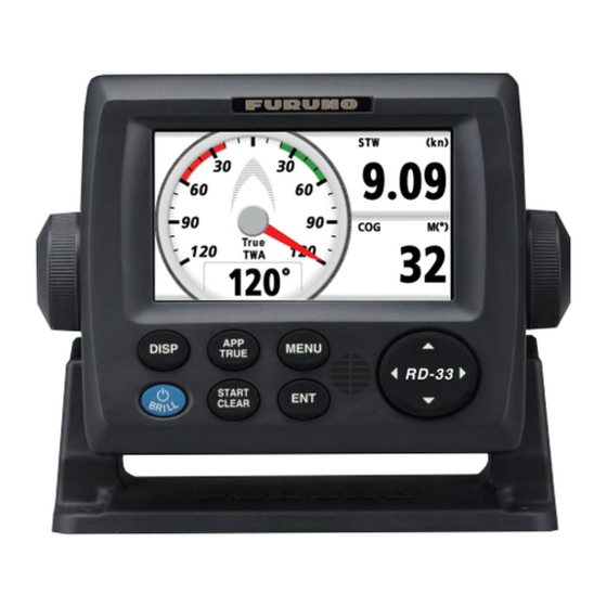
- Page 1 Back REMOTE DISPLAY RD-33 True www.furuno.com...
- Page 2 Nishinomiya, 662-8580, JAPAN A : JAN 2010 Printed in Japan All rights reserved. B : AUG . 04, 2011 Pub. No. OME-44590-B *00017318311* *00017318311* (AKMU ) RD-33 *00017318311* *00017318311* * 0 0 0 1 7 3 1 8 3 1 1 *...
-
Page 3: Important Notices
How to discard a used battery Some FURUNO products have a battery(ies). To see if your product has a battery(ies), see the chapter on Maintenance. Follow the instructions below if a battery(ies) is used. Tape the + and - terminals of battery before disposal to prevent fire, heat generation caused by short circuit. - Page 4 The voltage rating of the equipment appears on the label Failure to turn off the equipment above the power connector. can cause fire or electrical shock. Contact a FURUNO agent for CAUTION service. Keep heater away from the Ground the equipment to equipment.
-
Page 5: Table Of Contents
TABLE OF CONTENTS FOREWORD........................v SYSTEM CONFIGURATION ..................vi BASIC OPERATION....................1-1 1.1 Controls ........................1-1 1.2 How to Turn On/Off the Power ...................1-2 1.3 How to Adjust the Screen Brilliance/Key Dimmer............1-3 1.4 How to Step through the Data Screen................1-4 PROGRAMMED SCREEN..................2-1 2.1 How to Set the Analog Screen Appearance ...............2-1 2.2 How to Set the Programmed Screen................2-2 2.3 How to Customize the Factory-preset Screen............2-10... - Page 6 TABLE OF CONTENTS SYSTEM MENU .....................7-1 7.1 Units of Measurement ....................7-1 7.2 How to Set the Offset ....................7-2 7.3 Response Time ......................7-4 7.4 Scale Range....................... 7-4 7.5 Setting for Time and Date ..................7-5 7.6 Other menu items....................... 7-7 MAINTENANCE, TROUBLESHOOTING...............8-1 8.1 Maintenance.......................
-
Page 7: Foreword
• The design is consistent with NavNet 3D and FI-50, so there is uniformity in console installation. • Fulfill the conversion function between CAN bus and NMEA 0183, so the RD-33 is in relay be- tween existing equipments and CAN bus network. -
Page 8: System Configuration
CAN bus-compliant Device DISP MENU TRUE START NMEA 0183 Device CLEAR : Standard : Option RD-33 and NavNet 3D connection Up to three RD-33s can be connected on the CAN bus line. RD-33 NavNet 3D (Power supply) DISP MENU TRUE START... - Page 9 MENU DISP TRUE DISP MENU TRUE START START CLEAR CLEAR Junction Box FI-5002 12 VDC NMEA 0183, RD-33 and CAN bus device connection FI-50 series Instruments RD-33 NMEA 0183 NMEA 0183 Device DISP MENU TRUE (NavNet VX2 etc.) START CLEAR...
- Page 10 SYSTEM CONFIGURATION Environmental category RD-33 Protected from weather FI-5002 viii...
-
Page 11: Basic Operation
BASIC OPERATION Controls DISP MENU TRUE START CLEAR 3 4 5 6 Control Main description DISP Short press: Step through the seven data screens in the se- quence of Display1 → Display2 → Display3 → Display4 → Display5 → Display6 → Display7 → Display1 → ... Long press: Step through the screens in reverse order. -
Page 12: How To Turn On/Off The Power
Turn on the power Press the key to turn on the power. The start-up screen appears followed by the last-used data screen. RD-33 Booter(1) ver.XX.XX (build:YYYY/MM/DD) Program No: 2651011-XX.XX Initializing... Waiting for update request from SIO... Waiting for update request from CAN... -
Page 13: How To Adjust The Screen Brilliance/Key Dimmer
1. BASIC OPERATION Turn off the power Press and hold down the key until the screen turns off. The following count- down window appears until the power goes off. Turn Off in 3s. How to Adjust the Screen Brilliance/Key Dimmer You can adjust the screen brilliance and key dimmer as follows: 1. -
Page 14: How To Step Through The Data Screen
1. BASIC OPERATION How to Step through the Data Screen You can step through the seven data screens with the DISP key. When you press the DISP key momentarily, the screen changes in the sequence of Display1 → Display2 → Display3 → Display4 → Display5 → Display6 → Display7 → Display1 → ... The de- fault screens are as shown below. -
Page 15: Programmed Screen
PROGRAMMED SCREEN The RD-33 displays the data in three types; digital, analog and graph formats. Also, this equipment provides six programmed screen patterns which meets the purposes; [Fishing], [Sailing], [Ship], [Navigation], [Environment] and [Engine]. Availability of data depends on the sensors connected. -
Page 16: How To Set The Programmed Screen
5. Press the DISP key to close the menu and display the data screen. How to Set the Programmed Screen The RD-33 provides six programmed screens and each screen has four preset screens. You can select one of them as the data screen. - Page 17 2. PROGRAMMED SCREEN E.g. [Fishing] screen Note: For [Custom Layout], see the next chapter. 5. Use the Cursorpad to select the screen desired and press the ENT key. 6. Select the screen for [Display2] to [Display7] in the same method. Display options for [Display2] to [Display7] Note: If you selected [Off] on the [Display2] to [Display7], the data screen is skipped by pressing the DISP key.
- Page 18 2. PROGRAMMED SCREEN Programmed screen patterns Note: For explanation of abbreviations shown on the screen, see APPENDIX 2. Menu item Description Screen Fishing The screen for fishing. Pattern 1: SOG (Analog meter for Speed Over the Ground), Depth, W Temp (Water tempera- ture) Pattern 1 Pattern 2:...
- Page 19 2. PROGRAMMED SCREEN Menu item Description Screen Sailing The screen for sailing. Pattern 1: STW (Analog meter for Speed Through the Water), Depth, W Temp (Water tempera- ture) Pattern 1 Pattern 2: AWA (Analog meter for Ap- parent Wind Angle), AWS (Apparent Wind Speed), STW (Speed Through the...
- Page 20 2. PROGRAMMED SCREEN Menu item Description Screen Ship The screen for ship data. Pattern 1: Roll/Pitch (Analog meter for Roll and Pitch) Pattern 1 Pattern 2: ROT (Analog meter for Rate Of Turn), SOG (Speed Over the Ground), HDG (Heading) Pattern 2 Pattern 3: Rudder Angle (Analog...
- Page 21 2. PROGRAMMED SCREEN Menu item Description Screen Navigation The screen for navigation. Pattern 1: HDG (Heading meter) (Blue line: COG) Pattern 1 Pattern 2: BRG (Bearing), COG (Course Over the Ground), RNG (Range), SOG (Speed Over the Ground), Position (Latitude/Longi- tude), Pattern 2 XTE (Cross-track Error),...
- Page 22 2. PROGRAMMED SCREEN Menu item Description Screen Environment The screen for environ- ment. Pattern 1: W Temp (Water tempera- ture graph), APress (Air pressure), Air Temp (Air temperature) Pattern 1 Pattern 2: Air Temp/HUMID (Analog meter for air temperature and humidity), °...
- Page 23 2. PROGRAMMED SCREEN Menu item Description Screen Engine The screen for engine. Pattern 1: RPM (Analog meter for En- gine Revolutions Per Minute), SOG (Speed Over the Ground), COG (Course Over the Ground) Pattern 1 Pattern 2: RPM (Analog meter for En- gine Revolutions Per Minute), Boost (Analog meter for en-...
-
Page 24: How To Customize The Factory-Preset Screen
2. PROGRAMMED SCREEN How to Customize the Factory-preset Screen You can change the settings of the factory-preset data screen. How to change the display item 1. With the data screen displayed, press the ENT key. The screen changes as be- low. - Page 25 2. PROGRAMMED SCREEN 4. Use the Cursorpad ( ) to select the category and press the ENT key. The category options screen, which differs depending on the selected category, ap- pears. Category options (e.g. [Speed] category) Note 1: If you selected [None] in the category list, the data screen is blank. Note 2: For details of each category, see section 3.2.
- Page 26 2. PROGRAMMED SCREEN E.g. SOG properties window 4. Use the Cursorpad ( ) to select an option and press the ENT key. Options window Setting window Window examples 5. Use the Cursorpad ( ) to select an option or numeric value then press the ENT key.
-
Page 27: Custom Screen
CUSTOM SCREEN You can arrange the data to display and show the data in the order desired. Availability of data depends on the sensors connected. How to Customize the Screen 1. Press the MENU key to open the menu. 2. Use the Cursorpad ( ) to select [Display] and press the ENT key. - Page 28 3. CUSTOM SCREEN 5. Use the Cursorpad to select the screen division and press the ENT key. The op- tion screen depends on the selected screen division. Four-way spilit No-spilit Horizontal two-way spilit Examples of option screen 6. Press the ENT key again with the cursor on [A]. Scroll bar 7.
-
Page 29: Options For Categories
3. CUSTOM SCREEN 8. Use the Cursorpad ( ) to select an option desired and press the ENT key. Style options (e.g. [Speed] category) Note: The menu items in gray are not available. 9. Use the Cursorpad ( ) to select [Digital], [Analog] or [Graph] then press the ENT key. - Page 30 3. CUSTOM SCREEN Category Option Description Indication Wind Wind Speed Apparent Wind Speed (AWS): Wind AWS, speed measured by wind transduc- APP Wind SPD, TWS, True Wind Speed (TWS): Wind True Wind SPD speed calculated as if the ship is sta- tionary.
- Page 31 3. CUSTOM SCREEN Category Option Description Indication Navigation Bearing from your ship to the desti- nation waypoint Locked BRG Use for navigating with bearing for Locked BRG (See section the destination waypoint locked. 3.6.) Analog screen: The pointer indicates variation from the locked bearing. The digital shows the locked bearing or current bearing.
- Page 32 3. CUSTOM SCREEN Category Option Description Indication Environment Voltage Input voltage Volts, Voltage Time (See Current time Time section 7.5.) Date (See Current date Date section 7.5.) Water Temp Water temperature W Temp, Water Temp Air Temp Air temperature Air Temp Air Press Air pressure APress,...
-
Page 33: Data Screen
3. CUSTOM SCREEN Category Option Description Indication Fishery Current1 Current (tide) speed of first layer CUR 1, Current1 SPD Current1 Current (tide) direction of first layer CUR 1 DIR, Current1 DIR Current2 Current (tide) speed of second layer CUR 2, Current2 SPD Current2 Current (tide) direction of second... - Page 34 3. CUSTOM SCREEN Horizontal/vertical three-way split 2 Horizontal/vertical three-way split 1 Heading - ROT - Digital Engine - Engine RPM - Analog Fishery - Current1 SPD - Digital Speed - STW - Digital Fishery - Current1 DIR - Digital Wind - Wind Angle - Digital Horizontal/vertical three-way split 3 Auto Pilot - Rudder Angle - Analog Environment - Humidity - Digital...
-
Page 35: How To Switch The Wind Mode And The Direction Mode
3. CUSTOM SCREEN How to Switch the Wind Mode and the Direction Mode You can switch the wind mode and the direction mode as follows. Wind mode :Indication To switch the mode, press the APP/TRUE key. [APP]: Apparent or relative wind. The wind direction relative to the ship's bow and the wind speed relative to the moving ship. -
Page 36: Stopwatch And Timer
3. CUSTOM SCREEN 1. With the data screen displayed, press the ENT key. 2. Press the ENT key long. The properties screen, which depends on the selected data screen, appears. 3. Use the Cursorpad ( ) to select [Reference] and press the ENT key. 4. - Page 37 3. CUSTOM SCREEN Stopwatch To start the timer, press the START/CLEAR key. To lap or stop the timer, press the START/CLEAR key. Though the time indication stops, the count is continued internal- ly. To start the timer again, press the START/CLEAR key again. START/CLEAR [Stopwatch]: Count up timer Timer1 (2)
-
Page 38: Locked Hdg/Brg
3. CUSTOM SCREEN Locked HDG/BRG Analog screen Lock the heading or bearing at desired angle and display the variation from the locked heading or bearing in the analog meter. This function is available for no-split screen and horizontal/vertical three-way split 3 ( ) screen. - Page 39 3. CUSTOM SCREEN 3. Use the Cursorpad ( ) to select [Style] and use the Cursorpad ( ) to move the cursor to the right. 4. Press the ENT key. E.g. [Locked HDG] 5. Use the Cursorpad ( ) to select [Current Heading] or [Current Bearing] then press the ENT key.
-
Page 40: Cross-Track Error
3. CUSTOM SCREEN Cross-Track Error The cross-track error is displayed in the highway screen in analog format. The high- way screen provides a graphic presentation of ship’s progress toward a destination waypoint, with range and bearing to the destination waypoint, ship’s course and speed, and the ship’s position. -
Page 41: How To Switch The Digital Data For Heading And Wind Angle
3. CUSTOM SCREEN How to change the unit You can select the XTE unit from nm, km or sm as follows: 1. With the data screen for XTE displayed, press the ENT key. 2. Press the ENT key long. 3. Use the Cursorpad ( ) to select [Unit] and press the ENT key. -
Page 42: How To Reset The Value
3. CUSTOM SCREEN E.g. Magnetic heading Wind Angle (Available for Use the Cursorpad ( ) to switch the digital data for wind angle. The digital data chang- es as follows. The data changes in reverse order with the Cursorpad ( ). E.g. -
Page 43: Alarms
ALARMS Overview The RD-33 has 16 types of alarms as follows: • Arrival/Anchor • XTE • SOG • STW • Water Temperature • Depth • Time • Trip • Odometer • Roll • Pitch • Low Battery • Max True Wind Speed •... - Page 44 4. ALARMS 2. Use the Cursorpad ( ) to select [Messages] and press the ENT key. All alarms currently violated are displayed. 3. Press the DISP key to close the menu and display the data screen. Alarm category The alarm categories displayed on the alarm status are follows: Alarm category Meaning Reference...
- Page 45 4. ALARMS Alarm category Meaning Reference TIME ALARM! The preset time arrives. 4.3.8 TRIP ALARM! Your ship has traveled the trip distance set- ting or above. 4.3.6 ODOMETER ALARM! Your ship has traveled the odometer distance setting or above. ROLL ALARM! The right and left sway of your ship is equal to or exceeds the roll setting.
-
Page 46: Audio Alarm Type
4. ALARMS Audio Alarm Type You can select the audio alarm type as follows: 1. Open the [Alarms] menu. 2. Use the Cursorpad ( ) to select [Buzzer] and press the ENT key. 3. Use the Cursorpad ( ) to select [Short], [Long] or [Continuous] then press the ENT key. -
Page 47: Xte (Cross-Track Error) Alarm
4. ALARMS 4. Use the Cursorpad ( ) to move the cursor to the right and press the ENT key. 5. Use the Cursorpad to set the value and press the ENT key. The circle with radius setting value is alarm zone. : Change the figure. -
Page 48: Water Temperature Alarm
4. ALARMS 2. Use the Cursorpad ( ) to select [SOG] or [STW] then press the ENT key. 3. Use the Cursorpad ( ) to select [Low], [High], [Within] or [Outside] then press the ENT key. When you do not set the SOG/STW alarm, select [Off] and go to step 6. - Page 49 4. ALARMS 2. Use the Cursorpad ( ) to select [Water Temperature] and press the ENT key. 3. Use the Cursorpad ( ) to select [Low], [High], [Within], [Outside] or [Shear] then press the ENT key. When you do not set the water temperature alarm, select [Off] and go to step 6.
-
Page 50: Depth Alarm
4. ALARMS 4.3.5 Depth alarm The depth alarm alerts you when the depth is lower or higher than the depth setting, is inside or outside of the depth range setting, or is equal to the depth setting. 1. Open the [Alarms] menu. 2. -
Page 51: Roll/Pitch Alarm
4. ALARMS 2. Use the Cursorpad ( ) to select [Trip] or [Odometer] then press the ENT key. 3. Use the Cursorpad ( ) to select [On] and press the ENT key. When you do not set the trip/odometer alarm, select [Off] and go to step 6. 4. -
Page 52: Other Alarms
4. ALARMS 4.3.8 Other alarms The following are the other alarms. Menu item Description Remarks Time The time alarm alerts you Time data required. when the preset time ar- rives. Low Battery The low battery alarm alerts you when the input voltage is the voltage setting or be- low. -
Page 53: Input/Output Setup
INPUT/OUTPUT SETUP The RD-33 inputs and outputs the signal in NMEA 0183 and CAN bus format. CAN bus is the network system based on NMEA 2000. Received Data Status You can display all data input from the sensor. See the following table about the data. -
Page 54: Can Bus Devices Status
5. INPUT/OUTPUT SETUP CAN bus Devices Status You can display the status for up to 30 CAN bus devices connected. You can nick- name each device and these nicknames are used on the [Data Source] screen (see section 5.3). 1. Press the MENU key to open the menu. 2. -
Page 55: Data Source
5. INPUT/OUTPUT SETUP Data Source Set the data source and the PGN transmitting. How to select the data source You can select the data source to display on the screen when data of the same type is input from multiple sources. For example, you can select the position data from GPS navigation equipment or the position data from satellite compass when these two po- sition data are input. - Page 56 5. INPUT/OUTPUT SETUP 6. Press the DISP key to close the menu and display the data screen. Note: When the other units on CAN bus network is set to [On] for PGN transmit- ting, set [Off] in this RD-33.
-
Page 57: Position/Td Setup, Laylines
POSITION/TD SETUP, LAYLINES You can display the position of your ship in latitude and longitude or Loran C TDs. Also, you can display the laylines which is the indication of navigation at yacht sailing. Display Format for the Position of Your Ship Set the display format for the position of your ship. -
Page 58: Laylines
6. POSITION/TD SETUP, LAYLINES 5. If you selected [LC TD], do the following steps. 1) Use the Cursorpad ( ) to select [Loran C] and press the ENT key. Slave station pair GRI code 2) Use the Cursorpad ( ) to select the GRI (Group Repetition Interval) code desired and press the ENT key. - Page 59 6. POSITION/TD SETUP, LAYLINES 1. Press the MENU key to open the menu. 2. Use the Cursorpad ( ) to select [Laylines] and press the ENT key. 3. Use the Cursorpad ( ) to select [Upwind Angle Display] and press the ENT key.
- Page 60 6. POSITION/TD SETUP, LAYLINES 8. Use the Cursorpad ( ) to move the cursor to the right and press the ENT key. 9. Use the Cursorpad ( ) to set the time interval and press the ENT key. You can display the five past laylines per setting time interval. 10.
-
Page 61: System Menu
SYSTEM MENU This chapter describes the [System] menu. For [Demo Mode], [Self Test] and [Factory Reset], see chapter 8. Units of Measurement You can set the units of measurement for depth, ship speed, distance, wind speed, water temperature, fuel and engine pressure. 1. -
Page 62: How To Set The Offset
7. SYSTEM MENU 4. Use the Cursorpad ( ) to select [Depth], [Speed], [Distance], [Wind Speed], [Temperature], [Fuel] or [Engine Pressure] then press the ENT key. Depth Speed Distance Wind Speed Temperature Fuel Engine Pressure 5. Use the Cursorpad ( ) to select an option and press the ENT key. - Page 63 7. SYSTEM MENU 6. Use the Cursorpad ( ) to set the value and use the Cursorpad ( ) to move the cursor to the next digit. Repeat this step to set the value for other digits if nec- essary. When the displayed data is smaller than the actual value, set the plus val- ue.
-
Page 64: Response Time
7. SYSTEM MENU Response Time You can set the response time for each data as follows. The input raw data is aver- aged by the response time. 1. Press the MENU key to open the menu. 2. Use the Cursorpad ( ) to select [System] and press the ENT key. -
Page 65: Setting For Time And Date
7. SYSTEM MENU 3. Use the Cursorpad ( ) to select [Scale Ranges] and press the ENT key. 4. Use the Cursorpad ( ) to select the menu item desired and press the ENT key. 5. Use the Cursorpad ( ) to select an option and press the ENT key. - Page 66 7. SYSTEM MENU 3. Use the Cursorpad ( ) to select [Time Display] or [Date Display] then press the ENT key. Time Display Date Display 4. Use the Cursorpad ( ) to select an option and press the ENT key. 5.
-
Page 67: Other Menu Items
7. SYSTEM MENU Other menu items This section describes the menu items not previously described. [Key Beep]: When a key is pressed, a beep sounds. You can turn on or off this beep. [Language]: English and other languages are available. [HDG/COG Ref]: You can display the bearing in true or magnetic. - Page 68 7. SYSTEM MENU This page is intentionally left blank.
-
Page 69: Maintenance, Troubleshooting
MAINTENANCE, TROUBLESHOOTING NOTICE Do not apply paint, anti-corrosive sealant or contact spray to plastic parts or equipment coating. Those items contain products that can damage plastic parts and equipment coating. Maintenance Check the following points regularly to maintain performance: • Check that connections on the rear panel are firmly tightened and free of dust. •... -
Page 70: Troubleshooting
8. MAINTENANCE, TROUBLESHOOTING Troubleshooting This section provides simple troubleshooting procedures which the user can follow to restore normal operation. If you cannot restore normal operation, do not check inside the unit. Have a qualified technician check the equipment. Symptom Remedy You cannot turn on the power. - Page 71 8. MAINTENANCE, TROUBLESHOOTING System Test items Items Description ROM, RAM The results of the ROM/RAM test are displayed as "OK" or "NG" (No Good). If any NG is dis- played, contact your dealer. 0183 The result of the port NMEA 0183 is displayed as "OK"...
-
Page 72: Factory Reset
Demo Mode A demo mode, which shows internally generated navigation data, is provided to ac- quaint you with the features of the RD-33. "SIM" (simulation) appears on the screen when the demo mode is turned on. 1. Press the MENU key to open the menu. -
Page 73: Installation
INSTALLATION Equipment List Standard supply Name Type Code No. Remarks Remote Display RD-33 Installation CP20-03300 • CP20-03310* Materials • M12-05BM+05BF-060 Accessories FP20-01200* 001-087-250 *: See page A-1. Optional supply Name Type Code No. Remarks Junction Box FI-5002 Cable Assy. FI-50-CHAIN-0.3M 000-166-949-11 CAN bus, w/0.3 m cable, con-... -
Page 74: Installation
9. INSTALLATION Installation Mounting considerations The remote display can be installed on a desktop, on the underside of a table, or flush mounted in a panel. When you select a mounting location, remember the following points: • The nominal viewing distance for the display unit is 0.6 m. Select a suitable mount- ing location considering that distance. - Page 75 9. INSTALLATION 5. Attach the F mount cushion (supplied as accessories) to the remote display from the rear side. 6. Connect the cable connectors (see section 9.3). 7. Set the remote display to the cutout and fasten it with four self-tapping screws (supplied as installation material;...
-
Page 76: Wiring
NMEA 0183 device without the CAN bus device, con- nect the 12-24 VDC power from the ship’s switch board to the male connector of the CAN bus port. Interconnection RD-33 (rear) For CAN bus For CAN bus For CAN bus... - Page 77 9. INSTALLATION Connection between remote display and junction box For serviceman: See “Furuno CAN bus Network Design Guide” (TIE-00170-X) for de- tails about CAN bus network. RD-33 (rear) M12-05BM+05BF-0xx (1 m, 2 m, 6 m) Connect to CN2 - CN5.
- Page 78 DISP MENU TRUE START CLEAR Terminator Terminator Furuno CAN bus terminators are available with the following part numbers. The ter- minator should be attached at each end of the backbone cable. Parts name Type Code Number Remarks Male terminator LTWMN-05AMMT-...
-
Page 79: Adjustments
9. INSTALLATION Adjustments After you install the remote display, initialize the remote display as follows: 1. Press the key to turn on the power. 2. Press the ENT key with the cursor on [English]. The menu for units of measure- ment appears. -
Page 80: Input/Output Signal
9. INSTALLATION Input/Output Signal The RD-33 inputs and outputs the signal in NMEA 0183 and CAN bus format. Input signal Data Port Sentence, PGN (Title) Depth CAN bus 128267 (Water depth) NMEA 0183 DPT>DBT>DBS>DBK CAN bus 128259 (Speed, Water referenced),... - Page 81 9. INSTALLATION Data Port Sentence, PGN (Title) WP Name CAN bus 129285 (Navigation-Route/WP infor- mation NMEA 0183 RMB>APB>BWC>BWR>ZTG Longitude/Latitude CAN bus 129029 (GNSS Position data), 129025 (Position, Rapid Update) NMEA 0183 GNS > GGA > RMC > RMA > GLL Longitude/Latitude for way- CAN bus 129284 (Navigation data)
- Page 82 9. INSTALLATION Output signal Data Port Sentence, PGN (Title) Depth CAN→0183 128267→DPT 0183→CAN DPT>DBT>DBS>DBK→128267 CAN→0183 128259, 130577→VHW (Speed Through the Water) 0183→CAN VHW→128259 CAN→0183 128259, 130577→VTG, RMC (Speed Over the Ground) 0183→CAN VTG>RMC>RMA→128259, 129029 Wind speed and angle CAN→0183 130306→MWV(A) (Apparent)*1 0183→CAN MWV(A)>VWR→130306...
- Page 83 9. INSTALLATION Data Port Sentence, PGN (Title) Number of acquired satel- CAN→0183 lites 0183→CAN GNS>GGA→129029 Pitch/Roll CAN→0183 0183→CAN ETA Time&Date CAN→0183 0183→CAN Time difference CAN→0183 0183→CAN Date CAN→0183 126992, 129033→RMC 0183→CAN ZDA>RMC→126992 Time CAN→0183 126992, 129033→RMC 0183→CAN ZDA>RMC→126992 Water temperature CAN→0183 130310, 130311→MTW 0183→CAN...
- Page 84 9. INSTALLATION This page is intentionally left blank. 9-12...
-
Page 85: Appendix 1 Menu Tree
APPENDIX 1 MENU TREE MENU key Bold: Default setting Display Graphic (A, B) Display1 (Fishing, Sailing, Ship, Navigation, Environment, Engine, Custom Layout) Display2 (Fishing, Sailing, Ship, Navigation, Environment, Engine, Custom Layout, Off) Display3 (Fishing, Sailing, Ship, Navigation, Environment, Engine, Custom Layout, Off) Display4 (Fishing, Sailing, Ship, Navigation, Environment, Engine, Custom Layout, Off) Display5 (Fishing, Sailing, Ship, Navigation, Environment, Engine, Custom Layout, Off) Display6 (Fishing, Sailing, Ship, Navigation, Environment, Engine, Custom Layout, Off) - Page 86 APPENDIX 1 MENU TREE (Continued from previous page) Pos/TD Display (xx.xxx’ , xx’ xx.x’’ , LC TD) Setup Loran C (List of Loran-C chains and pairs of slave stations) TD1 (Offset: -99.9 - +99.9; +0.0) TD2 (Offset: -99.9 - +99.9; +0.0) °...
- Page 87 APPENDIX 1 MENU TREE (Continued from previous page) Speed (0-20kn, 0-40kn, 0-80kn) Scale Ranges Volts (8-16V, 16-32V) Engine Speed RPM (0-4x1000RPM, 0-6x1000RPM, 0-8x1000RPM) Engine Boost Pressure (0-30psi, 0-70psi, 0-150psi, 0-360psi, 0-440psi) ° ° Engine Temperature (150-250 F, 120-300 Engine Oil Pressure (0-30psi, 0-70psi, 0-150psi, 0-360psi, 0-440psi) °...
-
Page 88: Appendix 2 List Of Terms
APPENDIX 2 LIST OF TERMS The following table shows the terms used in the RD-33. Term Meaning A(ir) Press Air Pressure Air Temp Air Temperature Apparent: Aapparent or relative wind. The wind direction relative to the ship’s bow and the wind speed relative to the moving vessel. - Page 89 APPENDIX 2 LIST OF TERMS Term Meaning Oil P Oil Pressure Port POSN Position Pound per square inch Range Rate Of Turn Revolutions Per Minute Starboard second(s) Satellite Speed Over the Ground Speed Speed Through the Water STWAVG Speed Through the Water Average STWMAX Speed Through the Water Maximum True: True wind.
-
Page 90: Specifications
FURUNO RD-33 SPECIFICATIONS OF REMOTE DISPLAY RD-33 GENERAL Display type 4.3-inch color LCD, 480 x 272 dots (WQVGA) Picture color 256 colors Display mode Data, Graph, Graphic Data indication Ship’s speed, Course, Heading, Trip, Depth, Wind direction/speed, Navigate information, Environmental information, Rudder angle, Engine’s information... -
Page 95: Index
INDEX Adjustments ..........9-7 Magnetic variation ........7-7 Alarm category .......... 4-2 Maintenance..........8-1 Alarm menu..........4-3 Menu tree ..........AP-1 Alarm status ..........4-1 Analog screen appearance ....... 2-1 Odometer alarm ........4-8 Anchor alarm..........4-4 Offset............7-2 Arrival alarm ..........4-4 Other alarms ...........
Need help?
Do you have a question about the RD-33 and is the answer not in the manual?
Questions and answers