Table of Contents
Advertisement
Quick Links
Advertisement
Table of Contents

Related Manuals for Furuno BBDS1


Summary of Contents for Furuno BBDS1
- Page 1 OPERATOR'S MANUAL Bottom Discrimination Sounder BBDS1 Model www.furuno.com...
- Page 3 How to discard a used battery Some FURUNO products have a battery(ies). To see if your product has a battery, see the chapter on Maintenance. If a battery is used, tape the + and - terminals of the battery before disposal to pre- vent fire, heat generation caused by short circuit.
- Page 4 Turn off the power immediately if you Do not remove the label. If a label is missing feel the equipment is acting abnormally. or illegible, contact a FURUNO agent or dealer about replacement. If the equipment is very warm or is...
- Page 5 SAFETY INSTRUCTIONS Safety instructions for the installer WARNING CAUTION CAUTION The transducer cable must be handled Do not open the equipment. carefully, following the guidelines below. Only qualified personnel should work inside the equipment. Keep fuels and oils away from the ●...
-
Page 6: Table Of Contents
TABLE OF CONTENTS FOREWORD ........................v SYSTEM CONFIGURATION ..................vi EQUIPMENT LIST ......................vii MOUNTING .......................1 1.1 Bottom Discrimination Sounder..................1 1.2 Transducer 520-5PSD, 520-5MSD ................2 1.2.1 Mounting location....................2 1.2.2 Acceptable mounting locations ................3 1.2.3 Installation Procedure .................... 4 1.3 Transducer 525-5PWD (transom mount) ..............5 1.3.1 Installation for flat hulls .................. -
Page 7: Foreword
Operational cautions: Please keep the following in mind when using the Bottom Discrimination Sounder: • The BBDS1 is for use with NavNet 3D (MFD8/12/BB), NavNet TZtouch (TZT9/14/BB) and NavNet TZtouch2 (TZTL12F/15F, TZT2BB). • Use at a depth of 5 m - 100 m. -
Page 8: System Configuration
SYSTEM CONFIGURATION Bottom Discrimination Sounder BBSD1 NavNet Equipment MFD8/12/BB TZT9/14/BB TZTL12F/15F, TZT2BB NavNet Equipment HUB-101 NavNet Equipment Matching Box MB-1100 Rectifier PR-62 12-24 VDC 100/110/220/230 VAC, Speed/temperature Transducer Transducer 1ø, 50/60 Hz sensor 520-5PSD 50/200-1T ST-02MSB 525-5PWD ST-02PSB 520-5MSD Temperature Triducer sensor 525STID-MSD... -
Page 9: Equipment List
EQUIPMENT LIST Standard supply Name Type Code No. Remarks Bottom Discrimination Sounder BBDS1 Spare Parts SP02-05201 001-007-860 1 set Fuse Installation Materials CP02-08700 000-017-040 1 set See Packing List Optional supply Name Type Code No. Remarks Matching Box MB-1100 000-041-353... -
Page 10: Mounting
MOUNTING Bottom Discrimination Sounder CAUTION CAUTION Do not apply paint, rust protection, etc, to coated surface parts of the unit. These may damage the coated surface areas. Be especially careful not to apply chemicals to the coated connectors. The Bottom Discrimination Sounder can be installed on a desktop, deck or on a bulkhead. When selecting a mounting location for the Bottom Discrimination Sounder, keep the following in mind: •... -
Page 11: Transducer 520-5Psd, 520-5Msd
1. MOUNTING Transducer 520-5PSD, 520-5MSD 1.2.1 Mounting location The performance of this sounder is directly related to the mounting location of the transducer, es- pecially for high-speed cruising. The installation should be planned in advance, keeping the stan- dard cable length and the following factors in mind: •... -
Page 12: Acceptable Mounting Locations
1. MOUNTING 1.2.2 Acceptable mounting locations Deep V-hull * Position 1/2 to 1/3 length of the hull from stern. * 15-30 cm from keel line (inside first lifting strakes). High speed V-planning hull * Within the submerged bottom area * Deadrise angle within 15°... -
Page 13: Installation Procedure
1. MOUNTING 1.2.3 Installation Procedure 1. With the boat hauled out of the water, mark the location selected for mounting the transducer on the bottom of the hull. If the hull is not level within 15 degrees in any direction, fairing blocks made out of teak should be used between the transducer and hull, both inside and outside, to keep the transducer face parallel with the water line. -
Page 14: Transducer 525-5Pwd (Transom Mount)
1. MOUNTING Transducer 525-5PWD (transom mount) This type of mounting is very commonly employed for outboard motor boats. Do not use this meth- od on an inboard motor boat because turbulence is created by the propeller ahead of the trans- ducer. -
Page 15: Installation For Deep-V Hulls
1. MOUNTING 1.3.2 Installation for deep-V hulls This method is employed on deep-V hulls and provides good performance because the effects of air bubbles are minimal. Install the transducer parallel with water surface; not flush with hull. If the boat is placed on a trailer care must be taken not to damage the transducer when the boat is hauled out of the water and put on the trailer. -
Page 16: Optional Water Temperature Sensor St-02Msb, St-02Psb
1. MOUNTING Optional Water Temperature Sensor ST-02MSB, ST-02PSB Select a suitable mounting location considering the following points: • Select a mid-boat flat position. The sensor does not have to be installed perfectly perpendicular. The sensor must not be damaged in dry-docking operation. •... -
Page 17: Optional Triducers
1. MOUNTING Optional Triducers 1.5.1 Thru-hull triducer 525STID-MSD See section 1.4 for how to install the 525STID-MSD. 133 mm 79 mm (5.2”) Height to the screw (3.1”) Thread 7mm (0.3”) 51 mm (2.0”) 27 mm 140 mm (1.1”) (5.5”) 525T-BSD/526TID-HDD For details of the installation, see the manual of the triducer. - Page 18 1. MOUNTING Mounting location To ensure the best performance, the sensor must be submerged in aeration-free and turbulence- free water. Mount the sensor close to the centerline of the boat. On slower heavier displacement hulls, positioning it farther from the centerline is acceptable. Allow adequate space above the bracket for it to release and rotate the sensor upward.
- Page 19 1. MOUNTING 3. Using a 4 mm, #23, or 9/64" bit, drill three holes 22 mm (0.9”") deep at the locations indicated. To prevent drilling too deeply, wrap masking tape around the bit 22 mm (0.9") from the point. Fiberglass hull: Minimize surface cracking by chamfering the gelcoat. If a chamfer bit or coun- tersink bit is not available, start drilling with a 6mm or 1/4"...
- Page 20 1. MOUNTING 2°-10° transom angle (stepped transom and jet boats): Position the shim with the tapered end down. 19°-22° transom angle (small aluminum and fiberglass boats): Position the shim with the ta- pered end up. 2°-10° 19°-22° 11°transom transom angle transom angle angle Shim with...
- Page 21 1. MOUNTING Cable routing Route the sensor cable over the transom, through a drain hole, or through a new hole drilled in the transom above the waterline. Never cut the cable or remote the connector; this will void the warranty. Always wear safety gog- gles and a dust mask.
-
Page 22: Wiring
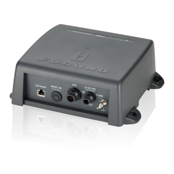
WIRING Connections Connect the NavNet equipment, power cable and transducer cable as shown in the figure below. BBDS1 12-24 VDC 1.1-0.4 A 3 GND MODE SW 1 2 3 4 NETWORK MOD-Z072-50+ cable, 5m (2/10m, option) HUB-101 GROUND WIRE MOD-WPAS0001-030+ cable, 3m IV-1.25sq... -
Page 23: Optional Temperature/Speed Sensor, Temperature Sensor
NC (Temp. sensor) 12V (Temp./speed sensor) +12V NC (Temp. sensor) TD_ID_XDR MJ-A10SRMD XDR_P XDR_SHIELD XDR_M Transducer XDR port on the BBDS1 XDR_P XDR_SHIELD XDR_M Connect to XDR port at Bottom Discrimination Sounder MJ-A10SPF MJ-A6SRMD MJ-A10SRMD Tape connectors with vulcanizing tape and then vinyl tape to waterproof them. -
Page 24: Wiring Optional 1 Kw Transducer
J2: Full power output J1: Reduced power output 02P6348 50/200-1T SHIELD Connect the 10P connector to the XDR port of the bottom discrimination sounder BBDS1. GRN (SHIELD) Matching Box: Type MB-1100, Code Number 000-041-353 Name Type Code no. Remarks Matching Box MB-1100... -
Page 25: Initial Settings, Operation
NavNet network other than the NavNet 3D network, turn the 1st unit OFF and the 2nd unit ON. • BBDS1, 2 units • DFF1, 2 units • BBDS1, 1 unit, DFF1, 1 unit (total of 2 units) Factory testing OFF: Testing OFF ON: Testing ON (Default: OFF) -
Page 26: Operation Check (Led)
3. INITIAL SETTINGS, OPERATION Operation Check (LED) The BBDS1 is powered on and off according to the NavNet series it is connected to: NavNet TZtouch/TZtouch2: Powered on and off from the mains switchboard. NavNet 3D: Powered on and off from a display unit. -
Page 27: Maintenance
Use of a wrong fuse can result in damage to the equipment or cause fire. blown. Find out the cause for blown fuse before re- placing a fuse. If a fuse blows again after replace- ment, contact a FURUNO agent or dealer for advice. -
Page 28: Appendix 1 Installation Of Temperature Sensors
APPENDIX 1 INSTALLATION OF TEMPERATURE SENSORS The installation instructions in this chapter are copied from the manufacturer's (AIRMAR Technology Corporation) installation guide, which is included with your sensor. The model numbers mentioned within the documentation should be read as follows: T42 =>... - Page 29 APPENDIX 1 INSTALLATION OF TEMPERATURE SENSORS AP-2...
- Page 30 APPENDIX 1 INSTALLATION OF TEMPERATURE SENSORS AP-3...
- Page 31 APPENDIX 1 INSTALLATION OF TEMPERATURE SENSORS AP-4...
- Page 32 APPENDIX 1 INSTALLATION OF TEMPERATURE SENSORS AP-5...
-
Page 33: Specifications
FURUNO BBDS1 SPECIFICATIONS OF BOTTOM DISCRIMINATION SOUNDER BBDS1 GENERAL Output power 600 W/ 1 kW rms nominal, 1 kW requires optional MB-1100 TX frequency 50 kHz or 200 kHz, 50/200 kHz alternating Amplifier type Wide dynamic linear amp (double superheterodyne) - Page 37 When a claim is made, FURUNO has a right to choose whether with other electronic devices. The imported product may also be to repair the product or replace it.
- Page 38 24 months from installation date provided the work is done by Furuno U.S.A., Inc. or an AUTHORIZED Furuno dealer during normal shop hours and within a radius of 50 miles of the shop location.
- Page 39 (title and/or number and date of issue of the standard(s) or other normative document(s)) For assessment, see • EMC Test Report FLI 12-10-023, June 22, 2010 prepared by Furuno Labotech International Co., Ltd. This declaration is issued according to the Directive 2014/30/EU of the European Parliament and of the Council of 26 February 2014 on the harmonisation of the laws of the Member States relating to electromagnetic compatibility.
- Page 40 (Elemental Chlorine Free) The paper used in this manual is elemental chlorine free. FURUNO Authorized Distributor/Dealer 9-52, Ashihara-cho, Nishinomiya, 662-8580, JAPAN A: JUL. 2010 All rights reserved. Printed in Japan K1: DEC. 17, 2019 Pub. No. OME-20380-K1 (ETMI) BBDS1 00017339119...
Need help?
Do you have a question about the BBDS1 and is the answer not in the manual?
Questions and answers