Table of Contents
Advertisement
Advertisement
Table of Contents
Troubleshooting

Subscribe to Our Youtube Channel
Related Manuals for Furuno FCV-668


Summary of Contents for Furuno FCV-668
- Page 3 Use of a wrong fuse can result in damage the equipment. to the equipment. Continued use of the equipment can cause fire or electrical shock. Contact a FURUNO agent for service. CAUTION Do not disassemble or modify the equipment.
-
Page 4: Table Of Contents
TABLE OF CONTENTS 2.14 Selecting Background and TABLE OF CONTENTS ........ii Echo Colors ........2-14 INTRODUCTION ..........iii 2.15 Alarms ..........2-14 PRINCIPLE OF OPERATION ......v 2.16 White Marker ........2-16 SYSTEM CONFIGURATION ......vi 2.17 Demonstration Picture....... 2-16 1. -
Page 5: Introduction
This dedication to excellence is furthered by our extensive global network of agents and dealers. The FCV-668 is just one of the many FURUNO developments in the field of echo sounding. The compact, lightweight but rugged unit is easy to install and operate and is suitable for both fresh and saltwater applications. - Page 6 • Alarms: fish, bottom, water temperature (requires appropriate sensor). • Six pulselengths for excellent performance on both shallow and deep ranges. • Universal 12-24 VDC power supply drawing 30 W of power at maximum. • Water temperature/speed sensor optionally available.
-
Page 7: Principle Of Operation
PRINCIPLE OF OPERATION This Color Video Sounder determines the distance between its transducer and underwater objects such as fish, lake bottom or seabed and displays the results on a 6-inch color screen. It does this by utilizing the fact that an ultrasonic wave transmitted through water travels at a nearly constant speed of 4800 feet (1500 meters) per second. -
Page 8: System Configuration
SYSTEM CONFIGURATION DISPLAY UNIT CV-668 Ship's mains 12-24 VDC TRANSDUCER External equipment Standard supply (GPS navigator, etc.) 520-5PSC-A SPEED, TEMPERATURE SENSOR (option) Optional supply Speed/temperature sensor 520-5PWC ST-02MSB 520-5MSC-A ST-02PSB 520ST-PWA ST-01PTB 524ST-MSA Temperature sensor T-02MTB T-02MSB T-03MSB... -
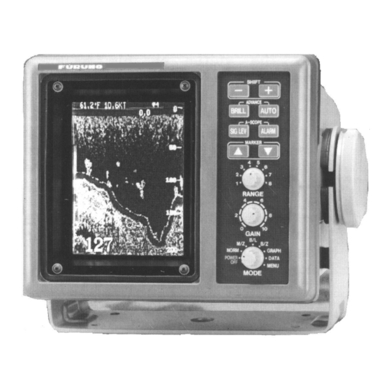
Page 9: Controls, Indications
1. CONTROLS, INDICATIONS Control Description The equipment is so designed that even a first time user can quickly become acquainted with the operating procedure. Operation of each control or key is acknowledged by an alphanumeric message or symbol indication on the screen. Control Function •... -
Page 10: Indications
Indications Speed* Noise Limiter Picture Advance Speed Signal Level Alarm Type (F,B,TI,TB) ç Active alarm Water 49.8˚F 12.5kt 1 SL1 temperature* Minute marker 35°15.000' N (yellow, blue, Nav data* 135°07.500' W 30 sec. each) Water temperature scale* Range scale Alarm zone marker Water temperature marker* (Color... -
Page 11: Basic Operation
2. BASIC OPERATION Turning the Power On/Off Turn the [MODE] switch clockwise to turn the power on. The unit starts with the settings used before it was turned off last time. Note that there is a few seconds delay prior to display of the picture until the CRT warms up. - Page 12 2.3.2 Display mode description NORM display The normal display appears on the full screen. This mode is useful for general observation of the seabed and fish schools. Fish school Bottom 49.6 M/Z (Marker Zoom) mode The marker zoom mode expands selected area of the normal picture to full vertical size Normal display...
- Page 13 B/L (Bottom-Lock) mode Zoom marker (yellow) The bottom-lock mode shows a compressed normal T h i s s e c t i o n picture on the top 2/3 of the screen and a 5 or 10 meter i s z o o m e d (10 or 20 feet) wide layer in contact with the bottom is expanded onto the bottom 1/3 of the screen.
- Page 14 GRAPHIC mode The graphic mode presents navigation data (speed, position, course, depth, water temperature, waypoint data, and cross-track error) in analog form. Trip Distance* TRIP NM 123.0 Speedometer* Speed* SPEED 10.6 Depth Alarm Range DEPTH : 19 TEMP Water Temperature* 84.7˚F Waypoint* WPT: FOX1...
- Page 15 Enlarging a nav data indication You can enlarge and display one of the data indications as follows. 5. Press [ ] or [ ] to select the indication you want to enlarge. A blue cursor circumscribes your selection. For example, select the depth indication. 6.
-
Page 16: Adjusting Gain
Adjusting Gain The [GAIN] control adjusts the sensitivity of the receiver. Adjust it so that a slight amount of noise remains on the screen. Generally, use a higher gain setting for greater depths and a lower setting for shallower waters. Gain too high Gain proper Gain too low... -
Page 17: Selecting Picture Advance Speed
Selecting Picture Advance Speed The picture advance speed determines how quickly the vertical scan lines run across the screen. When selecting a picture advance speed, keep in mind that a fast advance speed will expand the size of the fish school horizontally on the screen and a slow advance speed will contract it. 1. -
Page 18: Erasing Weak Echoes
Operate the [RANGE] switch and the display shown below appears. Adjust the [RANGE] control again to select a basic range. RANGE: 30 ft Note: The [RANGE] switch is inoperative when the auto functions is active. 2.7.2 Range shifting The basic range may be shifted up or down with the [SHIFT] keys ([+], [-]). Press a [SHIFT] key and the display shown below appears. -
Page 19: Measuring Depth To A Fish School
Measuring Depth to a Fish School The VRM (Variable Range Marker) functions to measure the depth to fish schools or other echo. 1. Press [ ] or [ ] to place the VRM on an echo. 2. Read the VRM range just above the VRM. VRM (green) 39.8 49.6... -
Page 20: Menu Operation
2.11 Menu Operation The menu, consisting of the main menu and three system menus, contains less often used functions which do not require frequent adjustment. 2.11.2 Menu selection 1. Set the [MODE] switch in the MENU position. NOISE LIMITER 1 2 3 HUE SELECTION (1 - 7) GAIN ADJUST 50KHZ*... - Page 21 3. You can switch among system menus by selecting MENU and using [+] or [-]. ( * SYSTEM MENU [1] *) (* SYSTEM MENU [2] *) (* SYSTEM MENU [3] *) MENU : [1] [2] [3] MENU : [1] [2] [3] MENU : [1] [2] [3] DEPTH :...
- Page 22 Selects digital data to display at top-left corner on the screen. L/L, latitude and longitude position; R/B, Range and bearing to waypoint, CSE, Ship's course. FORMAT Selects format of data fed from nav sensor. CIF (FURUNO developed) is standard data format of FURUNO equipment. SPD SEL Selects source of speed data.
-
Page 23: Suppressing Interference
2.12 Suppressing Interference Interference from other acoustic equipment operating nearby or other electronic equipment on your boat may show itself on the display as shown below. To suppress interference, do the following: 1. Select MENU with the [MODE] switch. 2. Select NOISE LIMITER. 3. -
Page 24: Selecting Background And Echo Colors
2.14 Selecting Background and Echo Colors 1. Select MENU with the [MODE] switch. 2. Press [ ] to select HUE SELECTION. 3. Press [+] or [-] to select hue arrangement desired, referring to the table below. Hue options Hue No. Background color Echo color Blue... - Page 25 2.15.2 Activating an alarm 1. Press the [ALARM] key to display the alarm menu. BOTTOM ALARM ZONE : 0 --- RANGE : FISH ALARM ZONE : 0 --- RANGE : TEMP OFF IN OUT ALARM ZONE : 32 --- 37 RANGE : : TO SELECT ITEM.
-
Page 26: White Marker
2.16 White Marker The white marker functions to display a particular echo color in white. For example, you may want to display the bottom echo (reddish-brown) in white to discriminate fish echoes near the bottom. Note that the bottom must be displayed in reddish-brown for the white marker to function. -
Page 27: Correcting Speed/Water Temperature Readout
2.18 Correcting Speed/Water Temperature Readout Wrong ship's speed or water temperature indication can be corrected on the system menu 2 as follows: 1. Set the [MODE] switch in the MENU position. 2. Press [ ] until GO TO SYSTEM MENU appears and then press [+] to select YES. 3. -
Page 28: Interpreting The Display
3. INTERPRETING THE DISPLAY Zero Line Zero The zero line (sometimes referred to as the transmission line) line represents the transducer's position, and moves off the screen when a deep phased range is used. Fish School Echoes Shift Fish school echoes will generally be plotted between the zero line and the bottom. -
Page 29: Surface Noise/Aeration
Surface Noise/Aeration When the waters are rough or the boat passes over a wake, surface noise may appear near the zero line. As surface turbulence is acoustically equivalent to running into a brick wall, the bottom echo will be displayed intermittently. Similar noise sometimes appears when a water temperature difference (thermocline) exists. -
Page 30: Maintenance, Troubleshooting
4. MAINTENANCE, TROUBLESHOOTING WARNING ELECTRICAL SHOCK HAZARD Do not open the equipment. Only qualified personnel should work inside the equipment. Maintenance Regular maintenance is important for good performance. Following the recommended maintenance procedures will help keep your set in good working condition. 4.1.2 General checking Important points to be checked from time to time are tabulated below. - Page 31 4.1.4 Cleaning Keep the equipment clean and dry at all times. Dust or loose dirt should be wiped off with a soft, dry cloth. Do not use chemical cleaners to clean the display unit - they can remove paint or markings.
-
Page 32: Basic Troubleshooting
Basic Troubleshooting The troubleshooting table below presents common problems and the means to restore normal operation. If normal operation cannot be restored do not attempt to check inside the equipment. Basic troubleshooting If… Then check battery voltage. • neither echo nor fixed range scale appears •... -
Page 33: Diagnostics
# 200 kHz depending on transducer used. Note: If NG apepars instead of OK for any device or panel switch, contact FURUNO for service. Do not attempt to check inside the unit because of the high voltage used in the equipment. -
Page 34: Transducer Check
Transducer Check A simple and reliable check of the transducer is to temporarily replace the transducer with a new one. If the sensitivity is considerably improved through this change, the transducer is probably faulty. This method is especially useful for inside-hull or through-hull installation. Another method is to listen to the transmission sound. -
Page 35: Menu Tree
MENU TREE NOISE LIMITER PRess [+] at NL1 NL2 NL3 [MODE] switch in GO TO SYSTEM MENU position HUE SELECTION MENU. (1 - 7) ( * SYSTEM MENU [1] *) * 200 kHz depending on GAIN ADJUST 50KHZ* transducer used. MENU : [1] [2] [3] (-20 - +20) -
Page 36: Specifications
SPECIFICATIONS OF COLOR VIDEO SOUNDER FCV-668 1. GENERAL (1) Display 6-inch diagonal CRT (2) Echo Color 8 colors (including background color) according to echo intensity. Monochrome display is also available. The background color is selectable from blue, light blue, white and black. - Page 37 *: Speed/temperature sensor required. 2. POWER SUPPLY (1) Display Unit 12-24 VDC (-10%, +30%): 2.5-1.25 A 3. ENVIRONMENTAL CONDITION (1) Ambient Temperature 0°C to +50°C (2) Relative Humidity 85% at 40°C (3) Water proofing Display Unit: IPX4 (4) Vibration ±1 mm ±10%, 2(5) to 13.2 Hz, Maximum acceleration 7 m/s , 13.2 to 100 Hz 4.
-
Page 38: Index
INDEX Aeration............3-2 Indications.............1-2 Alarms Interference..........2-13 activating ..........2-15 Main menu ..........2-10 bottom ............ 2-14 Marker zoom mode ........2-2 fish ............2-14 Menu silencing buzzer........2-15 main menu description ......2-11 water temperature........2-14 menu selection ........2-10 A-scope display ..........2-9 system menu description ......2-12 AUTO key.............
Need help?
Do you have a question about the FCV-668 and is the answer not in the manual?
Questions and answers