Table of Contents
Advertisement
Quick Links
WARNING: If the information in this manual is not followed exactly, a fire or explosion may result causing
property damage, personal injury, or loss of life.
For your safety
Do not store or use gasoline or other flammable vapors and liquids in the vicinity of this or any other appliance.
What to do if you smell gas
Do not try to light any appliance.
Do not touch any electrical switch; do not use any phone in your building.
Immediately call your gas supplier from a neighbor's phone. Follow the gas supplier's instructions.
If you cannot reach your gas supplier, call the fire department.
Installation and service must be performed by a qualified installer, service agency or the gas supplier.
Please read this manual before installing or using this appliance. Retain this manual for future reference.
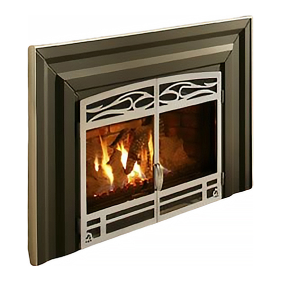
SATURNA
Natural Gas & Propane
Direct Vent Gas Fireplace Insert
Installation and Operating Instructions
Advertisement
Table of Contents

Related Manuals for Osburn SATURNA


Summary of Contents for Osburn SATURNA
- Page 1 SATURNA Natural Gas & Propane Direct Vent Gas Fireplace Insert Installation and Operating Instructions WARNING: If the information in this manual is not followed exactly, a fire or explosion may result causing property damage, personal injury, or loss of life.
-
Page 2: Table Of Contents
LEANING OF GOLD PLATED SURFACES ..................32 4.5 B & URNER PILOT CLEANING ....................... 32 4.6 F & ................32 AN REPLACEMENT ELECTRICAL SCHEMATIC 5.0 TROUBLE SHOOTING ......................34 6.0 REPLACEMENT PARTS ......................36 OSBURN LIMITED LIFETIME WARRANTY ..............37... -
Page 3: Introduction
1.0 INTRODUCTION 1.1 Specifications TABLE 1 ITEM NATURAL GAS (NG) PROPANE (LPG) INPUT: Hi 35,000 Btu/hr (10.25kW) 35,000 Btu/hr (10.25kW) INPUT: Lo 17,500 Btu/hr (5.13kW) 17,500 Btu/hr (5.13kW) MANIFOLD PRESSURE: Hi 3.5” w.c. (0.82kPa) 10.0” w.c. (2.49kPa) GAS INLET SUPPLY Minimum: 5.0"... - Page 4 APPLIANCE DIMENSIONS Figure 1 INSTALLATION CODES Installation must conform to local codes. In the absence of local codes, installation must conform to the National Fuel Gas Code, ANSI Z233.1 1988, (in the U.S.), or with the current installation code CAN/CGA B149.1 – M86 (in Canada). The heater, when installed, must be electrically grounded in accordance with local codes or, in the absence of local codes, with the National Electric Code ANSI/NFPA No.
-
Page 5: Features
. In Massachusetts the Saturna may be installed in a bedroom only when used as a direct vent unit (sealed combustion). For other states or provinces it may be installed in a bedroom provided that CR89-00 and/or ANSI A225.1/NFPA 501A standards are followed, all required clearances are met, a wall thermostat is... -
Page 6: Operation
clearances around air openings, for combustion and ventilation air, and allow accessibility clearance for servicing and proper operation. 2.0 OPERATION 2.1 Operation safety Inspect the appliance before use. Always keep the appliance area clear and free from combustible materials, gasoline, and other flammable vapours and liquids. Never obstruct the flow of ventilation air. -
Page 7: Lighting Instructions
2.2 Lighting instructions... -
Page 8: Heat Output Adjustment
2.3 Heat output adjustment The valve supplied with the appliance has a HI/LO knob to control the heat output and flame height (Figures 2 & 3). 2.4 Fan operation The fan control knob is located behind the decorative doors, below the firebox and may be adjusted to the following settings: OFF: Turn the control fully counter-clockwise until the switch operates. -
Page 9: Installation
3.3 Installation For satisfactory results it is necessary to plan certain aspects of the installation prior to the appliance’s final positioning. These include the vent system, the gas piping, and the fan wiring. Combustible surfaces such as the hearth, mantle, and facing must also be planned for. NOTE: All Installations Require Venting. - Page 10 Minimum Clearances to Combustibles : No floor protection needed, if unit is sitting at least 5 Non-combustible inches above the floor surface Combustible surface Figure 5 Figure 6 10" (255mm) 8" (204mm) COMBUSTIBLE SIDE WALL 6" COMBUSTIBLE SHELF (153mm) COMBUSTIBLE TOP MANTLE COMBUSTIBLE 4"...
-
Page 11: Gas Line Installation
The burner control switch is located on the bottom right hand side of the faceplate (Figure 16). For your convenience, the unit can also be operated by a thermostat, or a wall switch control. Millivolt thermostats are available from any authorized Osburn dealer. Bedroom installations require the use of a wall thermostat. - Page 12 WIRE SIZE MAX. WIRE LENGTH 12.2 19.5 30.5 TABLE 2 2. Solder an appropriate wire connector to each wire. To connect to the burner switch, 1/4" female quick connects are required and to connect directly to the valve use spade tongue connectors. 3.
- Page 13 INLET OUTLET THERMOPILE Figure 8a INLET OUTLET THERMOPILE Figure 8b...
-
Page 14: Vent Installation
3.3.4 Vent installation Chimney Liner Installation 3.3.4.1 The insert must be connected to a pair of three-inch diameter listed liners suitable for use with gas. The liners must run within the existing chimney from the vent collars on the insert, to the top of the masonry or factory built chimney (Figures 9a, 9b and 10). - Page 15 Installation steps are as follows: Position the insert in the fireplace cavity and note the required positions of the vent and gas line. To prevent damage to the insert, remove it until after the gas and vent lines have been positioned.
- Page 16 HIGH WIND CAP ADAPTER FLASHING HIGH WIND CAP 3" LINER ADAPTER FLASHING COUPLER 3" LINER 3" LINER INTAKE VENT INTAKE VENT EXHAUST EXHAUST ADAPTERS ADAPTERS (OPTIONAL) (OPTIONAL) Figure 10...
- Page 17 Figure 11...
- Page 18 Figure 12 For installations that do require the removal of the vent connector plate: Detach the vent connector plate by removing the screw securing the positioning strip to the top of the air jacket (Figure 11) and slide the vent connector plate off to the rear (Figure 12).
-
Page 19: Faceplate Installation
3.3.5 Faceplate Installation Remove the faceplate panels from the packaging and assemble according to the following instructions: Using two (2) screws, fix the upper faceplate panel onto the faceplate frame pre-mounted on the insert (Figure 13). Using two(2) screws (per panel), install the side panels onto the frame in a way where the side panels overlaps the upper panel and the bent strip of the side panels slides under the upper panel(Figure 14). - Page 20 Figure 15a Figure 15b Figure 16 Figure 17...
-
Page 21: Fire Box Components Installation
3.3.6 Fire box components installation 3.3.6.1 Installing logs Step 1: Place the rear log on the pins located on the burner tray. Step 2: Place the front right log on the pins located on the burner tray. - Page 22 Installing Logs - continued Step 3: Place the left front log on the pins located on the burner tray. Step 4: Place the top “Y” log on the rear and front right log using the fixation pins located on the back and front right logs.
-
Page 23: Decorative Doors Installation
3.3.6.2 Installing or Removing the Glass Door Align and insert the two(2) hooks welded on the top front of the firebox into the hinges welded on the door frame then attached the two (2) hook clamps located on the front underside of the firebox to the bottom door hinges. -
Page 24: Initial Firing
3.3.7 Initial firing At the time of the first burn, the appliance may emit an odor, accompanied by smoke. This is perfectly normal. As the metal heats to the critical point (about 375 degrees F), part of the paint components turns to light gray smoke as the dormant silicone resin activates and begins to bond with the metal. - Page 25 3.3.7.1 Manifold pressure regulator adjustment The manifold pressure regulator controls gas input and flame height, and is pre-adjusted at the factory. No further adjustment is required. Manifold pressure can be verified only (Figure 3.3.7.2 Pilot adjustment For proper operation, the pilot and main burner flames must be steady and not lifting off or floating. The top 3/8”...
- Page 26 3.3.7.3 Primary air adjustment Too little aeration may result in black carbon forming and dropping into the firebox. For most installations use air adjustment according to table 1. However in a very few instances performance may be improved by sliding the adjustment lever (see figure below). To gain access to the air shutter lever open the decorative front doors, the lever passes through the control panel cover.
-
Page 27: Damper Adjustment
3.3.7.4 Damper Adjustment The insert has an internal damper to compensate for taller chimney installations. The damper is set at the factory for installations with up to 13' of vent (Figure 22). To adjust damper: Open the decorative doors Loosen, but do not remove, actuator lock screw.3. Pull or push the actuator to the required setting for your vent length (see Table 3). - Page 28 3.3.7.5 Altitude adjustment All valves have been preset and certified for installation at elevations from 0 - 4500 feet (0-1372m) above sea level. When installing this insert at higher elevations, it is necessary to decrease the input rating, by changing the existing burner orifice to a smaller size, consult local codes. Input should be reduced 4% for each additional 1000 feet above sea level.
-
Page 29: Burner Removal
3.3.8 Burner removal Burner removal is very simple, first ensure the unit is turned off and cooled to room temperature. Open the door remove the logs, remove the 2 burner mounting screws (one on the left and one on the right) and lift the burner out of the unit. When re-installing the burner make sure that the air shutter covering the burner is adjusted to the type of gas used. -
Page 30: Field Conversions
3.3.9 FIELD CONVERSIONS Turn off the gas supply to the unit and allow the heater to cool for up to 30 minutes before servicing. The following procedure is to be performed by qualified service personnel ONLY. Local building codes and installation codes must be adhered to. Open the decorative doors Remove the door carefully and set it in a safe place away from traffic areas. -
Page 31: Maintenance
4.0 MAINTENANCE 4.1 Maintenance safety Turn off the gas to the main burner and allow the heater to cool for up to 30 minutes before servicing. Service and repair should be done by a qualified service person. The appliance should be inspected before use and at least annually by a professional service technician. -
Page 32: Cleaning Of Gold Plated Surfaces
4.4 Cleaning of gold plated surfaces Take special care and DO NOT use chemical or abrasive cleaners. Wipe only with a soft damp cotton cloth to maintain original brilliance. Do not clean plated surfaces when they are still hot. CAUTION: Vigorous wiping may damage the gold finish. 4.5 Burner &... - Page 33 Figure 24 WHITE/NEUTRAL BLACK/HOT BLOWER GREEN/GROUND THERMODISC ON/OFF SWITCH AND SPEED CONTROL GROUND Figure 25...
-
Page 34: Trouble Shooting
5.0 TROUBLE SHOOTING SYMPTOM POSSIBLE CAUSE CORRECTIVE ACTION Pilot will not light after A. No spark at electrode (weak or not heat source for pilot ignition) repeated triggering of the piezo ignition button 1. Improper ignition 1. Align the electrode with 1/8” (3mm) gap to pilot hood 2. - Page 35 III. Main burner will not light A. Valve / Switches 1. Valve control off 1. Turn to “ON” position 2. Blockage at the burner (line, 2. Check and clean orifice, or ports) 3. Defective wall switch or 3. Conduct a continuity test or jumper wire thermostat test and replace if defective 4.
-
Page 36: Replacement Parts
When requesting service or replacement parts, refer to your dealer. The following information’s will be asked for; the model name “Saturna”, the type of gas used, serial number and proof of purchase. The damaged parts must be replaced by Osburn genuine parts. You can consult the spare parts list on our website at www.osburn-mfg.com... -
Page 37: Osburn Limited Lifetime Warranty
Paint (peeling) and gaskets 1 year *Pictures required Shall your unit or a components be defective, contact immediately your OSBURN dealer. Prior to your call make sure you have the following information necessary to your warranty claim treatment: • •...
Need help?
Do you have a question about the SATURNA and is the answer not in the manual?
Questions and answers