Table of Contents
Advertisement
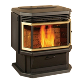
FREESTANDING & FIREPLACE INSERT
•
Warning: If your appliance is not properly installed, a house fire may result. For your safety, follow the
installation directions. Contact local building or fire officials about restrictions and installation inspection
requirements in your area.
•
Please read this entire manual before installation and use of this pellet fuel-burning room heater. Failure
to follow these instructions could result in property damage, bodily injury, or even death.
•
Save these instructions.
•
Some surfaces become hot at higher feeding rates. To prevent potential burns, avoid contact with those
areas.
•
This heating unit must serve as a supplementary heat source. An alternative heat source should be
available in the home if needed. The manufacturer cannot be responsible for additional heating costs
associated with the use of an alternative heat source.
•
It is highly recommended that the user buys this product from a retailer who can provide installation and
maintenance advices.
Professional installation is highly recommended
MODEL HYBRID-35
OWNER'S MANUAL
Manufactured by:
Stove Builder International Inc.
Quebec City (Quebec)
CANADA
45260
Advertisement
Table of Contents

Related Manuals for Osburn HYBRID-35


Summary of Contents for Osburn HYBRID-35
- Page 1 MODEL HYBRID-35 FREESTANDING & FIREPLACE INSERT OWNER’S MANUAL • Warning: If your appliance is not properly installed, a house fire may result. For your safety, follow the installation directions. Contact local building or fire officials about restrictions and installation inspection requirements in your area.
-
Page 2: Introduction
INTRODUCTION Thank you for purchasing the HYBRID-35 pellet stove & insert. You are now prepared to burn wood in the most efficient, convenient way possible. To achieve the safest, most efficient and most enjoyable performance from your stove, you must do three things: 1) Install it properly; 2) Operate it correctly; and 3) Maintain it regularly. -
Page 3: Safety Precautions
SAFETY PRECAUTIONS • • Do not operate your stove if you Keep foreign objects out of the hopper. smell smoke coming from it. Turn it off, monitor it, and call your dealer. DO NOT UNPLUG IT • • Never use gasoline, gasoline-type Do not throw this manual away. -
Page 4: Table Of Contents
TABLE OF CONTENTS INTRODUCTION ..................................2 SAFETY PRECAUTIONS ............................... 3 TABLE OF CONTENTS ................................4 FREESTANDING INSTALLATION............................6 HYBRID-35 FREESTANDING PELLET STOVE .................... 6 PREPARATION ..............................6 CLEARANCES ..............................6 COMBUSTION AIR SUPPLY ........................... 8 WHEN OUTSIDE AIR IS NOT USED ......................8 VENTING ................................ - Page 5 CLEANING ............................... 23 BLOWERS AND PRESSURE SWITCH PROBE .................... 24 CHIMNEY CLEANING ............................ 24 RECOMMENDED MAINTENANCE SCHEDULE ..................25 REMOVAL AND REPLACEMENT OF DOOR GLASS ................25 TROUBLESHOOTING ................................26 STOVE SHUTS OFF AND SHOWS WARNING CODE “P” ................. 26 STOVE SHUTS OFF AND SHOWS WARNING CODE “E”...
-
Page 6: Freestanding Installation
FREESTANDING INSTALLATION HYBRID-35 FREESTANDING PELLET STOVE BACK WALL Width: 22 1/2” Height: 29” 3" Depth: 24 1/2” 2" * Weight: 195 lbs. Flue size: 3” or 4” Hopper Capacity: Up to 35 lbs. (This can vary slightly depending on pellet size, length, and diameter) EPA status: exempt Burn rate: 1.3 lbs to 4.1 lbs per hour 6"... -
Page 7: Clearances
CLEARANCES The HYBRID-35 has been tested and listed for installation in regular and mobile homes.(refer figure 1 & 2) FLOOR PROTECTION: minimum 6” in the front and 6” on each side. The stove must be placed on a continuous (grouted joints) non-combustible material such as ceramic tile, cement board, brick, 3/8”... -
Page 8: Combustion Air Supply
COMBUSTION AIR SUPPLY For a mobile home installation the stove must be connected to an outside source of combustion air. A 3” inside diameter metallic pipe, either flexible or rigid, may be attached to the inlet at the stove’s rear (refer to figures 4, 5 EXHAUST &... -
Page 9: Filters Installation And Cleaning
FILTERS INSTALLATION AND CLEANING The two filters for your convection blowers are supplied with the owner’s manual. Although the filters are not mandatory, they are useful to prevent dust from being dispersed into the room where the stove is located. If you install the filters, please make sure that they are cleaned on a regular basis as per our recommended maintenance schedule. -
Page 10: Equivalent Vent Lenght (Evl)
EQUIVALENT VENT LENGHT (EVL) The longer the run of pipe in your installation, the more restriction there is in the system. Therefore, larger diameter pipe should be used for longer runs. • Use 4” pipe if you have more than 15 feet of Equivalent Vent Length (EVL). -
Page 11: Vertically With New Chimney System
B. VERTICALLY WITH NEW CHIMNEY SYSTEM (Refer to Figure 17 – Venting through roof) NOTE: Follow Vent chimney manufacturer’s instructions. OPTION: To achieve a centered vertical installation, a 45º elbow and a clean-out tee can be used to offset the pipe from the exhaust outlet to the rear center of the stove. -
Page 12: Vertically Into Existing Masonry Fireplace
VERTICALLY INTO EXISTING MASONRY FIREPLACE VERTICAL ROOF VENT 18" NOTE: Follow Vent chimney manufacturer’s instructions. 3" Have the masonry chimney inspected by a qualified chimney sweep FOLLOW CHIMNEY OR VENT MANUFACTURER'S TOP PLATE or installer to determine its structural integrity. INSTRUCTIONS You must run a pipe from the stove outlet to 18 inches above the top of the chimney. -
Page 13: Insert Installation
INSERT INSTALLATION The detailed instructions required to assemble the faceplate are supplied with the faceplate kit. INSERT INTO EXISTING MASONRY FIREPLACE NOTE: Follow pipe manufacturer’s instructions. FACEPLATE Have the masonry chimney inspected by a qualified chimney sweep or installer to determine its structural integrity. -
Page 14: Clearances
CLEARANCES COMBUSTIBLE SHELF 10 1/2" 11" 6" 7" FLOOR 6" PROTECTION Figure 36 Clearances DOOR OVERLAY INSTALLATION In order to complete the assembly of your OSBURN HYBRID-35, you need to install the door overlay. 1- Position the overlay on the door frame and fix it in place from behind using the 4 screws. -
Page 15: Operation
OPERATION DISPLAY BOARD PROPER FUEL THIS STOVE IS APPROVED FOR BURNING PELLETIZED WOOD FUEL ONLY! Factory-approved pellets are those 1/4” or 5/16” in diameter and approximately 1” long. Longer or thicker pellets sometimes bridge the auger flights, which prevents proper pellet feed. Burning wood in forms other than pellets is not permitted. -
Page 16: Unit Controls
UNIT CONTROLS The blowers and automatic fuel supply are controlled from the panel on the HYBRID-35. The control panel functions are as follows: Note: To display the available functions, just touch the control board at any place Select the desired function *The display will turn itself off after 2 minutes. -
Page 17: Combex Tm
COMBEX Your stove uses a unique patented technology called COMBEX. As opposed to most other pellet stoves, which use only an exhaust blower, your HYBRID-35 uses a motor on which are mounted two housings with impeller blades. One housing serves for combustion, and the other for exhaust. -
Page 18: Shutdown Procedure
SHUTDOWN PROCEDURE Turning your OSBURN stove off is a matter of pressing on the control panel. The blowers will continue to operate until internal firebox temperatures have fallen to a preset level. The stove cannot restart before it has completely shut down. SAFETY FEATURES Your stove is equipped with a manual reset high temperature switch (also called heat sensor or heat switch). -
Page 19: Operating The Stove Using A Thermostat
OPERATING THE STOVE USING A THERMOSTAT A thermostat will help you maintain a constant house temperature automatically. A millivolt or 24 Volt thermostat is required. A fixed wall mount or remote model can be used. THERMOSTAT INSTALLATION • Unplug the stove from the power outlet. •... -
Page 20: Modes
MODES THERMOSTATIC MODE • To engage this mode, the thermostat icon must be pushed upon starting the stove. The heat setting is then selected using the “Heat Level” selector. When set in thermostatic mode, the stove will automatically run at the heat level selected until the set room temperature is reached. -
Page 21: Operating Safety Precautions
OPERATING SAFETY PRECAUTIONS PLEASE READ THIS! a. If you notice a smoldering fire (burnpot full but no visible flame) AND a heavy smoke buildup in firebox, immediately TURN OFF the stove, but DO NOT unplug it. Do not open the door, change the damper setting or tamper with any controls on the stove. -
Page 22: Maintenance
MAINTENANCE FAILURE TO CLEAN AND MAINTAIN THIS UNIT AS INDICATED CAN RESULT IN POOR PERFORMANCE AND SAFETY HAZARDS. NEVER CLEAN WHEN HOT. NOTE: Inspect burn pot periodically to see that holes have not become plugged. If so, clean thoroughly. BAFFLE ASH REMOVAL The HYBRID-35 stove has an ash drawer located under the firebox (not available for insert installation*). -
Page 23: Vaccum Use
VACCUM USE If a vacuum is used to clean your stove, we suggest using a vacuum designed for ashes. Some regular vacuums and shop vacs leak ash into the room. Your vacuum or shop vac may have a special filter or bag available to eliminate this leakage. CLEANING Heat Exchange Tubes –... -
Page 24: Blowers And Pressure Switch Probe
BLOWERS AND PRESSURE SWITCH PROBE PROBE CONNECTOR DANGER: RISK OF ELECTRIC SHOCK. DISCONNECT POWER BEFORE SERVICING UNIT. • Blower Cleaning – Over a period of time, ashes or dust may collect on the blades of both the combustion/exhaust blower and convection blower. -
Page 25: Recommended Maintenance Schedule
RECOMMENDED MAINTENANCE SCHEDULE Use this guide for average-conditions of operation. Weekly Twice a year Annually Components Daily or after or after +/- 10 bags +/- 25 bags per ton of pellets Burn Pot Empty Empty / Brush Glass Wipe Clean Activate cleaning rod Activate cleaning Heat Exchanger Tubes... -
Page 26: Troubleshooting
TROUBLESHOOTING When your stove acts abnormally, the first reaction is to get help. This guide may save you time and money by enabling you to resolve simple problems yourself. Problems can be caused by: 1) poor fuel; 2) poor operation or maintenance; 3) poor installation; 4) component failure; 5) factory defect. You can usually solve problems related to 1 and 2. -
Page 27: Stove Shuts Off And Shows Warning Code "E
STOVE SHUTS OFF AND SHOWS WARNING CODE “E” Possible Causes: Possible Remedies: (Unplug stove first when possible) The hopper is empty. Refill the hopper. The burn pot holes are blocked. Remove the burn pot and clean it thoroughly. The air damper is too far open for a low feed setting. If burning on the low setting, you may need to close the damper all the way slide the air supply toward the minimum setting. -
Page 28: Stove Feeds Pellets, But Will Not Ignite And Shows Warning Code "L
STOVE FEEDS PELLETS, BUT WILL NOT IGNITE AND SHOWS WARNING CODE “L” Possible Causes: Possible Remedies: Air damper open too far for ignition. Adjust the air supply toward the minimum setting for startup. In some situations, it may be necessary to have the damper completely closed for ignition to take place. After there is a flame, the damper can then be adjusted for the desired feed setting. -
Page 29: Stove Stops Feeding Pellets And Shows Warning Code "H
STOVE STOPS FEEDING PELLETS AND SHOWS WARNING CODE “H” Possible Causes: Possible Remedies: One of the two L-250 automatic high temperature switches has been The L-250 automatic high temperature switches are located on the top and tripped. bottom of the auger housing They send a signal to the control board if the auger housing overheats. -
Page 30: Smoke Smell Coming Back Into The Home
SMOKE SMELL COMING BACK INTO THE HOME Possible Causes: Possible Remedies: There is a leak in the vent pipe system. Inspect all vent pipe connections. This is a pressurized exhaust system. All vent connector joints must be sealed and fastened in accordance with the pellet pipe manufacturer's instructions to ensure consistent performance and avoid smoke and ash spillage. -
Page 31: Warning Codes
WARNING CODES MESSAGE CORRESPONDING WARNING Pressure switch error. L-250 automatic high temperature switches, located under and above the auger. L-250 manual reset high temperature switch, located beside convection blower. Hopper is empty Lighting error. Hopper lid stayed open more than 3 minutes. Inverted polarity in power outlet.(Will not keep the stove from operating) Power outage Igniter fuse blew up... -
Page 32: Electrical Diagram
ELECTRICAL DIAGRAM THERMOSTAT HOPPER LID TERMINALS SWITCH N.O. N.O. CONTROL BOARD DISPLAY BOARD THERMISTOR L2(LINE COMMON) L1(LINE HOT) L1(LINE NO CONNECTED) FRAME GROUND L-250 RESET N.C. AIR FLOW PRESSURE SWITCH N.O. AUGER COMBUSTION/EXHAUST IGNITER MOTOR BLOWER L-250 N.C. F-160 CONVECTION N.O. -
Page 33: Replacement Parts
REPLACEMENT PARTS Contact an Authorized OSBURN Dealer to obtain any of these parts. Never use substitute materials. Use of non-approved parts can result in poor performance and safety hazards. ITEM PART # Airflow Pressure Switch 44029 Air Switch Hose 49004 Auger Motor 44038 Burn Pot... -
Page 34: Appendix A
APPENDIX A HORIZONTAL AND VERTICAL VENT CHART If you plot your venting system configuration on this chart, your wall or Possible Vertical roof termination should be vent length (feet) within the grid. Possible Horizontal vent length (feet) Let’s imagine an installation consisting of a horizontal vent coming out at the back of the stove on a total distance of 8 feet. This horizontal run is followed by a Tee and a 6-foot vertical rise. -
Page 35: Appendix B
APPENDIX B Fabriquant de poêle international inc. INSTALLATION DIAGRAM Stove Builder International Inc. 1700, rue Léon-Harmel, Québec (Québec) G1N 4R9 DRAW YOUR INSTALLATION Phone : (418) 527-3060 Fax : (418) 527-4311 1 SQUARE = 1 F00T E-mail : tech@sbi-international.com Web site : www.drolet.ca Installation int. -
Page 36: Osburn Limited Lifetime Warranty
OSBURN LIMITED LIFETIME WARRANTY The warranty of the manufacturer extends only to the original consumer purchaser and is not transferable. This warranty covers brand new products only, which have not been altered, modified nor repaired since shipment from factory. Proof of purchase (dated bill of sale), model name and serial number must be supplied when making any warranty claim to your OSBURN dealer.
Need help?
Do you have a question about the HYBRID-35 and is the answer not in the manual?
Questions and answers