
Related Manuals for 3D Systems projet mjp 2500


Summary of Contents for 3D Systems projet mjp 2500
- Page 1 Published on Product Information Center | ProJet MJP 2500 (http://infocenter.3dsystems.com/projetmjp2500) Home > User Guide...
- Page 2 USER GUIDE...
- Page 3 ® PROJET MJP 2500 & MJP 2500 PLUS User Guide Rev A Please refer back to http://infocenter.3dsystems.com/projetmjp2500/ for the most up-to-date User Guide...
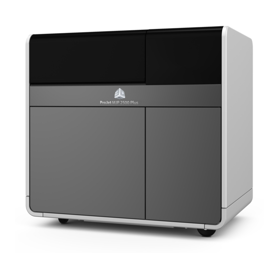
- Page 4 INTRODUCTION The ProJet MJP 2500/2500Plus 3D printer system is a Multi-Jet Printer (MJP) printer. The solid imaging 3D printer produces plastic prototype parts from 3D solid Computer-Aided Design (CAD) models and through the 3D printer system client software. The parts are generated in a rapid prototype (RP) environment. The primary features of the printer are the user interface, build chamber including the print engine, and the material delivery drawer, which contains the materials and waste bag.
-
Page 5: Important Safety Information
Only certified service personnel that have completed the 3D Systems service training may perform tasks they are authorized and certified to complete. Do not ignore warning signs posted during 3D printer system service operations. If an error message appears on the 3D printer system’s User Interface refer... - Page 6 Material Handling and Safety Prior to using the ProJet MJP 2500 and 2500 Plus, users should be aware of potential hazards which may result in exposure to uncured part material, such as removal of the material waste bag and handling part material cartridges.
- Page 7 Recertification Date Always check material "Recertification Date" before use. Do not load material cartridges into the ProJet MJP 2500 or 2500 Plus if the cartridge date has expired. When an expired cartridge is inserted, the printer will reject it. If a job is printing when the cartridge expires, it will to continue to complete the job before declaring the cartridge is no longer available for use.
- Page 8 Dispose of your uncured parts and waste materials according to your local environmental regulatory agency. If assistance is needed, contact 3D Systems certified Partners or 3D Systems Technical Support. 3D Systems assumes no liability or responsibility for proper disposal of uncured part material. Proper disposal of uncured part material is the sole responsibility of the user.
- Page 9 PROJET MJP 2500 PRINTER SERIES FEATURES This section describes the various features for your ProJet MJP Professional Printers.
- Page 10 PROJET 2500 FEATURES ProJet MJP 2500 - Entry Level Printer with Basic Material Set Build Mode High Definition (HD) Resolution (xyz) 800 x 900 x 790 DPI Build speed 1 Lane: 0.26 2 Lanes: 0.19 3 Lanes: 0.12 (in/hr) in Z mm/hr 1 Lane: 6.6...
- Page 11 PROJET MJP 2500 PLUS FEATURES ProJet MJP 2500 - Entry Level Printer with Basic Material Set Build Mode High Definition (HD) Resolution (xyz) 800 x 900 x 790 DPI Build speed 1 Lane: 0.26 2 Lanes: 0.19 3 Lanes: 0.12...
-
Page 12: At A Glance
AT A GLANCE The three dimensional solid parts consist of two materials (support material and part material). The support material is a wax based material providing adhesion to print platform, as well as, providing material used to produce supports required to build the your part. The part material is an ultraviolet (UV) curable material. - Page 13 ProJet 2500 Installation Guide The Installation Guide details the procedures required to properly install and set up the ProJet 2500 3D Printer at the customer’s site. Only a 3D Systems Certified Field Service Engineer or a Certified Reseller is allowed to install the 3D printer system. An electronic version of this document is available at https://3dscentral.3dsystems.com.
- Page 15 USER INTERFACE User Interface The User Interface is located on the top of the printer to the right. There are five main screens that contain sub menus that allow the user to perform a variety of functions to control the printer. These five screens and their menus are: Status Tab (A) The first tab on the UI.
- Page 16 Materials Tab (C) Displays information about the Part and Support materials loaded in the printer. Material Status -Displays the level of material in both the Support and Part Cartridges. Part Message - Displays messages relating to the part material loaded in the printer. Support Message - Displays messages relating to the support material loaded in the printer.
- Page 17 1. Printer Info - Information about the printer can be found here. 2. Diagnostics - Many diagnostic procedures can be run under the Diagnostics button. See Diagnostics Menus below for more information. 3. Material Change Wizard - To change from one type of material to another there is a flush operation that you have to perform to ensure all of the first material is out of the printer before adding a new material.
-
Page 18: Settings Screen
1. Inspect Planarizer Wiper Blade - Select this routine to inspect the planarizer blade for excess buildup. See Troubleshooting section for procedure. 2. Inspect Planarizer Ducts - This is a routine that will allow the user to inspect and clean the ducts in the planarizer. See Troubleshooting section for procedure. - Page 19 4. Date Time Settings - To change or setup the date and time click on Date Time Settings. 5. APP Settings - Controls the UI brightness level and contains information about the UI itself...
- Page 20 PRINTER SETUP...
- Page 21 (>60 days). UI will begin to power up. This may take a minute or two for the screen to come on. When the UI is booted up the 3D Systems logo will appear and then the Status screen will appear.
- Page 22 CHANGING WASTE BAG The UI will instruct the user when it is time to change the Waste Bag. Follow these steps to change the waste bag. NOTE: Even though the waste bag may not appear full when the user is notified to change it, it is highly recommended to replace the waste bag when prompted to avoid unnecessary overflow and mess.
- Page 23 Remove waste bag. NOTE: If the waste bag is stuck to the liner when you attempt to remove it, replace the entire liner and bag to prevent the bag from tearing and causing material to leak into the receptacle. Waste bags can be ordered using part number 311215-00. With each order you will receive 30 bags and 1 liner.
- Page 24 MATERIAL CARTRIDGE REMOVAL AND INSTALLATION When a material cartridge is empty and needs to be replaced, or if a partially filled container needs to be replaced with a full container, perform the following procedure. NOTE: It is important to verify the type of material currently in the MDM before proceeding with these steps. Removing Material Cartridge NOTE: Cartridges cannot be removed from a cold printer.
- Page 25 Press the release button (C) on the front. You will hear the cartridge release. Pull the cartridge out of the slot. Dispose of the empty cartridge according to local regulations. Wearing nitrile gloves and either protective sleeves or a lab coat to protect arms, use a disposable paper towel and wipe all material from the container seal assembly, if necessary you can use some isopropyl alcohol on the paper towel to wipe up the excess material.
- Page 26 If drawer is not already open, push to unlock drawer. Pull open the MDM drawer. NOTE: The steps to install a support cartridge are the same as installing a part cartridge. NOTE: To install cartridges into the MDM drawer properly ensure that the small cap be installed away from the user. NOTE: It is important to verify the cartridges have been audibly clicked into place, have material in them, and the cartridge caps properly ventilated;...
- Page 27 Close the MDM drawer (B), by pushing in the dimple at the top until it’s latched securely. Check the material level under the Materials tab (C) on the UI to ensure cartridge is ceded properly into MDM and ready to print.
- Page 28 PRINT PLATFORM REMOVAL AND INSTALLATION Personal Hygiene Always wash hands thoroughly with soap and water after handling parts and/or material. Never eat or drink without washing hands first. NOTE: Make sure you are wearing nitrile gloves and protective clothing before performing any of the following procedures. Always protect yourself from possible exposure to materials.
- Page 29 A message will display (see below) asking user to confirm that the platform is clean, verify the platform is clean. NOTE: Always be sure you are installing a print platform that is clean on both sides to avoid any printing issues. Also, confirm that the print platform is free from damage due to any drops or dings.
- Page 30 STEPS FOR PRINTING YOUR FIRST PRINT Once the printer is powered up, allow time for the printer to warm up and the materials in the MDM (Material Delivery Drawer) to heat up before accessing the drawer and inserting cartridges. If no cartridges are installed, or cartridges are installed but cold, it can take 20 minutes before the material deliver system is warm enough to insert or remove cartridges.
- Page 31 Check the percentage of material in the waste bag. If there is not going to be enough for your build, select Replace Waste Bag (2). Wearing nitrile gloves, open the MDM drawer. NOTE: The MDM Drawer will not open until the printer is warm. NOTE: For larger builds it may be necessary to change the waste bag in the middle of printing.
- Page 32 NOTE: If you do not have 3DSPRINT loaded on your computer you can obtain a copy at https://3dsystems.teamplatform.com/l/bf5a2229. Printing a Part To print your first part follow these instructions. NOTE: Ensure print platform is installed prior to printing a part. See Print Platform Installation for more information.
- Page 33 Selecting Material 1. At this point you must select the desired material your part will be printed with. Double Click desired material (3a) and select Next (3b). NOTE: If you need to change the material from what is currently installed in the printer, you will need to perform an MCO (Material Changeover).
- Page 34 Printing the File 1. In the Print Setup (1) tab select File > Import (2). 2. Navigate to the file you wish to print, click Open.
- Page 35 Select Auto Place (4a) > Set (4b). 4. Select Add to Print Queue. (6a) 5. A verification box will come up. Check the file name and when you are sure it is the correct file, select Add to Queue (6b).
- Page 36 6. Print Queue will display current parts being printed (7) and where your job is in the queue. Send Job to Print 1. On the UI select the Prints tab (1). 2. Select the job to print (2). 3. Select the Send to Print (3) button.
- Page 37 PRINTER SHUTDOWN Storing Printer for Extended Time Frame When the printer is going to be stored for an extended period of time (>60 days) you will need to call a Certified Partner to set up a service call for a Dry Out procedure to be performed.
- Page 38 Printer Shutdown screen will appear next. This lets the user know that the printer is shutting down and not to take any action. A message will then come up that states it is now safe to turn the power switch off. NOTE: Unless the printer will be idle for an excessively long time (>60 days) it is not necessary to shut it down.
- Page 39 MCO - MATERIAL CHANGEOVER PROCEDURE For successful build jobs, when a user wants to switch from one part material to another, a Material Changeover (MCO) must be performed. NOTE: Please ensure you have replaced the waste bag with a new empty one PRIOR to starting the Material Changeover Procedure.
- Page 40 The next step is to replace the waste bag before MCO process begins. If waste bag needs to be changed, select Replaced Waste Bag, after bag has been replaced. If the waste bag is empty already, select Use Existing Bag. The next screen shows that the Material Change Wizard has started.
- Page 41 At the next pop up you will need to insert two MCO Cleaner 2500 cartridges and close the MDM drawer. Select OK. NOTE: If the cartridges are cold the process will take an additional 30 minutes to allow material to warm before continuing. The next screen alerts user what step they are in the Material Changeover Procedure.
- Page 42 When this pop up comes up, remove the cleaner cartridges out of the MDM and close the drawer. Select OK. Printer needs to flush out the Cleaner material. When prompted the new part material cartridges need to be inserted into the MDM. Select OK. NOTE: If the cartridges are cold the process will take an additional 30 minutes to allow material to warm before continuing.
- Page 43 This screen is the next step, no action is required. Once the Material Changeover Process is complete a confirmation screen will appear. The next screen displays if Cancel is selected. If Stop was selected in error Select No. If user wants to stop the MCO, select Yes.
- Page 45 MAINTENANCE Operator Maintenance The UI provides reminders when routine maintenance is required. NOTE: The printer must be at a Ready state and a clean print platform installed before performing any of the routines below: There are several ways a user can tell if maintenance needs to be performed on the printer. A pop up will appear on the UI letting the user know The user can select Operator Maintenance from the UI and see when the next maintenance procedure will need to be performed If the user sets up email alerts, an email alert will tell the user maintenance needs to be performed...
- Page 46 Photo below illustrates a filter that needs to be changed. Photo below illustrates a filter that is clean and new. Replacing the Filter Screen There is a screen that is placed above the particulate filter to add extra filtering protection for the filter. This screen will need to be replaced periodically (P/N 311317-00).
- Page 47 Wearing nitrile gloves, lift panel up and pull out old screen. Insert clean screen in its place. Screen may be cleaned by holding over a approved waste disposal receptacle and brushing off loose particles from screen. Screen may then be wiped clean using a paper towel with isopropyl alcohol. If screen has deposits that will not come off, it may be time to replace it with a new one.
- Page 48 Close panel and tighten thumb screw.
- Page 49 INSPECTING AND CLEANING PLANARIZER DUCTS Inspect and Clean Planarizer Ducts Material can get trapped and built-up in the ducts of the planarizer. It is important to periodically inspect and clean these areas. Follow these steps to inspect and clean the planarizer ducts. NOTE: Always wear nitrile gloves when inspecting and cleaning planarizer ducts.
- Page 50 Using a foam swab, gently wipe out excess material from holes. For stubborn areas, use a bit of isopropyl alcohol on the foam swab before wiping. When all material has been cleaned up, close top door and carriage will return to Home position. Dispose foam swabs in proper disposal container.
- Page 51 INSPECT PLANARIZER BLADE Inspect Planarizer Blade The planarizer blade will need to be inspected periodically and wiped off. Excess material can build up over time. CAUTION: Use care when cleaning the blade, it can easily be damaged. Once blade has been cleaned, close the cover and the top door. In the UI click on Tools >...
- Page 52 Once blade has been cleaned, close the cover and the top door. Open planarizer cover to access wiper blade assembly. Close top cover, carriage will return to home position. On the user interface, select Tools>Operator Maintenance>Planarizer Wiper Blade>Yes, that it has been cleaned.
- Page 53 CLEAN PRINT CARRIAGE OPTICAL HOME SENSOR Clean Print Carriage Optical Home Sensor Pixie Dust Removal from Opto Sensors Over time pixie dust will accumulate on the opto sensors and will need to be cleaned off. Follow this procedure for cleaning the Opto sensors. NOTE: Always wear nitrile gloves when cleaning the Opto sensors.
- Page 54 After all the excess pixie dust is cleaned off the sensors, close the carriage cover. Close the Top Door and carriage will move back into position.
- Page 55 REMOVING PIXIE DUST FROM UV ASSEMBLIES (LEFT AND RIGHT) Removing Pixie Dust from UV Assemblies (right and left) Over time, the UV assemblies accumulate a buildup of pixie dust (light coating of material particles) that will need to be wiped off with a lint free cloth and isopropyl alcohol.
- Page 56 NOTE: It may be helpful to shine a flashlight where you are wiping for better visibility. When material is removed, carefully remove the paper towel and dispose of properly. Left UV Assembly Lift left UV lamp cover up and gently wipe the entire underside of the UV Assembly with a lint free cloth moistened with isopropyl alcohol. When finished, close cover and top door.
- Page 59 CONFIRM JETS Jet Check Routine Perform this procedure to confirm that all printhead jets are working properly if: You are installing the printer for the first time, or The machine has not recently completed a print, or Completed prints appear to be missing material (support or part material) Items Needed: Pastel office paper (up to 6 sheets) Tape...
- Page 60 Wearing nitrile gloves, take two sheets of pink pastel paper (aligning the edges) and tape them down to the build platform as shown. The pink paper is supplied with the printer. Ensure you are always using two sheets of paper to allow for the test to be visible.. NOTE: The paper needs to be flat and the perimeter needs to be securely taped to the print platform to avoid any raised edges or surfaces as shown in the picture below.
- Page 61 Thermal issues in the material delivery system Cabling Electronics and circuit boards Head maintenance system Printhead issues Jet Check Evaluation Criteria There are three criteria in which to evaluate the Jet Check Test Print. A fail in any of the three criteria results in a fail for the Jet Check and will require the procedure to be repeated or the printer to be serviced.
- Page 62 Pass Samples If all gaps within a single row have 5 lines or more between them, proceed to the third evaluation. Evaluation Criterion 3 of 3: Are there at least 2 lines between a gap in a row above or below? When performing this evaluation, only compare rows of part material to other rows of part material and only compare rows of support material to other rows of support material.
- Page 63 Pass Sample...
- Page 65 CLEANING EXTERIOR SURFACES Do not remove any outer panels when cleaning the printer. Panels must only be removed by qualified 3D Systems Technical Support Representatives. Remove dust from outer surfaces of printer by wiping with a clean, dry, lint-free cloth.
- Page 66 CLEANING POLYCARBONATE TOP DOOR Polycarbonate Top Door should be cleaned with a non-abrasive cleaning and damp cloth. Gently wipe surface using dampened cloth to remove debris. CAUTION: Do not use cleaners such has Windex and paper towels to clean polycarbonate surfaces. Use only a non-abrasive cleaner and a chem wipe or a lint free cloth.
- Page 67 CLEANING PRINT PLATFORM Any time parts are processed, it is a good practice to clean the print platform and re-insert it into the printer. Follow these steps for cleaning the platform: Use a flat razor blade or putty knife to scrape any excess support material off of the platform. Be careful not to scratch the black coating on the platform. Spray the platform with isopropyl alcohol (IPA) and wipe with paper towels.
- Page 68 CLEANING THE USER INTERFACE Remove any printed parts before cleaning the user interface. This will prevent the printer from initiating any actions if controls are accidently pressed. Spray a water-based solvent such as Simple Green onto a lint-free soft cloth; do not wipe with a dry cloth or spray cleaner directly onto touch screen. Gently wipe dirt and part material residue from touch screen using an ammonia-based glass cleaner on a clean, lint-free cloth.
- Page 69 MDM MAINTAINANCE The following general maintenance procedures provided must be accomplished to help maintain high part yield and to reduce the printer down time. When changing material cartridges, material may be present in the MDM receptacle after the cartridge is removed. If a large pool of material is present (bottom is submerged and walls of the cartridge receptacle are reached), do not place a clean material cartridge into the receptacle, call your reseller/partner.
- Page 70 ROUTINE MAINTENANCE It is recommended to keep the printer clean and free of debris between builds. Gently wipe beauty plate off with a lint free cloth and isopropyl alcohol after each build. The outside of the printer can be wiped off with a non abrasive cleaning and a damp cloth.
-
Page 71: Troubleshooting
TROUBLESHOOTING The Troubleshooting section is designed to help the user diagnose any anomalies that is happening with the printer before having to call for service. Most of the everyday things that can occur are listed in this section. If this section does not answer the question or solve the problem, contact your Certified Partner for service. - Page 72 SHRINK COMPENSATION Shrink Compensation for ProJet VisiJet® Materials Material shrinkage occurs in thermosets as they transition from liquid state to solid state during the curing process. The 3DSPRINT Client Software has features that allow the user to compensate for the natural shrinkage of the material in order to fine tune the accuracy of a part.
- Page 73 Open 3DSPRINT Client Software and select Printer Tools. Select the Printer Settings. Select the Add Button.
- Page 74 Give this new Shrink Compensation a name, enter the new values, click SET. Now the printer is defaulted to the new set of shrink compensation values. The bottom right corner information window is providing the new maximum printable size for XYZ accordingly per shrink compensation. You can now load jobs and print to the printer using these Shrink Compensation values.
- Page 75 Method B Select Shrink Compensation Values for this material. Open 3DSPRINT client software and select the Printer. Select the printer (use cursor to show printer information) you wish to print the job with and then click Next.
- Page 76 Select material for the job, click Next.
- Page 77 Select Print Mode, and then click Next. Pick your Build Style with Shrink Compensation values entered in Method A and click Set.
- Page 78 Now the printer is set to print with the selected shrink compensation values. The information window is showing maximum printable size for XYZ accordingly per Shrink Compensation. You can now load jobs and print to this printer with these particular set of Shrink Compensation values. Method C Apply Shrink Compensation Values in each part Enter Scaling Factor for adjustment build...
- Page 79 Repeat Step 2 for any other parts which may need shrink compensation added to the job. Using Method C allows you to add different shrink compensation values for different parts. Now this job is ready to print with the chosen shrink compensation values for the parts. You can now add the job to the Print Queue for printing.
- Page 80 PRINTER STATUS AND FAULT CODE RECOVERY The ProJet MJP 2500 uses codes to identify various fault or status conditions with the printer: Status about the device, for example, cartridges are low on material User-clearable faults, by the user performing cleaning procedures Printer-clearable faults, where the printer is automatically attempting recovery Service required faults, which can only be resolved by a certified partner...
- Page 81 Printer Status Code Issue Description Customer Troubleshooting Steps 94-203 Planarizer Contact Calibration Planarizer Contact Calibration Failed prior to printing, the 1. Access Platform from the UI > Status Tab Failed printer calibrates the planarizer gap. If it fails, the printer will 2.
- Page 82 NON-FAULT CODE RECOVERY Problem Description Troubleshooting Steps The printer will not power up The UI is off and there are no sounds coming from the 1. Turn the power switch off printer. 2. Wait for 30 seconds 3. Unplug the power cord 4.
- Page 83 Problem Description Troubleshooting Steps UI black, machine powered on The machine is powered on, fans and other machine noises 1. Turn the power switch off are observed. 2. Wait for 30 seconds 3. Unplug the power cord 4. Wait for 10 seconds 5.
- Page 84 Problem Description Troubleshooting Steps Status envelope - Print platform has A print job was completed and a new print platform has been 1. Select Access Platform from the printer UI. material on it installed. The next print job will not start, status envelop 2.
- Page 85 PART QUALITY ISSUE RECOVERY Problem Description Troubleshooting Steps Missing Material Missing Jets: Missing material in part Part has material missing in the left to right direction. If the 1. Perform Jet Check procedure, see Confirm Jets (left to right) part is across multiple lanes (front to back) missing material 1.
- Page 86 Problem Description Troubleshooting Steps Color mixing The printed material appears to have small areas of lighter or 1. Inserting a different part material color can result in a darker color small amount of color mixing which may show up on the printed part.
- Page 87 Problem Description Troubleshooting Steps Part won't adhere to the print The printed part is not building correctly on the print 1. Never print with a cold print platform. When using a print platform platform, the support (wax) material won't adhere to the print platform where a part was just removed, allow the print platform.
- Page 88 In Japan, call (+81) 3 5451 1690 General ProJet 2500 service procedures must be performed only by a 3D Systems-certified service technician unless this guide explicitly states otherwise. If your 3D printer system needs service, contact 3D Systems Technical Support at the following numbers:...
- Page 89 3D Systems, Inc. The licensed user, in the name of whom this document is registered (the “Licensed User”) does not have the right to copy, reproduce, or translate this document in any way or to any media without the prior written consent of 3D Systems, Inc. No copies of the document may be sold or given to any person or other entity.
- Page 90 La Déclaration de CE de Conformité We, 3D SYSTEMS, INC. herewith declare that the following described 3D printer system in our delivered version complies with the basic safety and health requirements of the EC Directive 2006/42/EC of the European Parliament and of the Council of 17 May 2006, based on its design and type, as brought into circulation by us.
- Page 91 Corporate Headquarters 3D Systems Europe, Ltd. Manufactured in USA for 3D Systems Corporation Mark House, Mark Road Fabriqué dans l’USA pour 333 ThreeD Systems Circle Hemel Hempstead Company Name: Rock Hill, SC 29730 Hert HP2 7UA United Kingdom Brian Alexander...
- Page 92 .3dprint File - Files that have been created and saved by the client software 3DSPRINT. 3DSPRINT - The client software used to create parts and send them to the printer. Copyright © 3D Systems, Inc. All rights reserved. | Source URL: http://infocenter.3dsystems.com/projetmjp2500/user-guide...
Need help?
Do you have a question about the projet mjp 2500 and is the answer not in the manual?
Questions and answers