Table of Contents
Advertisement
Quick Links
Advertisement
Table of Contents

Related Manuals for Ducati MULTISTRADA 1200 ENDURO


Summary of Contents for Ducati MULTISTRADA 1200 ENDURO
- Page 2 Although the manual includes fully updated information at the time of print, Ducati Motor Holding S.p.A. therefore reserves the right to make changes without prior notification or without incurring obligations. For this reason, you may note discrepancies when comparing some illustrations with your motorcycle.
- Page 3 Owner's manual US/CANADA...
- Page 4 We'd like to welcome you among Ducati enthusiasts and congratulate you on your excellent choice of motorcycle. We imagine you'll be riding your Ducati motorcycle for long trips as well as short daily excursions. Ducati Motor Holding S.p.A. wishes you smooth and enjoyable riding.
-
Page 5: Table Of Contents
California emission control warranty statement Your warranty rights and obligations Manufacturer’s warranty coverage Owner's warranty responsibilities California evaporation emission system Ducati limited warranty on emission control system Introduction Safety guidelines Warning symbols used in the manual Instrument panel (Dashboard) - Page 6 OIL SERVICE or SERVICE DATE or DESMO SERVICE Gear indication Fuel level Warning/Alarm (Warning) Odometer (TOT) Error warnings Engine coolant temperature Side stand warning Clock Fog lights Menu Functions Setting MENU Residual range (RANGE) Customizing the Riding Mode Trip meter 1 (TRIP 1) Customizing the Riding Mode: Engine setting Trip meter 2 (TRIP 2) Customizing the Riding Mode: DTC level...
- Page 7 Bluetooth control unit Keys Power outlet Replacing the battery in the active key Central stand; Duplicate keys Assembling the Ducati side panniers Restoring motorcycle operation via the PIN Using the side panniers CODE USB connection Adjusting windscreen height Steering damper...
- Page 8 Stopping the motorcycle Scheduled maintenance chart Parking Scheduled maintenance chart: operations to be Refueling carried out by the dealer Tool kit and accessories Scheduled maintenance chart: operations to be carried out by the customer Main use and maintenance operations Technical data Checking coolant level and topping up, if Weights necessary...
- Page 9 Routine maintenance record Routine maintenance record...
-
Page 10: Introduction
Safety guidelines Important Your safety and that of others are very important. Possibility of damaging the motorcycle and/or Ducati Motor Holding S.p.A. urges you to ride your its components. motorcycle responsibly. Before using your motorcycle for the first time, Note... -
Page 11: Intended Use
Intended use Attention The maximum weight permitted for the side panniers and top case must never exceed 33 lb (15 Attention kg), divided as follows: This motorcycle is designed for both use on 11 lb (5 kg) max. per side pannier; road and light off road duty. - Page 12 Pay attention to the maximum speed allowed for the tires. When using tires of the M+S category, like Pirelli Scorpion Rally recommended by Ducati, it is necessary not to exceed the speed limit corresponding to the speed index specified for that tire: 118 mph (190 km/h) for Pirelli Scorpion Rally.
-
Page 13: Rider's Obligations
Rider's obligations Attention All riders must hold a driver's license. Some medications may induce sleepiness or other effects that impair reflexes and the ability of the rider to control the motorcycle, which may lead to Attention accident. Riding without a license is illegal and punishable by law. - Page 14 Attention 1) the removal or rendering inoperative by any person, other than for purposes of maintenance, Failure to be wearing a helmet in case of repair, or replacement, of any device or element accident increases the chance of serious injury and of design incorporated into any new vehicle for even death.
-
Page 15: Reporting Of Safety Defects
NHTSA cannot become involved in individual You are strongly recommended to take a riding problems between you, your dealer, or Ducati North course approved by the M.S.F. (Motorcycle Safety America. To contact NHTSA, you may either call the Foundation). -
Page 16: Apparel
Apparel Important Clothing in the use of the motorcycle plays an For your safety this type of clothing must be important role in safety, as the motorcycle provides used in both summer and winter. a person no protection from impact in the same way as an automobile. -
Page 17: Safety "Best Practices
Manual. Exhaust gases are poisonous and may lead to loss of Failure to follow these instructions releases Ducati consciousness or even death within a short time. Motor Holding S.p.A. from any liability whatsoever for During the ride, assume a correct body position and any engine damage or shorter engine life. - Page 18 Important Important The passenger should always hold on to the Visually inspect the tires at regular intervals for grab handles under the seat with both hands. cracks and cuts, especially on sidewalls, bulges or large spots which are indicative of internal damage. Replace them if badly damaged.
-
Page 19: Refueling
Refueling Attention Refuel the motorcycle in an open area and with the In case of malaise caused by prolonged engine switched off. inhalation of fuel vapors, stay outdoors and consult a Do not smoke or ever use flames during refueling. physician. -
Page 20: Carrying The Maximum Load Allowed
Carrying the maximum load allowed Important Your motorcycle is designed for long-distance riding Arrange your luggage or heavy accessories in with the maximum load allowed carried in full safety. the lowest possible position and close to motorcycle Even weight distribution is critical to preserving these center. -
Page 21: Dangerous Products - Warnings
If you install the side panniers (available on thoroughly with soap immediately after use. Keep request from Ducati Parts service), sort out luggage away from children. and accessories according to their weight and... - Page 22 Attention The cooling fan operates automatically: keep hands well clear and make sure your clothing does not get The brake fluid used in the brake system is caught in the fan. corrosive. In the event of accidental contact with eyes or skin, wash the affected area with generous Battery quantities of running water.
-
Page 23: Vehicle Identification Number
We recommend that you note the frame number of your motorcycle in the space below. Frame number Fig 1 PLANT OF DUCATI MANU FACTURE TYPE OF MOTORCYCLE SEQUENTIAL MODEL NUMBER YEAR... -
Page 24: Engine Identification Number
Engine identification number Note These numbers identify the motorcycle model and should always be indicated when ordering spare parts. We recommend that you note the engine number of your motorcycle in the space below. Engine number Fig 3 ENGINE MODEL TYPE SEQUENTIAL YEAR... -
Page 25: Option Kits / Customizations
Multistrada the character that suits you best. TOURING; SPORT; URBAN; ENDURO. Information herein refers to Multistrada 1200 Enduro. Information on any other customization (TOURING, SPORT, URBAN and ENDURO) is indicated only when different from the Multistrada 1200 Enduro. - Page 26 TOURING Fig 5...
- Page 27 TOURING 1) Ducati Performance aluminum side pannier set by Touratech with 22.45 gal (85 lt) total capacity; 2) Handlebar bag; 3) Heated handgrips adjustable through 3 levels.
- Page 28 SPORT Fig 6...
- Page 29 SPORT 1) "Termignoni" carbon type-approved silencer (compliant with EU type-approval requirements); 2) Carbon front mudguard; 3) Billet aluminum clutch and brake fluid reservoir covers.
- Page 30 URBAN Fig 7...
- Page 31 URBAN 1) Aluminum Touratech top case, 10 gal (38 liters); 2) Semi-rigid tank bag with quick fitting; 3) USB hub for charging electronic devices.
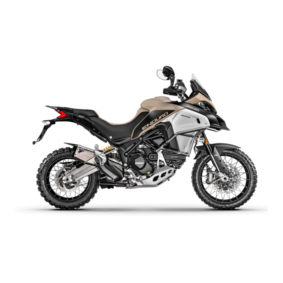
- Page 32 ENDURO Fig 8...
- Page 33 ENDURO 1) Additional lights; 2) Ducati Performance engine protection bars by Touratech; 3) Ducati Performance protection for oil cooler by Touratech; 4) Ducati Performance radiator protection by Touratech; 5) Chain lower protection; 6) Rear brake disk protection.
-
Page 34: Plate Position
Plate position Only Canada Fig 9... - Page 35 DATE: 02/2015 GVWR: 992 Lbs (450 kg) GAWR F: 364 Lbs (165 kg) with 120/70ZR17 tire, MT3.50x17 rim GAWR R: 628 Lbs (285 kg) with 190/55ZR17 tire, MT6.00x17 rim Recomended tire cold inflation pressure: Driver only: front tire 36.3 PSI cold, rear tire 36.3 PSI cold Driver and passenger: front tire 36.3 PSI cold, rear tire 42.1 PSI cold.
- Page 36 Fig 11...
- Page 37 Fig 12...
-
Page 38: Noise And Exhaust Emission Control System Information
Carbon monoxide does not react in the same way, Problems that may affect motorcycle but is toxic. Ducati utilizes lean carburetor settings emissions and other systems to reduce carbon monoxide and hydrocarbons. If you are aware of any of the following symptoms,... -
Page 39: Your Warranty Rights And Obligations
Your emission control system may include parts such You are responsible for presenting your as fuel-injection system, the ignition system, catalytic motorcycle to a Ducati dealer as soon as a converter, and engine computer. Also included may problem exists. The warranty repairs should be... -
Page 40: California Evaporation Emission System
California evaporation emission system This system consists of (Fig 13). Attention In the event of a fuel system malfunction, contact a Ducati Authorized Service Center. Fig 13... -
Page 41: Ducati Limited Warranty On Emission Control System
Air Resources Board. Any part or parts replaced under Ducati North America, Inc., 10443 Bandley Drive this warranty shall become the property of Ducati. In Cupertino, California, 95014 warrants that each new the state of California only, emissions related... - Page 42 Ducati dealer. Ducati shall not be liable A. Repair or replacement required as a result of for any other expenses, loss or damage, whether...
- Page 43 This warranty gives you specific legal rights, and you may also have other rights which vary from state to state. V. This warranty is in addition to the Ducati limited motorcycle warranty. VI. Additional information Any replacement part that is equivalent in performance and durability may be used in the performance of any maintenance or repairs.
-
Page 44: Instrument Panel (Dashboard)
Instrument panel (Dashboard) Important If the ENGINE OIL light stays on, stop the engine or it may suffer severe damage. Instrument panel 1) Display. 2) NEUTRAL LIGHT N (GREEN). Comes on when in neutral position. 3) CRUISE CONTROL LIGHT (GREEN). Comes on to indicate operation of the Cruise Control. - Page 45 8) DTC / DWC WARNING LIGHT (AMBER YELLOW). This light indicates DTC/DWC system enabling/disabling status. Speed below 3 mph (5 km/h) Light off Light flashing Light steady DTC/DWC enabled and functioning DTC/DWC enabled but not yet func- DTC/DWC disabled and/or not func- tioning since initialization is in prog- tioning due to a fault in the BBS ress or functioning with degraded...
- Page 46 10) ABS LIGHT (AMBER YELLOW) . Indicates ABS status. Speed below 3 mph (5 km/h) Light off Light flashing Light steady ABS enabled but not yet function- ABS disabled and not functioning ing since initialization is in progress due to a fault in the ABS control unit or there is a fault of the IMU control unit Speed above 3 mph (5 km/h)
- Page 47 11) GENERIC ERROR WARNING LIGHT (AMBER Note YELLOW). Each calibration of the Engine Control Unit may It turns on when there are any "vehicle" errors, i.e. have a different setting for the thresholds that active errors triggered by any control unit other than precede the rev limiter and the rev limiter itself.
- Page 48 14) VHC Vehicle Hold Control (AMBER YELLOW) It turns on when the VHC system is activated: the Multistrada 1200 Enduro ABS is provided with the Vehicle Hold Control (VHC). This system, when activated, keeps the vehicle at a standstill by quickly activating the rear brake: warning light turns steady on.
- Page 49 RPM x 1000 00:00 SPORT GEAR Km/h DWC 2 TRIP 1 T AIR °C °C ABS 2 DTC 4 Fig 14...
-
Page 50: Acronyms And Abbreviations Used In The Manual
Instrument panel The Power Modes are the different engine maps the rider can select to change power level and delivery to DUCATI SkyHook System suit his/her own riding style and surface conditions. There are three Power Modes, one for each Riding... - Page 51 The Ducati Traction Control system (DTC) supervises Riding Mode. ABS can be disabled. the rear wheel slipping control and settings vary The Multistrada 1200 Enduro ABS is provided with through eight different levels that are calibrated to the Vehicle Hold Control (VHC). The system, when offer a different tolerance level to rear wheel slipping.
- Page 52 Inertial Measurement Unit (IMU) contact between wheels and asphalt. The DSS The Multistrada 1200 Enduro is fitted with a Bosch system purpose is to improve the comfort offered by inertial platform, equipped with inertial measurement a standard passive suspension keeping at the same unit (IMU).
-
Page 53: Function Buttons
Function buttons 1) CONTROL SWITCH UP " " Button used to display and set instrument panel parameters with the position " ". 2) CONTROL SWITCH DOWN " " Button used to display and set instrument panel parameters with the position " ". - Page 54 6) CRUISE CONTROL BUTTON - RES (Resume) / + (more) (Fig 15) Button used to increase set cruise speed for the Cruise Control. 7) CRUISE CONTROL BUTTON - SET (Setup) / - (less) (Fig 15) Button used to set/decrease set cruise speed for the Cruise Control.
-
Page 55: Parameter Setting/Displaying
Parameter setting/displaying When it is switched on, the instrument panel displays the DUCATI Logo and turns on the LED warning lights in two steps ("initial check"). After this routine, the instrument panel displays the main page in one of the available layouts (TRACK, FULL, CORE and OFF ROAD), depending on the one in use before last KEY-OFF. - Page 56 The main screen can have four different layouts: TRACK, FULL, CORE and OFF ROAD. Data displayed on the main screen for TRACK layout are as follows: Vehicle speed. Odometer Fuel level. Engine coolant temperature Set Riding Mode. ABS level indication (ON) or ABS OFF indication.
- Page 57 TRACK 00:00 SPORT GEAR Km/h DWC 2 TRIP 1 ABS 2 DTC 4 T AIR °C °C Fig 18...
- Page 58 Data displayed on the main screen for FULL layout Infotainment Menu — Player (calls) / Phone are as follows: (Recall) Infotainment Menu — Player (volume / track Vehicle speed. selection) Odometer LAP indication (only if active). Fuel level. Engine coolant temperature Set Riding Mode.
- Page 59 FULL 00:00 TOURING GEAR Km/h DWC 2 TRIP 1 ABS 2 DTC 4 T AIR °C °C Fig 19...
- Page 60 Data displayed on the main screen for CORE layout Infotainment Menu — Player (volume / track are as follows: selection) LAP indication (only if active). Vehicle speed. Odometer Fuel level. Engine coolant temperature Set Riding Mode. ABS level indication (ON) or ABS OFF indication.
- Page 61 CORE 10:00 P.M. URBAN GEAR Km/h DWC 2 TRIP 1 ABS 2 DTC 4 T AIR °C °C Fig 20...
- Page 62 Data displayed on the main screen for OFF ROAD layout are as follows: Vehicle speed. Odometer Fuel level. Engine coolant temperature Set Riding Mode. ABS level indication (ON) or ABS OFF indication. DTC level indication (ON) or DTC OFF indication. DWC level indication or DWC off indication.
- Page 63 OFF ROAD 00:00 ENDURO GEAR Km/h TRIP MASTER DWC 2 T AIR °C ABS 2 DTC 4 RANGE °C Fig 21...
- Page 64 From the main screen of the TRACK mode, pressing button (1) on the left-hand switch allows displaying Menu 1 information. RANGE; TRIP 1; TRIP 2; TRIP TIME. Pressing button (2) on the left-hand switch allows displaying Menu 2 information. Lap time (LAP) — only if active; Average fuel consumption (CONS.
- Page 65 TRACK RPM x 1000 10:00 SPORT GEAR Km/h DWC 2 TRIP 1 ABS 2 DTC 4 T AIR °C °C CONS. AVG CONS. SPEED AVG T AIR RANGE TRIP 1 TRIP 2 TRIP TIME Fig 22...
- Page 66 From the main screen of the FULL mode, pressing button (1) on the left-hand switch allows displaying Menu 1 information. RANGE; TRIP 1; TRIP 2; TRIP TIME; PLAYER ON/OFF (active only with connected Smartphone). Pressing button (2) on the left-hand switch allows displaying Menu 2 information.
- Page 67 FULL 00:00 TOURING GEAR Km/h DWC 2 TRIP 1 ABS 2 DTC 4 T AIR °C °C CONS. AVG CONS. SPEED AVG T AIR RANGE TRIP 1 TRIP 2 TRIP TIME Fig 23...
- Page 68 From the main screen of the CORE mode, pressing button (1) on the left-hand switch allows displaying Menu 1 information. RANGE; TRIP 1; TRIP 2; TRIP FUEL (when function is active); PLAYER ON/OFF (active only with connected Smartphone). Pressing button (2) on the left-hand switch allows displaying Menu 2 information.
- Page 69 CORE 10:00 P.M. URBAN GEAR Km/h DWC 2 TRIP 1 ABS 2 DTC 4 T AIR °C °C CONS. AVG CONS. SPEED AVG T AIR RANGE TRIP 1 TRIP 2 TRIP TIME Fig 24...
- Page 70 OFF ROAD layout does not feature any Menu 1 or Menu 2. The functions for "TRIP MASTER", "T-AIR" and "RANGE" are displayed instead of Menu 1 and Menu 2. Buttons (1) and (2) on LH switch are only used for the "TRIP MASTER"...
- Page 71 When the standard screen of the set mode is displayed, hold the button (4) for 2 seconds with the actual vehicle speed lower than or equal to 12 mph SETTING MENU (20 km/h) to gain access to the Setting Menu, where you can set any function.
- Page 72 If the key is not acknowledged upon KEY-ON and once the check routine is over, the following will TRACK happen: RPM x 1000 if the PIN CODE function is not active, the instrument panel skips the warning light check, SPORT 10:00 displays the standard screen with an error warning and does not allow accessing the PIN...
-
Page 73: Main Functions
Main functions the menus display the following functions: - Residual range (RANGE) Data displayed in the standard screen of the selected - Trip meter 1 (TRIP1) display layout (TRACK, FULL, CORE, or OFF ROAD) - Trip meter 2 (TRIP2) are the following: - Trip time (TRIP TIME) Main information - Instantaneous fuel consumption (CONS.) - Page 74 The functions within the Setting Menu that can be modified by the user are the following: RIDING MODE customization: within this menu, rider can customize the following: - Engine setting (ENGINE) - DTC level (DTC) - DWC level (DWC) - ABS setting (ABS) - Semi-active suspension setting (DSS) - Reset to default factory settings (DEFAULT) Display mode setting (INFO MODE)
-
Page 75: Engine Rpm Indication (Rpm)
Engine rpm indication (RPM) The instrument panel receives the engine rpm information and displays it on the relevant bargraph (in TRACK, FULL and OFF ROAD display modes only). The information is displayed by the bargraph filling from the left to the right according to the engine rpm and with the enlargement of the numerical digit of the relevant miles (e.g., if the RPM value is "8000"... - Page 76 TRACK layout indicates rpm in a different way TRACK RPM x 1000 compared to FULL and OFF ROAD layouts. CORE layout does not provide for rpm indication. 10:00 SPORT GEAR Km/h DWC 2 TRIP 1 ABS 2 DTC 4 T AIR °C °C RPM x 1000...
- Page 77 FULL 00:00 00:00 00:00 TOURING TOURING TOURING GEAR GEAR GEAR Km/h Km/h Km/h TRIP 1 DWC 2 TRIP 1 DWC 2 TRIP 1 DWC 2 T AIR °C °C ABS 2 DTC 4 T AIR °C °C ABS 2 DTC 4 T AIR °C °C...
- Page 78 When the threshold before the rpm limiter is reached, the corresponding warning lights will turn on. Fig 29...
-
Page 79: Vehicle Speed
Vehicle speed The instrument panel receives information about the actual vehicle speed (calculated in km/h) and displays the value increased by 5% and converted in the set unit of measurement (mph or km/h). A string of dashes "- - -" is displayed with the set unit of measurement if: speed is equal to 186 mph or 299 km/h or if instrument panel is not receiving the speed value... - Page 80 TRACK RPM x 1000 10:00 SPORT TRACK - - - RPM x 1000 GEAR Km/h SPORT 10:00 DWC 2 TRIP 1 GEAR ABS 2 DTC 4 T AIR °C °C Km/h TRACK DWC 2 TRIP 1 ABS 2 DTC 4 T AIR °C °C...
-
Page 81: Riding Mode
A different standard screen layout (TRACK, FULL, CORE and OFF ROAD) is associated to every riding mode; it is set by Ducati or customized by the user... - Page 82 FULL TRACK RPM x 1000 TOURING 10:00 SPORT 10:00 GEAR GEAR Km/h Km/h SPORT TRIP 1 DWC 2 TRIP 1 DWC 2 ABS 2 DTC 4 T AIR °C °C ABS 2 DTC 4 T AIR °C °C TOURING URBAN CORE OFF ROAD 10:00...
- Page 83 Selecting the Riding Mode Press CONFIRM MENU button (4) to enter the menu for selecting the Riding Mode (A). The instrument panel displays the speed indication (on the right) and riding mode name (on the left): SPORT TOURING URBAN ENDURO One of these will be highlighted to indicate that it was the last memorized setting and is currently in use.
- Page 84 The displayed information are the settings stored in parameter settings are displayed: every single Riding Mode. The stored settings may be the factory ones (Ducati default settings) or the engine power (ENGINE): ENGINE lettering ones customized by the owner. Any time the...
- Page 85 TRACK ENGINE LOW SPORT RPM x 1000 DTC 2 ABS 1 TOURING SPORT 10:00 DWC OFF Km/h FRONT MEDIUM GEAR URBAN REAR MEDIUM Km/h PRE-LOAD 24 ENDURO TRIP 1 DWC 2 T AIR °C °C ABS 2 DTC 4 ENGINE HIGH SPORT DTC 8 ABS OFF...
- Page 86 Once the desired riding mode (A, Fig 33) is highlighted, confirm the selection by holding down the CONFIRM MENU button (4) for 2 seconds: the new riding mode selection is stored and the standard screen (C, Fig 33) is displayed for the selected riding mode.
- Page 87 TRACK ENGINE HIGH RPM x 1000 SPORT DTC 4 SPORT ABS 2 10:00 TOURING DWC 2 Km/h GEAR FRONT MEDIUM URBAN REAR MEDIUM Km/h PRE-LOAD 16 ENDURO TRIP 1 DWC 2 ABS 2 DTC 4 T AIR °C °C ENGINE MEDIUM SPORT DTC 5 FULL...
- Page 88 When the system requests rider to confirm the riding mode change, the procedure will output an error if: the vehicle is stopped, the instrument panel only CLOSE checks whether the throttle control is closed / open by indicating CLOSE THROTTLE if so; THROTTLE the vehicle is moving, the instrument panel Km/h...
- Page 89 Fig 35 two helmets and luggage steady on. Attention Ducati recommends changing the load mode when the motorcycle is stopped. If the load mode is changed while riding, be very careful (it is recommended to change the Riding mode at a low...
- Page 90 Every load setup is associated with a specific front Attention fork rebound and compression damping, a specific Changing load mode could result in a different rear shock absorber rebound and compression riding style; it is recommended to pay utmost damping as well as a specific rear shock absorber attention when changing load mode wile riding (it is spring preload.
-
Page 91: Dtc
TRACK The instrument panel displays DTC status as follows: RPM x 1000 if DTC is active, DTC indication and intervention level number (1 to 8); SPORT 10:00 if DTC is active, but system is in degraded GEAR operation due to a fault, DTC lettering and the DTC intervention level number, 1 to 8 (flashing);... - Page 92 TRACK instrument panel will display DTC Err and DTC/DWC warning light will be steady on. RPM x 1000 Attention SPORT 10:00 In case of system fault, contact a Ducati Dealer GEAR or Authorized Service Center. Km/h 9999.9 9999.9 TRIP 1...
- Page 93 The rider must always be aware that active safety systems have a preventive function. The active elements help the rider control the motorcycle, making it as easy and safe to ride as possible. The presence of an active safety system should not encourage the rider to ride at speeds beyond the reasonable limits, not in accordance with road conditions, the laws of physics, good riding standards...
- Page 94 The following table indicates the most suitable level of DTC intervention for the various riding modes, as well as the default settings in the "Riding Mode" that can be selected by the rider. RIDING MODE DEFAULT The DTC is disabled. OFF-ROAD Professional This level is designed exclusively for off- road use, for very expert riders (not rec- ommended for road use).
- Page 95 RIDING MODE DEFAULT TOURING This level is designed for road use, with It is the default level for the good grip conditions. "TOURING" Riding Mode SAFE & STABLE This level is designed for use in any rid- It is the default level for the ing conditions, on the road with good "URBAN"...
- Page 96 OE tires and/ following 3 parameters: or with the ones recommended by Ducati. In 1) The grip (type of tire, amount of tire wear, the particular, OE tires for this motorcycle are either Pirelli road/track surface, weather conditions, etc.);...
- Page 97 different speeds will require a DTC level setting that We recommend level 6 be used in order to get used is the best compromise for all bends. to the system (default level for the URBAN riding mode). If the level of DTC intervention seems Level depends on riding style aggressive, try reducing the setting to levels 5, 4, The DTC will tend to kick in more with a "smooth"...
-
Page 98: Abs
TRACK The motorcycle is equipped with ABS, the instrument RPM x 1000 panel indicates ABS status (on or off) by switching off, on or flashing the ABS warning light. SPORT 10:00 The instrument panel displays: GEAR if ABS is active, ABS indication and intervention level number (1 to 3) (steadily);... - Page 99 If the ABS is in fault, the instrument panel will display TRACK ABS Err and ABS warning light will be steady on. Attention RPM x 1000 In case of system fault, contact a Ducati Dealer 00:00 SPORT or Authorized Service Center. GEAR...
- Page 100 Using the brakes correctly under adverse conditions electronic combined braking action that also activates is the hardest – and yet the most critical - skill to the rear brake system when the rider uses only the master for a rider. Braking is one of the most difficult front brake.
- Page 101 When riding in the rain or on slippery surfaces, braking will become less effective. Always use the brakes very gently and carefully when riding under these conditions. Any sudden maneuvers may lead to loss of control. When tackling long, high-gradient downhill road tracts, shift down gears to use engine braking.
- Page 102 The following table indicates the most suitable level of ABS intervention for the various riding types, as well as the default settings in the "Riding Mode" that can be selected by the rider: RIDING MODE FEATURE DEFAULT The ABS is disabled OFF-ROAD This level is designed exclusively for off- It is the default level for the...
- Page 103 RIDING MODE FEATURE DEFAULT SPORT This level is designed for road use, with It is the default level for the good grip conditions. ABS in this level con- "SPORT" Riding Mode trols both wheels, system creates pressure also at the rear caliper when the rider uses only the front brake (combined braking) and the cornering function is active.
- Page 104 Ducati. In particular, OE tires for this motorcycle ABS level 1 is specific for off-road use and ABS is are either Pirelli Scorpion Trail II or Pirelli Scorpion...
-
Page 105: Dwc
TRACK The instrument panel displays DWC status as RPM x 1000 follows: if DWC is active, DWC lettering and the currently SPORT 10:00 set Wheelie Control intervention level number (1 GEAR to 8); if DWC is active, but system is in degraded Km/h 9999.9 operation due to a fault, DWC lettering and the... - Page 106 TRACK instrument panel will display DWC Err and DTC/DWC warning light will be steady on. RPM x 1000 Attention 10:00 SPORT In case of system fault, contact a Ducati Dealer GEAR or Authorized Service Center. Km/h 9999.9 9999.9 DWC Err...
- Page 107 The Ducati Wheelie Control system (DWC) making it as easy and safe to ride as possible. The supervises control of wheelie movement and presence of an active safety system should not settings vary through eight different levels that are encourage the rider to ride at speeds beyond the...
- Page 108 The following table indicates the most suitable level of DWC intervention for the various riding modes, as well as the default settings in the "Riding Mode" that can be selected by the rider: DEFAULT The DWC is disabled. HIGH PERFORMANCE Road use and track use for expert riders.
- Page 109 DEFAULT SAFE & STABLE Level for all kinds of riders. The system It is the default level for the reduces the motorcycle's proneness to "URBAN" Riding Mode do wheelies and sensitively intervenes in case of wheelie. SAFE & STABLE Level for all kinds of riders. The system reduces the motorcycle's proneness to do wheelies and sensitively intervenes in case of wheelie.
- Page 110 The characteristics of the path/circuit (bend exit ratio and with OE tires and/or with the ones with low or high gear engaged). recommended by Ducati. In particular, OE tires for this motorcycle are either Pirelli Scorpion Trail II or The rider's experience Pirelli Scorpion Rally in the following sizes: 120/70ZR19 at the front, 170/60ZR17 at the rear.
- Page 111 each level for at least two laps to allow the tires to warm up). Tips for use on the road Activate the DWC, select level 8 and ride the motorcycle in your usual style; if the level of DWC sensitivity seems excessive, try reducing the setting to level 7, 6, etc., until you find the level that suits you best.
-
Page 112: Motorcycle Setup
Motorcycle setup TRACK The instrument panel displays motorcycle setup RPM x 1000 according to DSS (Ducati Skyhook Suspension) electronic suspension setup. 10:00 SPORT It is possible to associate any of the four available setups with a specific riding mode: GEAR Rider only: symbol with one helmet steady on;... - Page 113 Note In case of system fault, set setup symbol will be ORANGE. Attention In case of system fault, contact a Ducati Dealer or Authorized Service Center.
-
Page 114: Dss
DSS Suspensions (front and rear suspension setup and rear shock absorber spring 10:00 SPORT preload setup), designed by Ducati or customized by GEAR the user through the setting functions. When you select the riding mode, i.e., when pressing Km/h 9999.9... - Page 115 Multistrada 1200 Enduro is equipped with the brand The DSS system is fully integrated with bike Riding new suspension control system called DSS (Ducati Modes. By selecting a certain Riding Mode, the rider Skyhook System): DSS is a dynamic suspension can establish the default suspension behavior, damping control system.
- Page 116 To save battery charge, two conditions are envisaged: 1) with engine running, if engine is turned off but instrument panel is still on, after 30 seconds suspensions are no longer powered; 2) with engine off, if instrument panel is turned on but engine is still off, after 30 seconds suspensions are no longer powered.
- Page 117 The following table shows the Riding Modes of Multistrada 1200 and the relevant suspension behavior. ENDURO When ENDURO Riding Mode is selected, the DSS will allow a basic suspension setting for a good absorption of off-road typical bumps and offering a longitudinal dynamics optimized for the off-road grip.
- Page 118 DSS default setting can be changed using the Preload basic setting can be changed as well, through corresponding menu through the instrument panel. the special menu on the instrument panel. The This menu allows the rider to increase or decrease preload actuator specific range is 0.47 in (12 mm), the the base damping settings characterizing the instrument panel allows setting preload value among...
-
Page 119: Gear
Gear TRACK The instrument panel receives information about the RPM x 1000 gear engaged and displays the corresponding value. If a gear is engaged, the displayed value may range SPORT 10:00 from 1 to 6, while if in neutral N is displayed. A string of flashing dashes "--"... -
Page 120: Fuel Level
Fuel level TRACK This function displays the fuel level. RPM x 1000 The low fuel light turns on when the level goes down to 2 steady marks that become orange and the fuel SPORT 10:00 pump symbol is steady and orange: this means that there are approximately 1.06 gal (4 liters) in the tank. - Page 121 Note In case of fault or error of the fuel level sensor, no level marks will be displayed, the fuel pump symbol will be red and flashing, and the Fuel Range warning light will be on.
-
Page 122: Odometer (Tot)
Odometer (TOT) TRACK The odometer counts and displays the total distance RPM x 1000 covered by the vehicle with the set unit of measurement (mi or km). SPORT 10:00 The odometer number of mi or km is displayed with GEAR the TOT indication and unit of measurement. - Page 123 The reading is not lost in case of a power off (Battery Off). Note If a string of flashing dashes " ----- " is displayed within odometer function, please contact a Ducati Dealer or Authorized Service Center.
-
Page 124: Engine Coolant Temperature
Engine coolant temperature TRACK The instrument panel receives information about the RPM x 1000 engine temperature (already calculated in °C) and displays the value in the set unit of measurement (°F SPORT 10:00 or °C), followed by the unit of measurement and the engine temperature symbol. - Page 125 If the coolant temperature sensor is in fault, a string of flashing dashes "- - -" is displayed with the set unit of measurement and the MIL light turns on. If the instrument panel is not receiving coolant temperature value, a string of steady dashes "- - -" is displayed, followed by the unit of measurement.
-
Page 126: Clock
Clock TRACK The instrument panel receives information about the RPM x 1000 time to be displayed. The instrument panel shows the time in the following SPORT 10:00 format: GEAR hh (hours) : mm (minutes); followed by a.m. (from 12:00 to 11:59) or p.m. Km/h 9999.9 (from 12:00 to 11:59). -
Page 127: Menu Functions
Menu Functions For each of the four riding modes (SPORT, TOURING, URBAN and ENDURO) menu functions can be displayed in one of the following four layouts or modes: TRACK; FULL; CORE; OFF ROAD. The functions are: Residual range (RANGE); Trip meter 1 (TRIP1); Trip meter 2 (TRIP2);... - Page 128 FULL TRACK RPM x 1000 00:00 00:00 SPORT TOURING GEAR GEAR Km/h Km/h 9999.9 9999.9 9999.9 9999.9 DWC 5 DWC 5 TRIP 1 TRIP 1 T AIR °C °C ABS 1 DTC 1 T AIR °C °C ABS 1 DTC 1 CORE OFF ROAD 10:00...
-
Page 129: Residual Range (Range)
Residual range (RANGE) This function displays the range according to the remaining fuel in the tank. Information is indicated as RANGE, in the set unit of measurement. If there is any function fault, the instrument panel will display three flashing dashes "- - -". If the instrument panel is not receiving RANGE information, a string of three steady dashes "- - -"... - Page 130 FULL TRACK RPM x 1000 00:00 00:00 SPORT TOURING GEAR GEAR Km/h Km/h 9999.9 9999.9 RANGE DWC 5 DWC 5 RANGE RANGE T AIR °C °C ABS 1 DTC 1 T AIR °C °C ABS 1 DTC 1 999.9 RANGE CORE OFF ROAD - - -...
-
Page 131: Trip Meter 1 (Trip 1)
Trip meter 1 (TRIP 1) TRACK The trip meter counts and displays the partial distance RPM x 1000 covered by the vehicle with the set unit of SPORT measurement (mi or km) and is used as a basis to 10:00 calculate average fuel consumption, average speed GEAR and trip time. - Page 132 The TRIP1 counter is automatically reset in case the system unit of measurement is changed manually or after a Battery-OFF: the counter will then start back from zero, considering the new units of measurement.
-
Page 133: Trip Meter 2 (Trip 2)
Trip meter 2 (TRIP 2) TRACK The trip meter counts and displays the partial distance RPM x 1000 covered by the vehicle with the set unit of SPORT measurement (mi or km). 10:00 The TRIP2 number of mi or km is displayed with the GEAR TRIP2 indication and unit of measurement. -
Page 134: Trip Time (Trip Time)
Trip time (TRIP TIME) TRACK The instrument panel calculates and displays the trip RPM x 1000 time as hhh:mm followed by TRIP TIME. The SPORT calculation considers the time since TRIP1 was last 10:00 reset. When TRIP1 is reset, this value is reset as well. GEAR The time count active phase occurs when the engine is running and the vehicle is stopped (the time is... - Page 135 If you change the unit of measurement for an item connected to Speed (and distance) or Consumption or after a Battery-OFF, the trip time value will be automatically reset. Note If you change the unit of measurement for an item connected to Speed (and distance) or Consumption or after a Battery-OFF, the trip time value will be automatically reset.
-
Page 136: Lap Time
LAP time TRACK The LAP function is visible for the TRACK layout RPM x 1000 under menu 1. SPORT LAP function information is available when the 10:00 function is active. GEAR When the LAP function is active, upon the first press on FLASH button (3) main screen will display LAP Km/h 9999.9... - Page 137 If the LAP function is not selected from the menu, the no. 15 lap times (time between consecutive start instrument panel will go back to the functions present and stop); before the FLASH button (3) was pressed. no. 15 values for max. RPM (maximum RPM It is possible to scroll the other menu functions at any value reached in every lap);...
-
Page 138: Average Fuel Consumption
Average fuel consumption TRACK The instrument panel calculates and displays the RPM x 1000 vehicle average fuel consumption, the set unit of L/100 measurement and CONS. AVG. SPORT 10:00 Km/l The calculation is made considering the quantity of fuel used and the distance traveled since TRIP 1 was MPG UK GEAR last reset. - Page 139 When TRIP1 is reset, the value is reset and the first value available is displayed 10 seconds after the reset. During the first 10 seconds when the value is not available on the display, three steady dashes "- - . -" are displayed as a value of average consumption.
-
Page 140: Instantaneous Fuel Consumption
Instantaneous fuel consumption TRACK The instrument panel calculates and displays the RPM x 1000 vehicle instantaneous fuel consumption, the set unit L/100 of measurement and CONS. text. SPORT 10:00 Km/l The calculation is made considering the quantity of fuel used and the distance traveled during the last MPG UK GEAR second. - Page 141 Note You may change the units of measurement of Speed (and distance traveled as well) from km/h (and km) to mph (and mi) through the Setting Menu using the UNITS SETTING function.
-
Page 142: Average Speed
Average speed TRACK The instrument panel calculates and displays the RPM x 1000 vehicle average speed, the set unit of measurement and SPEED AVG text. SPORT 10:00 The calculation considers the distance and time since TRIP1 was last reset. Km/h GEAR The average speed value displayed is calculated by adding 5% in order to be consistent with vehicle... - Page 143 When TRIP1 is reset, the value is reset and the first value available is displayed 10 seconds after the reset. During the first 10 seconds, when the value is not yet available, the display will show a string of three dashes "...
-
Page 144: External Air Temperature
External air temperature TRACK The instrument panel displays the ambient RPM x 1000 temperature in the set unit of measurement (°C or °F), followed by the set unit of measurement, the SPORT 10:00 message T AIR and the thermometer symbol. The temperature value is displayed when ranging from GEAR -38 °F to +257 °F (or -39 °C to +125 °C). - Page 145 Note When the vehicle is stopped, the engine heat may influence the displayed temperature.
-
Page 146: Trip Master
TRIP MASTER OFF ROAD Trip Master meter counts and displays the partial kilometers or miles run by the vehicle. Trip Master count increases with mileage, can be reset and can ENDURO 00:00 also be "stopped" (paused) and "reversed" GEAR (countdown). Trip Master is only displayed in OFF ROAD layout. - Page 147 Press button (1): Value is automatically reset and counter restarts its increasing operation in the following instances: if count is increasing, it stops (PAUSE) and value is flashing; press again button (1) to resume upon any power off (Battery-Off); metering; if units of measurement are changed through the if count is decreasing, it changes and starts instrument panel UNIT SETTING function.
-
Page 148: Auxiliary Functions
Auxiliary functions TRACK RPM x 1000 The instrument panel displays the LAP function SPORT 10:00 status (LAP recording on or off). GEAR LAP message at top left-hand side is on if the LAP function is active, and is off if the LAP function is not Km/h 199999 active;... - Page 149 Heated handgrips (option) control function TRACK RPM x 1000 This function allows enabling and adjusting the heated handgrips. Press the heated handgrips button (12) and the SPORT 00:00 instrument panel will display grip icon followed by OFF indication. GEAR Any time you press button (12), the instrument panel will toggle from OFF to the following settings: LOW, Km/h MED and then HIGH (and then back to OFF).
- Page 150 Level selection with Heated Handgrips "off": Even if Note heated handgrips are turned off, it is still possible to Handgrip heating requires a high current draw set them to LOW, MED or HIGH level, but the icon which, at low engine rpm, might result in the battery will have a white background (in DAY backlighting getting soon flat.
-
Page 151: Infotainment
Infotainment Multistrada 1200 fits the Ducati Multimedia System (DMS) as standard, thanks to which the user can answer phone calls, select and listen to music tracks, and receive SMS notifications by means of the Bluetooth technology. The instrument panel displays the Infotainment... - Page 152 FULL TRACK RPM x 1000 00:00 00:00 SPORT TOURING GEAR GEAR Km/h Km/h 9999.9 9999.9 9999.9 9999.9 DWC 5 DWC 5 TRIP 1 TRIP 1 T AIR °C °C ABS 1 DTC 1 T AIR °C °C ABS 1 DTC 1 CORE OFF ROAD 10:00...
- Page 153 If Bluetooth is active, apart from the Bluetooth icon, also connected device indication is displayed, such as FULL smartphone, rider and passenger helmet earphones, Ducati GPS navigator. It is possible to connect up to a maximum of 4 TOURING 00:00 devices.
- Page 154 To terminate the call, keep button (1) pressed for 2 Phone seconds. Use the PHONE function: If main screen is set to FULL or CORE layout, during 5 seconds after hang-up, the rectangle corresponding to manage incoming calls by means of button (1) to the Recall function (C) is activated to allow the and button (2);...
- Page 155 FULL 00:00 TOURING 00:00 TOURING GEAR GEAR Km/h Km/h 9999.9 9999.9 9999.9 DWC 5 TRIP 1 9999.9 DWC 5 TRIP 1 ABS 1 DTC 1 T AIR °C °C T AIR °C °C ABS 1 DTC 1 00:00 TOURING GEAR Km/h 9999.9 9999.9...
- Page 156 In case of missed calls from the moment the FULL smartphone is connected to the bike to the moment it is disconnected, the missed call symbol will be displayed. The number of missed calls is not 00:00 TOURING displayed. In case there is at least one SMS/MMS/EMAIL not GEAR read from the moment the smartphone is connected to the bike to the moment it is disconnected, the...
- Page 157 Player FULL The Player can be activated only in URBAN or TOURING riding mode. If at least one Smartphone device is connected (blue 00:00 TOURING icon on main screen), Menu 1 in the FULL and CORE GEAR layouts will include PLAYER OFF option. The Player is activated by pressing button (1) for 2 Km/h 9999.9...
- Page 158 Adjust volume as follows: FULL increase volume: press button (1); decrease volume: press button (2). TOURING 00:00 The Player can be cyclically set to pause/play by pressing button (4) for 2 seconds. GEAR It is possible to skip to next track, pressing button (4): Km/h system will skip forward once every time button is 9999.9...
- Page 159 Press button (2) for 2 seconds to quit Player controls, although maintaining Player ON, in the current status. FULL TOURING 00:00 GEAR Km/h 9999.9 PLAYER DWC 5 ABS 1 DTC 1 T AIR °C °C FULL TOURING 00:00 GEAR Km/h 9999.9 DWC 5 PLAYER...
- Page 160 Check that the phone supports the PBAP profile. E-mails are notified only if configured on the If so, the DUCATI MULTIMEDIA SYSTEM, during the telephone source application. Check also that your pairing phase, will send an access request to such phone supports the MAP profile.
- Page 161 7) I do not receive any message notification on my iPhone. Why? Select Bluetooth in the Setting Menu. In the list "My devices" select "i" next to "Ducati Media System". Flag "Show notifications".
-
Page 162: Cruise Control
ABS 1 DTC 1 T AIR °C °C In these conditions, the Ducati Cruise Control is ready to be set with the target speed to be maintained automatically, with no need to hold the throttle twistgrip in position. Fig 71... - Page 163 5 seconds, the SET icon is displayed Fig 72 again. Press RES button (6) to resume previous SET speed, in case the Ducati Cruise Control was disabled Important In case of a long DTC (Traction Control) event, the Cruise Control will automatically turn off.
- Page 164 It is possible to enable the Ducati Cruise Control only if the below conditions are met: second gear or higher engaged;...
-
Page 165: Vehicle Hold Control
Vehicle Hold Control TRACK The Multistrada 1200 Enduro ABS is provided with RPM x 1000 the Vehicle Hold Control (VHC). This system, when activated, keeps the vehicle at a standstill by quickly SPORT 10:00 activating the rear brake. The system allows the user... - Page 166 This function is disabled when the user starts or pulls TRACK the front brake lever twice in close sequence or after 9 seconds from the activation, or when the user lowers the side stand. RPM x 1000 SPORT 00:00 Attention GEAR The system can not be compared with a parking Km/h...
-
Page 167: Service Warning (Service)
Service warning (SERVICE) TRACK This indication shows the user that the bike is due for RPM x 1000 service and must be taken to a Ducati Authorized Service Center. 00:00 SPORT The service warning indication can be reset only by... -
Page 168: Oil Service Zero Warning
OIL SERVICE zero warning The first service warning is the OIL SERVICE zero and is triggered as soon as the odometer reaches the first 600 mi (1,000 km). Warning is displayed until "Reset" by the Ducati authorized service center, during maintenance. Fig 77... -
Page 169: Oil Service Or Service Date Or Desmo Service Countdown Indication
OIL SERVICE or SERVICE DATE or DESMO SERVICE countdown indication After OIL SERVICE zero indication first reset (at 600 mi - 1,000 km), the instrument panel activates the following indications in yellow for 5 seconds upon Key-ON: the count of the mileage in miles (kilometers) remaining before the next OIL SERVICE (A) 600 mi (1000 km) earlier than the service threshold;... -
Page 170: Oil Service Or Service Date Or Desmo Service
OIL SERVICE (A); SERVICE DATE (B); DESMO SERVICE (C). Required service warning is triggered and displayed DESMO in red until "Reset" by the Ducati authorized service SERVICE center, during maintenance. Fig 79... -
Page 171: Warning/Alarm (Warning)
Warning/Alarm (Warning) TRACK The instrument panel manages several warnings / RPM x 1000 alarms (warnings), in order to give useful information to the rider when he/she is using the vehicle. 00:00 SPORT Upon Key-On, if there are active warnings the instrument panel displays the indication of the GEAR present warnings. - Page 172 Attention If one or several warnings are triggered and, at the same time, the Generic Error light turns on, the small warning icon is not displayed on instrument panel until the Generic Error light stays on; warnings will only be displayed within the first 10 seconds as a large-size icon.
- Page 173 This function warns the rider about the possible presence of ice on the road, due to a low external temperature. The message is displayed when the temperature goes down to 39°F (4°C), and is disabled when temperature goes up to 43°F (6°C). Attention This warning does not eliminate the possibility of icy road areas even with temperatures above 4°C...
- Page 174 Warning is activated when battery voltage is lower than/equal to 11.0 Volt. Note In this case, Ducati recommends charging battery in the shortest delay using the special instrument as engine could not be started. Fig 82...
- Page 175 The activation of this "warning" indicates that the Hands Free system does not detect the "active key" near the vehicle. Note In this case, Ducati recommends making sure that the active key is nearby (and that it was not lost) or that it works properly. Fig 83...
- Page 176 Note In this case, Ducati recommends changing battery in the shortest delay. To change battery, refer to paragraph "Replacing the battery in the active key" page 280.
- Page 177 This warning activates when DTC (Ducati Traction Control) intervention levels 01 and 02 are used. Attention In this case, Ducati recommends to ride carefully and use this type of DTC (Ducati Traction Control) setting NOT for road, but for off-road use Fig 85 only.
- Page 178 This warning is activated whenever ABS level 01 is selected. Attention In this case, Ducati recommends to ride carefully and use this type of ABS setting NOT for road, but for off-road use only. Fig 86...
- Page 179 Date setting This function prompts the user to enter the date via the Setting Menu. Note In this case Ducati recommends to stop and enter the calendar date using the function "DATASET". Fig 87...
- Page 180 Hands Free System was not able to disengage the steering lock. Attention In this case, Ducati recommends switching vehicle off and on again (Key-Off / Key-On), keeping handlebar fully turned. If warning is still present (and steering does not "unlock"), contact a Ducati Authorized Service Center. Fig 88...
-
Page 181: Error Warnings
ABS 1 DTC 1 T AIR °C °C Generic Error light (A). Attention TRACK When one or more errors are displayed, always contact a Ducati Dealer or Authorized Service Center. RPM x 1000 SPORT 10:00 GEAR Km/h 9999.9 9999.9 TRIP 1... -
Page 182: Side Stand Warning
Side stand warning TRACK RPM x 1000 The instrument panel receives information on side stand status and if side stand is down/open, the icon SPORT 00:00 "SIDE STAND" is displayed on a red background. In case of Side stand sensor fault, the instrument GEAR panel will display the stand down/up indication with Km/h... -
Page 183: Fog Lights
Fog lights TRACK RPM x 1000 The instrument panel activates the fog light warning light when the fog lights (option) are present and SPORT 00:00 active. In case of fog light fault, the DSB displays the flashing GEAR Fog Light warning light and turns on the Generic Error Km/h light. -
Page 184: Setting Menu
Setting MENU TRACK RPM x 1000 This menu allows enabling, disabling and setting some vehicle functions. 10:00 SPORT To enter the Setting Menu hold button (4) for three GEAR seconds, with Key-On and vehicle actual speed (lower than or equal to) 12 mph (20 km/h): once inside Km/h 9999.9 this menu, you may no longer view any other... - Page 185 Important For safety reasons, you are recommended to use this Menu with the bike at a standstill. Press buttons (1) and (2) to highlight the customizable parameters one by one: in particular, use button (2) to highlight the following item and button (1) to highlight the previous item.
- Page 186 SETTING MENU RIDING MODE BACKLIGHT INFO MODE DATA SET SETTING PIN CODE CLOCK SET MENU UNIT SETTING BLUETOOTH INFO EXIT SETTING MENU > LAP LAP DATA ERASE ALL EXIT Fig 93...
-
Page 187: Customizing The Riding Mode
Customizing the Riding Mode All settings of every riding mode can be customized. Enter the Setting Menu. SETTING MENU Select "RIDING MODE" option by pressing button (1) or (2). Once function is highlighted, press button (4). RIDING MODE BACKLIGHT You open the "RIDING MODE" menu. Select the INFO MODE DATA SET SETTING... - Page 188 The parameters that can be customized for every The parameters set by Ducati for each individual riding mode are the following: riding style can be restored with the DEFAULT function. ENGINE If you highlight "EXIT" and press button (4) you exit the sub-menu and go back to previous page.
- Page 189 SETTING MENU > RIDING MODE > SPORT > ENGINE SETTING MENU > RIDING MODE > SPORT > DTC on - level 01 ENGINE HIGH ENGINE on - level 02 MEDIUM SPORT SPORT on - level 03 on - level 04 MEDIUM ON - on - level 05...
-
Page 190: Customizing The Riding Mode: Engine Setting
Customizing the Riding Mode: Engine setting This function customizes engine power associated SETTING MENU > RIDING MODE > SPORT > ENGINE with each riding mode. ENGINE HIGH Enter the Setting Menu. Select "RIDING MODE" MEDIUM SPORT option by pressing button (1) or (2). MEDIUM Once function is highlighted, press button (4). - Page 191 When entering the function, currently set engine power is indicated on the right (e.g.: MEDIUM). The central drop-down menu lists the available customization options: HIGH MEDIUM Press buttons (1) and (2) to highlight the engine power values one by one: in particular, use button (2) to highlight the following item and button (1) to highlight the previous item.
- Page 192 SETTING MENU > RIDING MODE > SPORT > ENGINE SETTING MENU > RIDING MODE > SPORT > ENGINE ENGINE HIGH ENGINE HIGH MEDIUM MEDIUM SPORT SPORT MEDIUM MEDIUM MEMORY EXIT MEMORY EXIT SETTING MENU > RIDING MODE > SPORT > ENGINE SETTING MENU >...
-
Page 193: Customizing The Riding Mode: Dtc Level Setting
Customizing the Riding Mode: DTC level setting This function disables or sets DTC level for the SETTING MENU > RIDING MODE > SPORT > DTC selected riding mode. ENGINE on - level 01 Enter the Setting Menu. Select "RIDING MODE" on - level 02 SPORT on - level 03... - Page 194 When entering the function, the currently set DTC level or status is indicated on the right (e.g.: ON LEVEL 03). Customization options are indicated on the central drop-down menu: levels 1 to 8 and status OFF. Once the desired new setting is highlighted, press button (4) to highlight MEMORY in orange.
- Page 195 SETTING MENU > RIDING MODE > SPORT > DTC SETTING MENU > RIDING MODE > SPORT > DTC on - level 01 on - level 01 ENGINE ENGINE on - level 02 on - level 02 SPORT SPORT on - level 03 on - level 03 on - level 04 on - level 04...
-
Page 196: Customizing The Riding Mode: Dwc Level Setting
Customizing the Riding Mode: DWC level setting This function disables or sets DWC level for the SETTING MENU > RIDING MODE > SPORT > DWC selected riding mode. ENGINE on - level 01 Enter the Setting Menu. Select "RIDING MODE" on - level 02 SPORT on - level 03... - Page 197 When entering the function, the currently set DWC level or status is indicated on the right (e.g.: ON LEVEL 01). Customization options are indicated on the central drop-down menu: levels 1 to 8 and status OFF. Once the desired new setting is highlighted, press button (4) to highlight MEMORY in orange.
- Page 198 SETTING MENU > RIDING MODE > SPORT > DWC SETTING MENU > RIDING MODE > SPORT > DWC on - level 01 on - level 01 ENGINE ENGINE on - level 02 on - level 02 SPORT SPORT on - level 03 on - level 03 on - level 04 on - level 04...
-
Page 199: Customizing The Riding Mode: Abs Setting
Customizing the Riding Mode: ABS setting This function disables or sets ABS level for the selected riding mode. Enter the Setting Menu. SETTING MENU > RIDING MODE > SPORT > ABS Select "RIDING MODE" option by pressing button (1) ENGINE on - level 01 or (2). - Page 200 When entering the function, the currently set ABS Note level or status is indicated on the right (e.g.: OFF). When you enable or disable the ABS through Customization options are indicated on the central this function, i.e. toggling from disabled to enabled drop-down menu: levels 1 to 3 and status OFF.
- Page 201 SETTING MENU > RIDING MODE > SPORT > ABS SETTING MENU > RIDING MODE > SPORT > ABS on - level 01 on - level 01 ENGINE ENGINE on - level 02 on - level 02 SPORT SPORT on - level 03 on - level 03 MEMORY EXIT...
-
Page 202: Customizing The Riding Mode: Dss Suspension Setting
Customizing the Riding Mode: DSS suspension setting This function allows selecting the motorcycle setup SETTING MENU > RIDING MODE > SPORT > DSS and type of control of the electronic suspension FRONT ENGINE REAR associated with each riding mode. PRE-LOAD SPORT Enter the Setting Menu. - Page 203 Available setup types are four: To exit the menu and go back to previous page, select EXIT and press button (4). Rider only (one passenger symbol); Rider with luggage (one passenger with luggage symbol); Rider and passenger (two passengers symbol); Rider and passenger with luggage (two passengers with luggage symbol).
- Page 204 SETTING MENU > RIDING MODE > SPORT > DSS SETTING MENU > RIDING MODE > SPORT > DSS FRONT FRONT REAR REAR PRE-LOAD PRE-LOAD SPORT SPORT Level 01-24 Hardest LEVEL 01 HARDER Harder Level : 01 Default Softer Softest EXIT EXIT SETTING MENU >...
- Page 205 Fork compression and rebound setting This function allows changing Electronic Suspension (DSS) front fork compression/rebound setting for SETTING MENU > RIDING MODE > SPORT > DSS every single riding mode and for each suspension FRONT REAR setup. PRE-LOAD SPORT Open the setup customization page as previously Hardest HARDER Harder...
- Page 206 Available customization options are as follows: HARDEST; HARDER; DEFAULT; SOFTEST; SOFTER. Use button (1) or (2) to select one of the available customization options and press button (4) to confirm and highlight MEMORY. To save the new setting, hold button (4) for two seconds while the message MEMORY is highlighted in orange.
- Page 207 SETTING MENU > RIDING MODE > SPORT > DSS SETTING MENU > RIDING MODE > SPORT > DSS FRONT FRONT REAR REAR PRE-LOAD PRE-LOAD SPORT SPORT Hardest Hardest HARDER HARDER Harder Harder Default Default Softer Softer Softest Softest MEMORY EXIT MEMORY EXIT SETTING MENU >...
- Page 208 Adjustment of rear suspension rebound and compression damping This function allows changing Electronic Suspension SETTING MENU > RIDING MODE > SPORT > DSS FRONT (DSS) rear shock absorber compression/rebound REAR PRE-LOAD damping setting for every single riding mode and for SPORT each suspension setup.
- Page 209 Available customization options are as follows: HARDEST; HARDER; DEFAULT; SOFTEST; SOFTER. Use button (1) or (2) to select one of the available customization options and press button (4) to confirm and highlight MEMORY. To save the new setting, hold button (4) for two seconds while the message MEMORY is highlighted in orange.
- Page 210 SETTING MENU > RIDING MODE > SPORT > DSS SETTING MENU > RIDING MODE > SPORT > DSS FRONT FRONT REAR REAR PRE-LOAD PRE-LOAD SPORT SPORT Hardest Hardest HARDER HARDER Harder Harder Default Default Softer Softer Softest Softest MEMORY EXIT MEMORY EXIT SETTING MENU >...
- Page 211 Adjustment of the rear shock absorber spring preload This function allows changing Electronic Suspension SETTING MENU > RIDING MODE > SPORT > DSS FRONT (DSS) rear shock absorber spring preload setting for REAR PRE-LOAD every single riding mode and for each suspension SPORT setup.
- Page 212 Possible customization options are from level 01 to Each time you press button (1), the displayed number increases from 01 to 24 and then returns to 01. Each time you press button (2), the displayed number decreases from 24 to 01 and then returns to 24. Once the desired level is highlighted, press confirm button (4) to highlight MEMORY.
- Page 213 SETTING MENU > RIDING MODE > SPORT > DSS SETTING MENU > RIDING MODE > SPORT > DSS FRONT FRONT REAR REAR PRE-LOAD PRE-LOAD SPORT SPORT Level 01-24 Level 01-24 LEVEL 18 LEVEL 18 Level : Level : MEMORY EXIT MEMORY EXIT SETTING MENU >...
-
Page 214: Customizing The Riding Mode: Reset To Default Settings (Default)
Customizing the Riding Mode: Reset to default settings (DEFAULT) This function allows restoring the default values set SETTING MENU > RIDING MODE > SPORT > DSS by Ducati for the parameters associated to a specific ENGINE riding mode. SPORT Enter the Setting Menu. Select "RIDING MODE"... - Page 215 It will take three seconds to restore parameters, during which "WAIT..." will appear on the display. Once procedure is completed, "OK" will appear for two seconds to confirm that default parameters have been restored and the message EXIT will be highlighted.
-
Page 216: Customizing The Riding Mode: Reset To Default Settings (All Default)
Customizing the Riding Mode: Reset to default settings (ALL DEFAULT) This function allows restoring the default values set SETTING MENU > RIDING MODE by Ducati for all the parameters associated to all riding modes. SPORT To gain access to this function, enter the Setting... -
Page 217: Display Mode Setting
Display mode setting The display mode can be customized by selecting one of the four available display modes: SETTING MENU CORE, FULL, TRACK and OFF ROAD. Every mode is associated to a Riding Mode and in "Default" mode, RIDING MODE BACKLIGHT when the Riding Mode changes, also the display INFO MODE... - Page 218 Enter the INFO MODE menu. Ducati associated by default the layouts to the Riding modes as follows: SETTING MENU > INFO MODE CORE layout for the URBAN Riding mode; FULL layout for the TOURING Riding mode; DEFAULT TRACK layout for the SPORT Riding mode;...
- Page 219 To select a layout for all riding modes, press button (1) or button (2). Once mode is highlighted, press button (4). The selected option is stored, current mode indication is refreshed and the EXIT option is automatically highlighted. Press button (4) to go back to previous display mode.
- Page 220 SETTING MENU > INFO MODE SETTING MENU > INFO MODE DEFAULT DEFAULT CORE CORE CORE DEFAULT FULL FULL TRACK TRACK OFF ROAD OFF ROAD EXIT EXIT SETTING MENU > INFO MODE DEFAULT CORE DEFAULT FULL TRACK OFF ROAD EXIT Fig 117...
-
Page 221: Pin Code
The motorcycle owner must activate (store) the PIN code; if there is already a stored PIN, contact an Authorized Ducati Dealer to have the function "reset". To perform this procedure, the Authorized Ducati Dealer may ask you to demonstrate that you are the... - Page 222 Activating the PIN CODE To activate the PIN CODE function and enter your own PIN CODE you must open the Setting Menu. SETTING MENU Select PIN CODE option, by pressing button (1) or (2). Once function is highlighted, press button (4). RIDING MODE BACKLIGHT You open the PIN CODE menu.
- Page 223 When entering the function, the display shows the SETTING MENU > PIN CODE message INSERT NEW PIN CODE followed by the first digit in green and three dashes "0 - - -". Entering the code: INSERT NEW PIN CODE 1) Press button (4), only one digit is highlighted in MEMORY green indicating "0";...
- Page 224 PIN CODE is active and available again only MEMORIZED in case the PIN CODE function is reset (but this is only possible at a DUCATI Authorized Service Center). EXIT SETTING MENU > PIN CODE INSERT NEW PIN CODE...
-
Page 225: Changing The Pin Code
Changing the PIN CODE SETTING MENU > PIN CODE To change the existing PIN CODE and activate a new one, you must open the Setting Menu. Select "PIN CODE" option, by pressing button (1) or INSERT OLD PIN CODE (2). Once function is highlighted, press button (4). You open the "PIN CODE"... - Page 226 Repeat the procedures until you confirm all the 4 digits of the PIN CODE. When you press button (4) to confirm the fourth and last digit: if the PIN is not correct, the instrument panel displays WRONG for 3 seconds and then highlights the string of four dashes "- - - -"...
- Page 227 SETTING MENU > PIN CODE SETTING MENU > PIN CODE INSERT OLD PIN CODE INSERT OLD PIN CODE WRONG CORRECT INSERT NEW PIN CODE INSERT NEW PIN CODE MEMORY MEMORY PIN CODE ALREADY PRESENT PIN CODE ALREADY PRESENT EXIT EXIT SETTING MENU >...
- Page 228 Entering the "new" code: SETTING MENU > PIN CODE 1) Press button (4), only one digit is highlighted in green indicating "0"; INSERT OLD PIN CODE 2) Each time you press the button (2) the displayed number increases by one (+ 1) up to "9" and then starts back from "0";...
- Page 229 When you press button (4) to confirm the fourth and SETTING MENU > PIN CODE last digit, the instrument panel highlights MEMORY item. INSERT OLD PIN CODE To save the new setting, hold button (4) for two seconds while the message MEMORY is highlighted INSERT NEW PIN CODE MEMORY in orange.
-
Page 230: Lap
To open the LAP function menu, enter the Setting Menu. Select LAP option, by pressing button (1) or (2). Once function is highlighted, press button (4). You SETTING MENU open the LAP Menu. RIDING MODE BACKLIGHT The menu allows you to: INFO MODE DATE SET SETTING... - Page 231 SETTING MENU > LAP SETTING MENU > LAP LAP DATA LAP DATA ERASE ALL EXIT ERASE ALL EXIT SETTING MENU > LAP LAP DATA ERASE ALL EXIT Fig 126...
- Page 232 Displaying the stored LAPs Note The MAX stored speed is reached during lap To view the stored LAPs, you must enter the LAP (increased by 5%). menu. Select "LAP DATA" option, by pressing button (1) or Note (2). Once function is highlighted, press button (4). If the memory is empty, the display shows the When you enter the function, the following is lap timer reading "-.--.--", MAX RPM = ------ and MAX...
- Page 233 SETTING MENU > LAP > LAP DATA SETTING MENU > LAP > LAP DATA 1’19”90 1’23”98 TIME: TIME: LAP 15 LAP 01 SPEED max: 256 Km/h SPEED max: 238 Km/h RPM max: RPM max: 9950 9600 EXIT EXIT SETTING MENU > LAP > LAP DATA TIME: 1’21”96 SPEED max:...
- Page 234 Erasing stored LAPs SETTING MENU > LAP To delete the stored LAPs, you must enter the LAP menu. LAPs can be erased from the LAP menu or from the LAP viewing page (LAP DATA). LAP DATA Select "ERASE ALL" option, by pressing button (1) or (2).
- Page 235 Deletion is one single command that erases all stored laps. After deletion, the Laps 01 to 15 are displayed with SETTING MENU > LAP > LAP DATA all parameters showing an indefinite value "–" (time = -’ - -’’ - - , rpm = - - - - - , speed = - - - ). TIME: -’--”-- To exit the menu and go back to previous page, select...
-
Page 236: Display Backlighting Setting
Display backlighting setting This function allows the user to choose the background of the instrument panel. Enter the Setting Menu. Select "BACKLIGHT" option, SETTING MENU by pressing button (1) or (2). Once function is RIDING MODE BACKLIGHT highlighted, press button (4). INFO MODE DATA SET SETTING... - Page 237 When entering the function, available backlighting SETTING MENU > BACKLIGHT options are indicated on the left: DAY, NIGHT, AUTO, while currently selected option is indicated on the right. Press buttons (1) and (2) to highlight the instrument AUTO panel backlighting options one by one: in particular, AUTO use button (2) to highlight the following item and NIGHT...
- Page 238 Select DAY (day mode) to permanently set display "white" background for improved readability - recommended in conditions of strong ambient light. Select NIGHT (night mode) to permanently set display black background for dimmed visibility - recommended in case of poor ambient light and/or at night.
-
Page 239: Date Setting
Date setting This function allows user to set or change the date. Enter the Setting MENU. Select "DATE SET" option, by pressing button (1) or SETTING MENU (2). RIDING MODE BACKLIGHT Once function is highlighted, press button (4). INFO MODE DATE SET SETTING PIN CODE... - Page 240 When entering the function, available settings are indicated on the left: YEAR, MONTH, DAY, while SETTING MENU > DATESET current date is indicated on the right (e.g.: 2012/01/27). YEAR Setting the year 2014/08/02 MONTH Select "YEAR" option, by pressing button (1) or (2). Once function is highlighted, press CONFIRM MENU button (4).
- Page 241 Setting the month Select "MONTH" option, by pressing button (1) or (2). SETTING MENU > DATESET Once option is highlighted, press button (4). The month value starts flashing. Press button (1) to decrease month value by 1: 12, YEAR 11, ..01, 12. 2014/08/02 MONTH Press button (2) to increase month value by 1: 01,...
- Page 242 Setting the day Select "DAY" option, by pressing button (1) or (2). SETTING MENU > DATESET Once option is highlighted, press button (4). The day value starts flashing. Press button (1) to decrease day value by 1: 31, 30, ..YEAR 01, 31.
- Page 243 Storing the date To store set/modified date, select MEMORY using SETTING MENU > DATESET buttons (1) and (2) and press button (4) for 2 seconds. The instrument panel will display MEMORIZED for two seconds and then automatically highlight EXIT. YEAR 2014/08/02 MONTH MEMORY...
- Page 244 If date is not correct, the instrument panel will display "WRONG DATE" flashing for three seconds and then will automatically highlight EXIT, while date is SETTING MENU > DATESET indicated as "---- / -- / --" steady. It is still possible to set a new date.
-
Page 245: Clock Setting
Clock setting This function allows user to set or adjust the time. Enter the Setting Menu. Select "CLOCK SET" option, by pressing button (1) or (2). SETTING MENU Once function is highlighted, press button (4). You RIDING MODE BACKLIGHT open the "CLOCKSET" Menu. INFO MODE DATE SET SETTING... - Page 246 When entering the function, available settings are indicated on the left: HOUR, MINUTE, AM / PM, SETTING MENU > DATESET while set time is indicated on the right (e.g.: 10: 30 a.m.). AM / PM Setting AM/PM 10 : 25 HOURS Select "AM/PM"...
- Page 247 Setting the hours Select "HOUR" option, by pressing button (1) or (2). SETTING MENU > DATESET Once option is highlighted, press button (4). The hour value starts flashing. Press button (1) to decrease hour value by 1: 12, AM / PM 11, ..
- Page 248 Setting the minutes Select "MINUTE" option, by pressing button (1) or (2). SETTING MENU > DATESET Once function is highlighted, press CONFIRM MENU button (4). The minute value starts flashing. AM / PM Press button (1) to decrease minute value by 1: 59, 10 : 25 HOURS 58, ..
- Page 249 Storing the time Time is set automatically any time you quit each SETTING MENU > DATESET single setting (and colon is flashing). To exit the menu and go back to previous page, select EXIT and press button (4). AM / PM 10 : 25 HOURS MINUTES...
-
Page 250: Setting The Unit Of Measurement
Setting the unit of measurement This function allows you to change the units of measurement of the displayed values, regardless of the Country configuration. SETTING MENU To manually set the units of measurement, you must RIDING MODE BACKLIGHT enter the Setting Menu. INFO MODE DATA SET SETTING... -
Page 251: Fuel Consumption
When you enter the function, the list of items for SETTING MENU > UNIT SETTING which unit of measurement can be set is shown on the left: SPEED; Km/h TEMPERATURE; SPEED Km/h °C fuel CONSUMPTION; L/100 TEMPERATURE °C °F reset to automatic settings (DEFAULT). CONSUMPTION L/100 Km/L mpg UK mpg USA To exit the menu and go back to previous page, select... - Page 252 Setting the unit of measurement: Speed SETTING MENU > UNIT SETTING This function allows you to change the speed measurement units (and therefore those of distance traveled). Km/h SPEED Km/h You open the "UNITS SETTING" menu, as described °C in the previous pages. L/100 TEMPERATURE °C...
- Page 253 The selected unit of measurement will be used by the instrument panel for the following indications: Vehicle speed and Average speed (mph or km/h); Odometer, Trip1, Trip2 and Trip Fuel (mi or km).
- Page 254 Setting the unit of measurement: Temperature SETTING MENU > UNIT SETTING This function allows you to change the units of measurement of the temperature. You open the "UNITS SETTING" menu, as described Km/h SPEED Km/h in the previous pages. °C Select "TEMPERATURE"...
- Page 255 The selected unit of measurement will be used by the instrument panel for the following indications: Engine coolant temperature and Ambient air temperature.
- Page 256 Setting the unit of measurement: Fuel SETTING MENU > UNIT SETTING consumption This function allows you to change the units of measurement of the fuel consumption. Km/h SPEED Km/h You open the "UNITS SETTING" menu, as described °C in the previous pages. L/100 TEMPERATURE °C...
- Page 257 The selected unit of measurement will be used by the instrument panel for the following indications: Instantaneous fuel consumption and Average fuel consumption.
- Page 258 Setting the unit of measurement: Reset to SETTING MENU > UNIT SETTING automatic settings This function allows you to restore the automatic Km/h SPEED Km/h settings for the units of measurement of all °C L/100 TEMPERATURE °C °F indications displayed on the instrument panel. You open the "UNITS SETTING"...
-
Page 259: Bluetooth Device Setting
Bluetooth device setting This function allows pairing and/or deleting any paired Bluetooth devices. SETTING MENU To do this, you must enter the Setting Menu. Select "BLUETOOTH" option, by pressing button (1) RIDING MODE BACKLIGHT or (2). Once function is highlighted, press button (4). INFO MODE DATE SET SETTING... - Page 260 (Smartphones and Earphones). passenger helmet (for further details please refer to the manual of the earphones coming with the Ducati kit part no. 981029498).
- Page 261 If two or more Bluetooth devices have the same name, the list of devices detected will include two or The Ducati kit no. 981029498 can be purchased more labels with the same name. separately at a Ducati Dealer or Authorized Service If one of the devices detected has no name, it is not Center.
- Page 262 SETTING MENU > BLUETOOTH SETTING MENU > BLUETOOTH Associated Devices Associated Devices Garmin_NUVI_42 Garmin_NUVI_42 NAVI DELETE NAVI DELETE AGV_Citylight AGV_Citylight PAIRING LOST RIDER RIDER DELETE DELETE PAIRING PAIRING PLEASE EXIT IPhone_5S_Mark IPhone_5S_Mark DELETE DELETE ARAI_Signet-Q ARAI_Signet-Q RIDER DELETE RIDER DELETE ARAI_Signet-R ARAI_Signet-R EXIT...
- Page 263 It is possible to pair up to: 2 smartphones; SETTING MENU > BLUETOOTH 1 navigator; Associated Devices 1 rider helmet; Garmin_NUVI_42 MAX 5 DEVICES CAN BE 1 passenger helmet. ASSOCIATED NAVI DELETE AGV_Citylight RIDER DELETE PAIRING If at least 5 devices have already been paired and the IPhone_5S_Mark REFER TO USER user attempts to run the Pairing, the following...
- Page 264 When device is associated and connected, the user will select the type of connected device, using buttons (1), (2) and then button (4) to confirm. Types of devices can be: Smartphone; Rider helmet; Passenger helmet; GPS navigation system. After selecting the type of device, "WAIT…" will be displayed.
- Page 265 SETTING MENU > BLUETOOTH SETTING MENU > BLUETOOTH Associated Devices Garmin_NUVI_40 Associated Devices Garmin_NUVI_40 SELECT SELECT WAIT... Garmin_NUVI_42 Garmin_NUVI_42 NAVI DELETE NAVI DELETE AGV_Citylight AGV_Citylight RIDER DELETE RIDER PAIRING DELETE PAIRING IPhone_5S_Mark IPhone_5S_Mark DELETE DELETE ARAI_Signet-Q ARAI_Signet-Q RIDER DELETE RIDER DELETE ARAI_Signet-R ARAI_Signet-R...
- Page 266 To pair a Smartphone, the pairing procedure with the SETTING MENU > BLUETOOTH Bluetooth control unit requires user to enter a code Associated Devices Samsung_Galaxy_S5 SELECT (0000), which is only necessary the first time the Garmin_NUVI_42 device is paired with the Bluetooth control unit. NAVI DELETE AGV_Citylight...
- Page 267 GPS navigation system press UP/DOWN to highlight Exit in white (in this case it is not possible to quit the Bluetooth If you wish to connect a Bluetooth Navigator, the Setting Menu). connection procedure shall be completed on the navigator, by selecting the connection with the motorcycle Bluetooth control unit.
- Page 268 After pairing, message WAIT will be replaced by the name of connected device. (system will scroll SETTING MENU > BLUETOOTH through its complete name, and then string is cut to Associated Devices the first characters). Garmin_NUVI_42 NAVI DELETE AGV_Citylight RIDER DELETE PAIRING IPhone_5S_Mark...
- Page 269 Deleting associated devices SETTING MENU > BLUETOOTH From the Bluetooth menu, associated device list can Associated Devices be opened by pressing button (4) at DEVICE item. Garmin_NUVI_42 From the list of associated devices, user can select NAVI DELETE the device by pressing button (1) or button (2). Then AGV_Citylight press button (4) for at least two seconds, at "DELETE"...
-
Page 270: Information (Info)
Information (INFO) This function allows displaying several useful details. To view the "INFO", enter the Setting Menu, use SETTING MENU button (1) or (2) to select "INFO" and press button (4). Available information: RIDING MODE BACKLIGHT INFO MODE DATA SET BATTERY (battery voltage);... -
Page 271: Light Control
Light control Low / High beam This function allows you to reduce current consumption from the battery, by managing headlight switching-on and off. At Key-On, the high beam and low beam lights are off, only the parking lights are turned on. Once the engine is started, the low beam is turned on;... - Page 272 If engine is not started within 60 seconds since "manual ignition", the low and/or high beam lights are turned OFF. If the low beam and/or high beam was turned on before starting the engine (with the procedure described above), the headlight turns off automatically when starting the engine and will turn on again when the engine has been completely started.
- Page 273 Turn indicators Turn indicators are automatically reset by the instrument panel. To activate the left turn indicators, press button (10) in position (I); to activate the right turn indicators, press button (10) in position (L). Turn indicators can be canceled by pressing button (10) on LH switch.
- Page 274 Hazard function The "Hazard" function activates all four turn indicators at the same time to warn about an emergency situation. Push button (11) to activate the "Hazard" function. It can only be activated when vehicle is turned on (Key-ON). When the "Hazard" function is active, all four turn indicators blink at the same time as well as warning lights on the instrument panel.
- Page 275 Once the "Hazard" function is activated, if vehicle is turned off (key turned to "OFF"), the function stays active for 2 hours. After 2 hours, the turn indicators switch OFF automatically in order to save battery charge. Note In case of key-on with "Hazard" function still active, the latter remains active (a temporary inhibition of turn indicator control is allowed during instrument panel initial check routine).
- Page 276 Warning reading "Keep pressed to lock" (upon Key-Off) This warns that it is necessary to keep the button pressed to engage the steering lock. The steering lock can be turned on during the first 60 seconds after turning off the vehicle by pressing the starter button.
- Page 277 Warning reading "Steering locked" (upon Key- Off) This warns that the steering lock was activated after Key-Off. If the steering lock was activated correctly, the Instrument panel will display "STEERING LOCKED" indication for 5 seconds. Fig 164...
-
Page 278: Immobilizer System
Immobilizer system For improved anti-theft protection, the motorcycle is equipped with an IMMOBILIZER, an electronic system that inhibits engine operation whenever the ignition switch is turned off. The grip of each ignition key contains an electronic device that modulates the output signal from a special antenna in the headlight fairing when the ignition is switched On. -
Page 279: Keys
Keys The Owner receives a set of keys comprising: 1 active key (1); 1 passive key (2). They contain the code used by the "Hands free" system for the Key-On, in different modes. The active key (1) is the one that is normally used and has a button (A) that, when pressed, makes the metal part exit (B). - Page 280 The active key contains a battery that must be replaced when the message "low level" is displayed under the key and battery symbols when the instrument panel is turned on. Note In this case, replace the battery as soon as possible.
- Page 281 Attention Do not ride with the (active or passive) key inserted in the lock of the tank cap or in the seat lock as it could come out and represent a potential danger. Furthermore, if bumped, the key mechanism and the integrated circuit could be damaged.
-
Page 282: Replacing The Battery In The Active Key
Replacing the battery in the active key Note The keys do not need to be reprogrammed after replacing the battery. Remove the metal part of the battery. Remove the rear plastic shell of the grip by pushing it forward and lifting it as shown in the figures. Fig 168 Fig 169... - Page 283 After separating the plastic shells, remove the battery protection cap (2). Remove battery (3) and install a new one. Fig 170 Fig 171...
- Page 284 Install the battery in place, paying attention to respect polarity: positive pole (+) must be facing up. Important Only use the required type of battery. Refit protection cap (2) on the battery. Fig 172 Fig 173...
- Page 285 Reinstall the rear plastic shell and push slightly as shown in the figure. Make sure shells close properly and that the key is well closed. Fig 174 Fig 175...
-
Page 286: Duplicate Keys
Duplicate keys If you need any duplicate keys, contact the Ducati Service network with all the keys you have left. The Ducati Service Center will program all the new keys as well as any keys you already have. You may be asked to provide proof that you are the legitimate owner of the motorcycle. -
Page 287: Restoring Motorcycle Operation Via The Pin Code
Restoring motorcycle operation via the PIN CODE In case of key acknowledgment system or key malfunction, the instrument panel allows the user to enter his/her own PIN code to temporarily restore vehicle operation. If the PIN CODE function is active, the instrument panel activates the possibility to enter the release code within "Menu 1"... - Page 288 Entering the code: TRACK RPM x 1000 1) Press button (4), one digit is highlighted indicating "0"; 2) each time you press the button (2) the displayed 10:00 SPORT number increases by one (+ 1) up to "9" and then starts back from "0";...
- Page 289 PIN CODE is correct, the instrument panel shows CORRECT for 3 seconds, and then displays the "standard screen". Important If this procedure is necessary in order to start the vehicle, contact an Authorized Ducati Service Center as soon as possible to fix the problem.
- Page 290 TRACK RPM x 1000 RPM x 1000 SPORT 10:00 SPORT 10:00 GEAR GEAR Km/h Km/h 9999.9 9999.9 PIN CODE DWC 5 PIN CODE DWC 5 WRONG CORRECT ABS 1 DTC 1 ABS 1 DTC 1 °C °C RPM x 1000 RPM x 1000 SPORT SPORT...
-
Page 291: Controls
Controls Position of motorcycle controls Attention This section shows the position and function of the controls used to ride the motorcycle. Be sure to read this information carefully before you use the controls. 1) Instrument panel. 2) "Hands free" system. 3) LH switch. -
Page 292: Hands Free" System
"Hands free" system The Hands free system consists of: 1) Hands free lock; 2) Antenna; 3) Active key; 4) Passive key; 5) Electric plug (Optional). Fig 179... - Page 293 Hands free lid opening and closing The "Hands free" unit (1, Fig 179) is located on tank front side and can be accessed by pulling up and removing lid (8). Close lid (8), making sure to engage pins (A) into rubber blocks (B) and push onto tabs until they lock in place.
- Page 294 Hands free system "Key-On" and "Key-Off" Key-On consists in turning on the hands free system and all electronic devices. Key-Off consists in turning off the hands free system and all electronic devices, and ensures engine is turned off. Key-On is done using button (6) on the handlebar right switch or using the emergency button / knob (7) on the Hands free lock: in the case of the knob, rotate it clockwise.
- Page 295 Key-On can only occur in the presence of one of the two keys (3) or (4) or using the pin code. Key-Off can also occur without any key (3) or (4). Key-Off occurs when motorcycle speed is equal to zero, by pressing button (6) on the handlebar or by pressing the Hands free button (7) (or rotating the knob counterclockwise in the US version).
- Page 296 The mechanical part (A) of the key (3) is used to open the fuel filler cap, the seat latch and bag locks. The metal part (A) of the key (3) remains hidden inside its housing, you can take it out by pressing button (B). Note With the vehicle in "Key-On"...
- Page 297 Key-On/Key-Off using the button on the handlebar with the active key Key-On can be performed by pressing button (6) on the handlebar and with the presence of the active key (3, Fig 184). Note The active key (3) has a range of approx. 4.92 ft (1.5 m), therefore it must be located within this range to be detected by the system.
- Page 298 Key-On/Key-Off using the button on the Hands free lock with the active key Key-On can be performed by pressing button (7) (or rotating knob (7) clockwise in the US version) on the Hands free lock (1, Fig 179) and with the presence of active key (3, Fig 184).
- Page 299 Key-On/Key-Off using the button on the handlebar with the passive key Key-On can be performed by pressing the gray button (6) on the handlebar and with the presence of the passive key (4, Fig 184). Note The passive key (4) has a range of a few cm, therefore it must be positioned close to the antenna (2).
- Page 300 Key-On/Key-Off using the button on the Hands free lock with the passive key Key-On can be performed by pressing button (7) (or rotating knob (7) clockwise in the US version) on the Hands free lock and with the presence of passive key (4, Fig 184).
- Page 301 Key-On/Key-Off using the pin code (immobilizer override) Key-On can be performed by pressing button (7) (or rotating knob (7) clockwise in the US version) on the Hands free lock (1, Fig 179) without the presence of keys (3, Fig 184) and (4, Fig 184) and entering the pin code on the instrument panel.
- Page 302 Entering PIN CODE function for overriding purposes This function allows the rider to "temporarily" turn on the motorcycle in case of HF (Hands Free) system "malfunction". If the motorcycle cannot be turned on using the normal starter button, press the "emergency" Hands Free button (7), lifting lid (8), to activate the function.
- Page 303 Entering the code: TRACK RPM x 1000 1) Press button (4), one digit is highlighted indicating "0"; 2) each time you press the button (2) the displayed 10:00 SPORT number increases by one (+ 1) up to "9" and then starts back from "0";...
- Page 304 PIN CODE is correct, the instrument panel shows CORRECT for 3 seconds, and then displays the "standard screen". Important If this procedure is necessary in order to start the vehicle, contact an Authorized Ducati Service Center as soon as possible to fix the problem.
- Page 305 TRACK RPM x 1000 RPM x 1000 SPORT 10:00 SPORT 10:00 GEAR GEAR Km/h Km/h 9999.9 9999.9 PIN CODE DWC 5 PIN CODE DWC 5 WRONG CORRECT ABS 1 DTC 1 ABS 1 DTC 1 °C °C RPM x 1000 RPM x 1000 SPORT SPORT...
-
Page 306: Left-Hand Switch
Left-hand switch 1) Dip switch, light dip switch, two positions: - pushed up (A): high beam ON ( ), back to its initial position (B): low beam ON ( - (C) pushed down: high-beam flasher ( - (FLASH), "Start-Stop lap" function. 2) 4 turn indicators (Hazard) on/off button. - Page 307 4) Menu navigation button. 5) Cruise Control button. 6) three-position turn indicator button ( - central position = OFF; - position ( ) = left turn; - position ( ) = right turn; 7) Turn indicators cancel button. 8) Button ( ) = warning horn.
- Page 308 Button (4) for menu navigation features three positions: - (D) for scrolling menu functions (UP); - (E) for scrolling menu functions (DOWN); - (F) for confirming menu functions. Button (5) for Cruise Control features three positions: - (G) Cruise Control on/off; - (H) increase cruise speed or resume previous speed;...
- Page 309 A) Low beam. B) High beam. D) Menu UP E) Menu DOWN. F) Menu confirm. G) Cruise Off, On. H) Speed +. I) Speed set. 2) Hazard. 3) Fog lights. 5) Cruise. 6) Turn indicator. ENTER 7) Turn indicator off. 8) Horn.
-
Page 310: Clutch Lever
Clutch lever Lever (1) disengages the clutch. It features a dial adjuster (2) for lever distance from the twistgrip on handlebar. The lever distance can be adjusted through 10 clicks of the dial (2). Turn clockwise to increase lever distance from the twistgrip. Turn the adjuster counterclockwise to decrease lever distance. -
Page 311: Right-Hand Switch
Right-hand switch 1) Red ENGINE OFF switch. 2) ENGINE START button. 3) System SWITCH-ON/OFF (key-on/key-off) and steering lock engagement. 4) HEATED HANDGRIP button. The switch (1) has two positions: B) pushed down: KILL ENGINE. A) pushed up: RUN ON. The engine can only be started in this position, pushing the button (2). - Page 312 2) Engine starting. 3) Electronic steering lock. 4) Heated handgrips control. A) Run ON. B) Run OFF. C) Key-on. D) Key-off. Fig 208...
-
Page 313: Throttle Twistgrip
Throttle twistgrip The twistgrip (1) on the right handlebar opens the throttles. When released, it will spring back to the initial position (idling speed). Fig 209... -
Page 314: Front Brake Lever
Front brake lever Pull in the lever (1) towards the twistgrip to operate the front brake. The system is hydraulically operated and you just need to pull the lever gently. The brake lever (1) has a dial (2) for adjusting the distance between lever and twistgrip on the handlebar. -
Page 315: Rear Brake Pedal
Rear brake pedal Push down the pedal (1) to operate the rear brake. The system is hydraulically operated. When a high pressure is applied to the rear brake pedal and the conditions for the VHC system activations are fulfilled, the Vehicle Hold Control (VHC) is activated as described in paragraph page 163. -
Page 316: Gear Change Pedal
Gear change pedal When released, the gear change pedal automatically returns to rest position N in the center. This is indicated by the instrument panel light N coming on. The pedal can be moved: down = press down the pedal to engage the 1 gear and to shift down. -
Page 317: Adjusting The Position Of The Gearchange Pedal And Rear Brake Pedal
Adjusting the position of the gearchange pedal and rear brake pedal The position of the gearchange and rear brake pedals in relation to the footrests can be adjusted to suit the requirements of the rider. Adjust the pedals as follows: Gear change pedal Block rod (1) using an open key in the flat, and loosen lock nuts (2) and (3). - Page 318 Rear brake pedal Loosen counter nut (7). Turn pedal stroke adjusting screw (6) until pedal is in 2÷5 mm the desired position. Tighten the counter nut (7). 0.08÷0.2 in Operate the pedal by hand to check that there is about 0.08÷0.2 in (2÷5 mm) of free play before the brake bites.
- Page 319 It is furthermore possible to adjust in two positions the footpeg (11) of the rear brake control. Pull footpeg (11) outwards and rotate it by 180°. Release the footpeg, ensuring that bracket (12) correctly engages in seat (13) on the rear brake control lever.
-
Page 320: Main Components And Devices
Main components and devices Position on the vehicle 1) Tank filler plug. 2) Seat lock. 3) Side stand. 4) Power outlet. 5) Rear-view mirrors. 6) Front fork adjusters. 7) Rear shock absorber adjusters. 8) Catalytic converter. 9) Exhaust silencer. 10) USB socket. 11) Windscreen. -
Page 321: Fuel Tank Plug
Fuel tank plug Opening Lift flap (1) and insert the active or passive key in the lock. Turn the key clockwise 1/4 turn to unlock. Lift the plug (2). Closing Close the cap (2) with the key inserted and press it into its seat. - Page 322 Electric filler plug opening (option) The electric plug (2, Fig 218) opens after every key- off for 60 seconds, after working lever (1, Fig 217) present on plug.
-
Page 323: Seat Lock
Seat lock Working lock (1) you can remove the passenger seat, to reach the tool box, and the rider seat, to reach the battery and other devices. Removing the passenger seat Insert the active or passive key into the catch (1) and turn it clockwise until the passenger seat latch disengages with an audible click. - Page 324 Removing the rider seat Remove the two screws (4) on the rider seat sides (5). Pull the seat backwards and upwards at the same time to slide it out of the guides (6). Fig 221 Fig 222...
- Page 325 Refitting the rider seat Position the front side of the rider seat (5) with tabs (7) in guides (6, Fig 222). Check that the seat is positioned correctly on the rear subframe, then start the two screws (4). Tighten the two screws (4) to a torque of 10 Nm ±10%.
- Page 326 Refitting the passenger seat Position the passenger seat (2) on the rear subframe by inserting tab (3) into seat (8) inside of the tool box. Push the passenger seat (2) downwards to block pin (9) into the seat lock. Make sure the passenger seat is properly fastened by moderately pulling it upwards (2).
-
Page 327: Side Stand
Side stand Important Use the side stand to support the motorcycle only during short stops. Before lowering the side stand, make sure that the supporting surface is hard and flat. Do not park on soft or pebbled ground or on asphalt melted by the sun, etc. - Page 328 Note The engine can be started with the side stand down and the gearbox in neutral. If starting with a gear engaged, pull in the clutch lever (in this case the side stand must be up).
-
Page 329: Bluetooth Control Unit
Ducati earphone kit no. 981029498 also allows sharing the music being played directly from rider helmet to passenger helmet (for further details please refer to the manual of the earphones coming with the Ducati kit part no. 981029498). - Page 330 Note The Ducati kit no. 981029498 can be purchased separately at a Ducati Dealer or Authorized Service Center. Check that your Smartphone supports the following profiles: MAP profile: for a correct display of SMS and MMS notifications; PBAP profile: for a correct display of the...
-
Page 331: Power Outlet
Power outlet The motorcycle is equipped with two 12V power outlets protected by a fuse located in the rear fuse box. This fuse protects against any line overloads: power socket (1,Fig 227); power socket (2,Fig 228); fog lights (if any); USB socket;... - Page 332 The power outlets are located at the front LH side (1) on instrument panel and at the rear end, under the passenger seat (2). Fig 227 Fig 228...
-
Page 333: Central Stand
Central stand; Always use the central stand (1) to safely park the motorcycle. Its structure ensures proper support of the motorcycle even under full load. Attention Before lowering the central stand, make sure that the bearing surface is hard and flat. Push with your right foot onto central stand bearing surface (2), until it touches the ground;... - Page 334 Attention Before moving off, always make sure that the central stand is at its rest position. Check for proper operation of the stand mechanism (two springs, one into the other) at regular intervals.
-
Page 335: Assembling The Ducati Side Panniers
Assembling the Ducati side panniers Installing the pannier on the subframe Position the side pannier by inserting hooks (1) in the lower part of the subframe. Push the side pannier towards the subframe while checking that the engagement system (2) is fixed correctly on the subframe until the lock clicks in place. - Page 336 Removing the pannier from the subframe Keep the pannier by the handle (3), insert the key in the lock (4) of the pannier engagement system and rotate it clockwise. Lift the pannier engagement lever (5) to open the locking mechanism. Fig 232 Fig 233...
- Page 337 Lift up the pannier to release both hooks (1) from the subframe. Fig 234...
-
Page 338: Using The Side Panniers
Using the side panniers Opening Open the side pannier as follows. Insert the key in pannier lock (1) and turn it clockwise. Lift the cover closing lever (2). Fig 235 Fig 236... - Page 339 Release retainer (3). Attention The side panniers are only for light luggage: each pannier can hold a maximum weight of 11 lb (K) (5 kg). Excessive load might compromise control of the motorcycle. Attention Arrange luggage evenly and keep the heaviest items to the inside of the bag, so as to avoid unexpected unbalance of the vehicle.
- Page 340 Cover (4) can be opened on both sides of the pannier. By releasing the retainer, located on the pannier front side, the cover can be opened towards the motorcycle rear or front side, whereas by releasing the rear retainer, the cover can be opened towards the front side.
- Page 341 It is then possible to completely remove cover (4) by loosening knob (5) that retains the supporting cable (6). Then, release both retaining systems on the pannier sides. Fig 241...
- Page 342 Closing Close the side pannier as follows. Close the pannier cover, position retainer (3) on the relevant seat and push down the cover closing lever (2) until the lock clicks in place. Repeat the same operation on the other side of the pannier if the cover has been removed completely.
-
Page 343: Usb Connection
USB connection The motorcycle is provided with a 5 V USB connection. It is possible to connect electric loads up to 1 A to the USB connection. USB connection (1) is located under the passenger seat and is protected by a flap: lift flap to use connection. -
Page 344: Adjusting Windscreen Height
Adjusting windscreen height Adjust windscreen height using lever (1). Push up to lift the windscreen, or down to lower it. Attention Adjusting windscreen height while riding could cause an accident. Adjust the windscreen only with motorcycle at a standstill. Fig 245... -
Page 345: Steering Damper
Steering damper The steering damper (1) is located under the front fork bottom yoke. It provides stable and accurate steering, improving the motorcycle's handling response under any conditions. Fig 246 Fig 247... -
Page 346: Front Fork Adjustment
(1) on RH fork leg. Attention Have the spring preload adjusted at a Ducati Dealer or Authorized Service Center. Fig 248 For fork adjustment, follow the description on page 200 "Customizing Riding Mode: DSS suspension... -
Page 347: Adjusting The Rear Shock Absorber
Adjusting the rear shock absorber The rear shock absorber has commands that enable you to adjust the setting to suit the load on the motorcycle. Attention The shock absorber is filled with gas under pressure and may cause severe damage if taken apart by someone who is unskilled. -
Page 348: Motorcycle Track Alignment Variation
Motorcycle track alignment variation Motorcycle track alignment is the optimum setup, that resulted from the tests carried out by our engineers under the most diverse use conditions. DRIVER The rider can use the instrument panel and set one of the four available setup options: DRIVER with BAGGAGE Rider only (DRIVER) (1);... -
Page 349: Riding The Motorcycle
Riding the motorcycle friction material on the brake pads to bed in against the brake disks. So that the mechanical parts of the motorcycle can adapt to each another, and especially so the life of the basic engine parts is not affected, avoid harsh Running-in recommendations accelerations and do not run the engine at a high rpm for an extended time, especially uphill. - Page 350 Warranty Booklet. Failure to follow these instructions releases Ducati Motor Holding S.p.A. from any liability whatsoever for any engine damage or shorter engine life. Strict observance of Break-in recommendations will ensure longer engine life and reduce the likelihood of overhauls and tune-ups.
-
Page 351: Pre-Ride Checks
Make sure lights, indicators and horn work and passenger. properly. In case of light malfunction, contact a Ducati Dealer or Authorized Service Center. Before riding, perform a thorough check-up on your KEY LOCKS bike as follows:... - Page 352 When the vehicle speed exceeds 3.12 mph (5 km/h), the warning light switches off to indicate the correct operation of the ABS. Attention In case of malfunction, do not ride the motorcycle and contact a Ducati Dealer or Authorized Service Center.
-
Page 353: Abs
Check that the front (1) and rear (2) phonic wheels are clean. Attention Clogged reading slots would compromise system proper operation. It is advisable to disable ABS in case of very muddy road surfaces, as in these conditions the system might be subject to sudden failure. -
Page 354: Engine Start/Stop
Engine start/stop Attention Before starting the engine, become familiar with the controls you will need to use when riding. Attention Never start or run the engine indoors. Exhaust gases are poisonous and may lead to loss of consciousness or even death within a short time. In the presence of the active or passive key, perform Fig 254 a Key-On (turning on the "Hands free"... - Page 355 Attention The side stand must be fully up (in a horizontal position), as its safety sensor prevents engine start when down. After Key-On, but with the engine not yet started, the system will perform a Key-Off automatically if the presence of the active key is not detected within 10 seconds.
- Page 356 The red oil pressure warning light (4, Fig 255) should go out a few seconds after the engine has started. The engine will shut off by turning the red button (1) on the handlebar to RUN OFF. To turn on the "Hands free"...
-
Page 357: Moving Off
Moving off Attention 1) Disengage the clutch by squeezing the clutch Avoid harsh accelerations, as this may lead to lever. misfiring and transmission snatching. The clutch 2) Push down the gear change lever firmly with the lever should not be pulled longer than necessary after tip of your foot to engage first gear. -
Page 358: Braking
Braking control unit keeps controlling the brake until the risk of a lockup disappears. Normally, the rider will Slow down in time, shift down to engine-brake first perceive ABS operation as a harder feel or a pulsation and then brake applying both brakes. Pull the clutch of the brake lever and pedal. - Page 359 Attention Although combined braking is available (rear brake activation when rider uses only the front brake), using the two brake controls separately reduces the motorcycle braking power. Never use the brake controls harshly or suddenly as you may cause rear wheel lift-up and lose control of the motorcycle.
-
Page 360: Stopping The Motorcycle
Stopping the motorcycle Reduce speed, shift down and release the throttle twistgrip. Shift down to engage first gear and then neutral. Apply the brakes and bring the motorcycle to a complete stop. Stop the engine by pushing the red switch (1) down. Press button (2) for Key-off. -
Page 361: Parking
In case of failed engagement of steering lock, contact engine is switched off; take special care not to touch a Ducati Authorized Service Center. the exhaust system with any body part and do not park the vehicle next to flammable material (wood,... - Page 362 Attention Using padlocks or other locks designed to prevent motorcycle motion, such as brake disk locks, rear sprocket locks, etc. is dangerous and may impair motorcycle operation and affect the safety of rider and passenger.
-
Page 363: Refueling
Refueling Never overfill the tank when refueling. Fuel should never be touching the rim of filler recess. Attention Use fuel with the lowest octane rating 90 (RON +MON)/2 Attention The vehicle is compatible only with fuel having a maximum ethanol content of 10% (E10). Using fuel with ethanol content over 10% is prohibited. -
Page 364: Tool Kit And Accessories
Tool kit and accessories The compartment under the passenger seat (1) houses an owner's manual and a tool kit (2), which includes the following: 1 90° needle with scraper for rubber; 2 rubber plugs for punctures; 2 high-pressure cylinders; 2 valve adapters (unless already present on cylinders);... -
Page 365: Main Use And Maintenance Operations
Main use and maintenance operations Checking coolant level and topping up, if necessary Check coolant level in the expansion tank on the right side of the steering tube. Steer completely to the left and check that the level is between the MIN and MAX marks on the side of Fig 262 the expansion reservoir. - Page 366 Attention Make sure the engine is cold before proceeding. Attempting to change the coolant with the engine hot could lead to burns from hot coolant or scalding steam.
-
Page 367: Checking Brake And Clutch Fluid Level
Brake and clutch fluid must be topped up and changed at the intervals specified in the scheduled maintenance table contained in the Warranty Booklet; please contact a Ducati Dealer or Authorized Fig 263 Service Center. Important All brake and clutch lines should be changed every four years. - Page 368 Do not brake pads are still in good condition, contact your exceed the specified level (0.12 in (3 mm) above the Ducati Dealer or Authorized Service Center to have minimum level). the system inspected and any air drained out of the circuit.
-
Page 369: Checking Brake Pads For Wear
Friction material wear beyond this limit would lead to metal support contact with the brake disk and compromise braking efficiency, disk integrity and rider safety. Fig 265 Important Have the brake pads replaced at a Ducati Dealer or Authorized Service Center. Fig 266... -
Page 370: Charging The Battery
Charging the battery Before charging the battery, it is best to remove it from the motorcycle. Remove the rider seat, loosen screw (1) and remove the mounting bracket (2). Loosen the screws (3), remove the positive cable (4) and (ABS) positive cable (5) from the positive terminal and the negative cable (6) from the negative terminal always starting from the negative one (-) then remove the battery by... - Page 371 Grease the screws (3). Fit the battery on its mount, connect the positive cable (4) and ABS positive cable (5) to the positive terminal, and the negative cable (6) to the negative terminal of the battery, always starting from the positive one (+), and start the screws (3).
- Page 372 Charging and maintenance of the battery during winter storage Your motorcycle is equipped with a connector (1), located under the seat, to which you can connect a special battery charger (2) (Battery maintenance kit part no. 69924601A - various countries; Battery maintainer kit part no.
- Page 373 Note When the motorcycle is left unused (approximately for more than 30 days) we recommend owners to use the Ducati battery charge maintainer (Battery maintainer kit part no. 69924601A - various countries; Battery maintainer kit part no. 69924601AX - for Japan, China and Australia only) since its electronics monitors the battery voltage and features a maximum charge current of 1.5 Ah.
-
Page 374: Checking Drive Chain Tension
Checking drive chain tension Important Have chain tension adjusted by a Ducati Dealer or Authorized Service Center. Turn the rear wheel until you find the position where chain is tightest. Set the vehicle on the side stand. With just a finger, push down the chain at the point of measurement and release. - Page 375 Attention Correct tightening of swinging arm screws (1) is critical to rider and passenger safety. Important Improper chain tension will lead to rapid wear of transmission parts. Check the correspondence of the positioning marks (2) on both sides of the swinging arm to ensure a perfect wheel alignment.
-
Page 376: Lubricating The Drive Chain
Lubricating the drive chain The chain fitted on your motorcycle has O-rings to protect its moving parts from dirt and to hold the lubricant inside. The seals might be irreparably damaged if the chain is cleaned using any solvent other than those specific for O-ring chains or washed using steam or water cleaners. -
Page 377: Using The Supplied Chain Tension Gage
Using the supplied chain tension gage To take a correct measurement, the bike must be set on the side stand. Proper chain tensioning must always be inspected at the point where the chain is tightest (then repeat measurement at several equidistant points of the chain). - Page 378 (2.2÷2.3 in- 56÷58 mm). If chain pins are higher or lower than this interval (Fig 276), it is necessary to tension the chain page 372. Important Have chain tension adjusted by a Ducati Dealer Fig 275 or Authorized Service Center. Fig 276...
-
Page 379: Rear Turn Indicators
Rear turn indicators Undo the screw (1) and detach the lens (2) from the turn indicator support. The bulb is the banjo-type: press and rotate counterclockwise to remove. Fit the spare bulb by pressing and turning clockwise until it clicks. Refit the lens (2) by inserting the tab in the corresponding slot in the turn indicator support. -
Page 380: Aligning The Headlight
Aligning the headlight Note The headlight features a double adjustment, one for the right-hand and one for the left-hand light beam. To check the headlight aim, place the motorcycle upright with the tires inflated to the correct pressure 10 m and one person sitting astride the motorcycle. - Page 381 Procedure for adjusting low beam/high beam along the vertical axis 1) Switch low beam on. 2) Adjust the beam vertically by working the adjuster screw (1). Turn screw (1) clockwise to move beam down, or counterclockwise to move beam up. Attention Fig 279 The headlight might fog up if the vehicle is used...
-
Page 382: Adjusting The Rear-View Mirrors
Adjusting the rear-view mirrors Manually adjust the rear-view mirror by pushing at points (A). Fig 280... -
Page 383: Tubeless Tires
Tubeless tires Important Motorcycle equipped with Scorpion Rally tires Check and set tire pressure when tires are cold. When traveling very bumpy roads, increase tire Front tire pressure: pressure by 0.2÷0.3 bar (2.9÷4.35 PSI) to preserve 1.6 bar (23.2 PSI - 160 KPa) (rider only) - 1.8 bar (26.1 the roundness of the front rim. - Page 384 Do not remove or shift the wheel balancing weights. Note Have the tires replaced at a Ducati Dealer or Authorized Service Center. Correct removal and installation of the wheels is essential. Some parts of the ABS (such as sensors and phonic wheels) are mounted to the wheels and require specific adjustment.
- Page 385 Attention In case of replacement of the front wheel, the Ducati Dealer or authorized Service Center must follow the instructions specified in the Workshop Manual concerning removal and refitting of the front wheel shaft. Attention Counterweights for dynamic balancing of the rear wheel must be positioned in the areas indicated in the figure.
- Page 386 Minimum tread depth Measure tread depth (S, Fig 283) at the point where tread is most worn down: It should not be less than 0.08 in (2 mm), and in any case not less than the legal limit. Important Visually inspect the tires at regular intervals for cracks and cuts, especially on sidewalls, bulges or large spots which are indicative of internal damage.
-
Page 387: Check Engine Oil Level
Oil level should be between the marks on the sight glass. If the level is low, top up with engine oil. Ducati recommends you use Shell Advance 4T Ultra 15W-50 oil. As an alternative it is possible to use a... - Page 388 Recommendations concerning oil It is recommended to use oil complying with the following specifications: viscosity grade SAE 15W-50; standard API: SM; standard JASO: MA2. SAE 15W-50 is an alphanumerical code identifying oil class based on viscosity: two figures with a W ("winter") in-between;...
-
Page 389: Cleaning And Replacing The Spark Plugs
Cleaning and replacing the spark plugs Spark plugs are essential to smooth engine running and should be checked at regular intervals. Have the spark plug replaced at a Ducati Dealer or Authorized Service Center. Fig 285... -
Page 390: Cleaning The Motorcycle
Cleaning the motorcycle Important To preserve the finish of metal parts and paintwork, Do not wash your motorcycle right after use. wash and clean your motorcycle at regular intervals When the motorcycle is still hot, water drops will according to the road conditions you ride in. Use evaporate faster and spot hot surfaces. - Page 391 Attention The headlight might fog up due to washing, rain or moisture. Switch headlight on for a short time to dry up any condensate. Carefully clean the phonic wheels of the ABS to ensure system efficiency. Do not use aggressive products in order to avoid damaging the phonic wheels and sensors.
-
Page 392: Storing The Motorcycle
Storing the motorcycle Periodically carry out the required checks and replace parts as necessary using Ducati original spare parts If the motorcycle is to be left unridden over long to be in compliance with regulations in the given periods, you should perform the following country. -
Page 393: Scheduled Maintenance Chart
Scheduled maintenance chart Scheduled maintenance chart: operations to be carried out by the dealer List of operations and type of interven- Km. x1000 Time tion (months) mi. x1000 0.6 [set mileage (km/mi) or time interval *] Reading of the error memory with DDS 2 and check of software version update on control units Check the presence of any technical updates and recall campaigns... - Page 394 List of operations and type of interven- Km. x1000 Time tion (months) mi. x1000 0.6 [set mileage (km/mi) or time interval *] Check the proper tightening of brake caliper bolts and brake disk flange screws Check front and rear wheel nuts tightening Check frame-to-engine fasteners tightening Check wheel hub bearings Check and lubricate the rear wheel shaft...
- Page 395 List of operations and type of interven- Km. x1000 Time tion (months) mi. x1000 0.6 [set mileage (km/mi) or time interval *] Check the freedom of movement and tightening of the side and central stand (if any) Visually check the fuel lines Check rubbing points, clearance, freedom of movement and positioning of hoses and electric wiring in view Lubricate the levers at the handlebar and pedal controls...
- Page 396 List of operations and type of interven- Km. x1000 Time tion (months) mi. x1000 0.6 [set mileage (km/mi) or time interval *] Final test and road test of the motorcycle, testing safety devices (ex. ABS and DTC), Cruise Control device, elec- tric fans and idling Softly clean the motorcycle Fill out that the service was performed in on-board doc-...
-
Page 397: Scheduled Maintenance Chart: Operations To Be Carried Out By The Customer
Scheduled maintenance chart: operations to be carried out by the customer Km. x1000 List of operations and type of intervention [set mileage (km/mi) or time mi. x1000 interval *] Months Check engine oil level Check brake fluid level Check tire pressure and wear Check the drive chain tension and lubrication Check brake pads. -
Page 398: Technical Data
Technical data Weights Overall weight (in running order with 90% of fuel - 93/93/EC): 560 lb (254 Kg). Overall weight (in running order without fluids and battery): 496 lb (225 Kg). Maximum allowed weight (carrying full load): 1025 lb (465 kg). Fig 286 Attention Attention... -
Page 399: Overall Dimensions
Overall dimensions 1000 mm / 39.37 in 980 mm / 38.6 in 205 mm 8.1 in 1594 mm / 62.8 in 2345 mm / 92.3 i n Fig 287 * 58.9 in (1496 mm) (headlight fairing low), 59.6 in (1515 mm) (headlight fairing at first detent), 60.4 in(1534 mm) (headlight fairing at second detent), 61.1 in(1552 mm) (headlight fairing at last detent). -
Page 400: Top-Ups
90 (RON+MON)/2. lons (4 cu. dm liters) 7.9 (gallon) Oil sump and filter Ducati recommends you use Shell Ad- 4.10 cu. dm (liters) vance 4T Ultra 15W-50 oil. As an alterna- 1.08 (gallon) tive it is possible to use a motorcycle en-... - Page 401 Important Do not use any additives in fuel or lubricants. Using them could result in severe damage of the engine and motorcycle components. Attention The vehicle is compatible only with fuel having a maximum ethanol content of 10% (E10). Using fuel with ethanol content over 10% is prohibited. Using it could result in severe damage of the engine and motorcycle components.
-
Page 402: Engine
Engine Ducati Testastretta "L" twin-cylinder engine with DVT system ("Desmodromic Variable Timing"), 4 valves per cylinder, Dual Spark, liquid-cooled. Bore: 4.17 in (106 mm). Stroke: 2.67 in (67.9 mm). Total displacement, cu. cm: 1198.4. Compression ratio: 12.5±0.5:1 Max. crankshaft power (95/1/EC), kW/HP: 117.7 kW/160 HP at 9,500 rpm... -
Page 403: Desmodromic Timing System With Variable Timing (Dvt)
Desmodromic timing system with variable timing (DVT) DESMODROMIC system with four valves per cylinder controlled by eight rocker arms (four opening and four closing ones) and two overhead camshafts with variable valve timing (DVT) both for the exhaust and intake side. This system is driven by the crankshaft through spur gears, pulleys and toothed belts. -
Page 404: Performance
Using fuel with ethanol content over 10% will make the warranty null and Failure to follow these instructions will release void. Ducati Motor Holding S.p.A. from any liability for any engine damage or shortened engine life. Brakes Separate-action anti-lock brake system operated by... -
Page 405: Transmission
Friction material: BRM11E HH. Hydraulically-controlled slipper/self-servo wet Brake master cylinder type: PR18/19 with cornering multiplate clutch. ABS as standard. Drive is transmitted from engine to gearbox main shaft via spur gears. REAR Front chain sprocket/clutch gearwheel ratio: 33/61. With fixed drilled steel disk. 6-speed gearbox with constant mesh gears, gear Disk diameter: 10.4 in (265 mm). -
Page 406: Frame
Size: MT 3"x19". competitions or special tracks, Ducati Motor Holding Rear S.p.A. will be pleased to provide information about the special ratios available. Contact a Ducati Dealer or Spoked wheels rims with light alloy channel. Authorized Service Center. Size: MT 4.50"x17". -
Page 407: Exhaust System
Stanchion diameter: sleeve. 1.89 in (48 mm). Available colors Wheel travel: 7.87 in (200 mm). Ducati anniversary red Make: SACHS. Rear Primer, Antiflex White code L0040652 (Lechler); Varnish, Acriplast Red Stoner SF code LMC06017 Shock absorber features adjustable rebound and (Lechler);... - Page 408 Frame, Racing Gray code YY233VBD (Akzo Nobel); Subframe, Mercury Gray code 79086 (Inver).
-
Page 409: Electric System
Electric system Fog lights Basic electric items are: LED fog lights (Enduro customization): No. 1 LED Altilon LAFL - C4L - 850 (each). Headlight Fuses LED low beam: No. 2 LEDs Ostar LE UW D1W4 01-5Q6Q-GMKM-T01; There are twelve fuses that protect the electric LED high beam: No. - Page 410 The front fuse box (A, Fig 289) is located inside the left panel and can be reached by removing the inspection cover. To expose the fuses, lift the box protective cover. Mounting position and ampere capacity are marked on box cover. The rear fuse box (B, Fig 290) is located on rear subframe right-hand side, next to the ABS control unit.
- Page 411 Front fuse box key (A) Rear fuse box key (B) El. item Rat. +30 Black Box Sys- 10 A tem (BBS) KEY EMS / ABS / IMU +30 ABS UBMR 25 A KEY DSB / BBS 15 A +30 ABS UBVR 15 A KEY Lights 15 A...
- Page 412 The main fuse (C) is positioned on the solenoid starter. Remove the fuse cap to reach it. A blown fuse is identified by the interrupted center link (F). Important Switch the ignition key to OFF before replacing the fuse to avoid possible short-circuits. Attention Never use a fuse with a rating other than specified.
- Page 413 Injection /electric system diagram key Number plate light Temperature sensor LH heated handgrip connector (optional) Front 12V power socket RH heated handgrip connector (optional) GPS navigation system Bluetooth Rear suspension adjustment sensor Left-hand switch Exhaust valve actuator Right-hand switch Rear stop light Inertial sensor Vehicle control unit (BBS) Immobilizer...
- Page 414 Gear sensor Vertical cylinder EX timing sensor Accelerator position sensor (APS) Vertical cylinder IN timing sensor Vertical ETV Horizontal cylinder EX timing sensor Horizontal ETV Horizontal cylinder IN timing sensor Main vertical injector Vertical cylinder EX timing connector Main horizontal injector Vertical cylinder IN timing connector Vertical lambda sensor Horizontal cylinder EX timing connector...
- Page 415 Bn Brown O Orange P Pink Note The electric system wiring diagram is at the end of this manual.
-
Page 416: Routine Maintenance Record
Routine maintenance record Routine maintenance record DUCATI SERVICE MILEAGE DATE 1000 15000 9000 30000 18000 45000 27000 60000 36000... - Page 419 74 73 Multistrada 1200 Enduro...