Table of Contents
Advertisement
Operating Manual and
Programming Reference
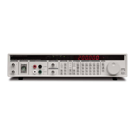
Model DS360
Ultra Low Distortion
Function Generator
DS360 Ultra Low Distortion Function Generator
1290-D Reamwood Avenue
Sunnyvale, CA 94089 U.S.A.
Phone: (408) 744-9040, Fax: (408) 744-9049
email: infor@thinkSRS.com • www.thinkSRS.com
Copyright © 1999 by SRS
All Rights Reserved
Revision 1.9 (3/07)
Advertisement
Chapters
Table of Contents

Related Manuals for Stanford Research Systems DS360


Summary of Contents for Stanford Research Systems DS360
- Page 1 Model DS360 Ultra Low Distortion Function Generator 1290-D Reamwood Avenue Sunnyvale, CA 94089 U.S.A. Phone: (408) 744-9040, Fax: (408) 744-9049 email: infor@thinkSRS.com • www.thinkSRS.com Copyright © 1999 by SRS All Rights Reserved DS360 Ultra Low Distortion Function Generator Revision 1.9 (3/07)
- Page 2 (1) year from the date of shipment. Service For warranty service or repair, this product must be returned to a Stanford Research Systems authorized service facility. Contact Stanford Research Systems or an authorized representative before returning this product for repair.
- Page 3 AC line voltage, or if the wrong fuse is installed. Line Voltage Selection The DS360 operates from a 100, 120, 220 or 240 Vrms AC power source having a line frequency of 50 or 60 Hz. Before connecting the power cord to a power source, verify that the LINE VOLTAGE SELECTOR, located in the rear panel fuse holder, is set so that the correct AC input voltage is visible.
- Page 4 DS360 Ultra Low Distortion Function Generator...
-
Page 5: Table Of Contents
4-18 Hardware Test and Calibration Commands 4-19 Status Byte Definition 4-21 Example Programs 4-23 Chapter 5 Digital Output (Opt. 01) Overview DS360 Digital Functions Setting the Digital Output Inactive Functions and Parameters Default Settings DS360 Ultra Low Distortion Function Generator... - Page 6 Distortion Filter Parts List 7-32 Miscellaneous and Chassis Parts List 7-33 Digital Board Schematics DIG-1 to DIG-7 Analog Board Schematics ANA-1 to ANA-7 Front Panel Schematics FP-1 to FP-2 Programmable Resistor Board Schematics PROGR1 DS360 Ultra Low Distortion Function Generator...
-
Page 7: Table Of Figures
Figure 2-1 Block Diagram Figure 2-2 Front Panel Figure 2-3 Keypad Figure 2-4 Outputs Figure 2-5 Indicators Figure 2-6 Display 2-10 Figure 2-7 Rear Panel 2-12 Figure 2-8 Rear Outputs 2-13 Figure 6-1 Distortion Filter DS360 Ultra Low Distortion Function Generator... - Page 8 Contents DS360 Ultra Low Distortion Function Generator...
-
Page 9: Specifications
25.6 kHz, 51.2 kHz, 102.4 kHz Center Frequency 0 Hz to 200.0 kHz, 200 Hz increments Flatness (in band) < 1.0 dB pk-pk Crest Factor Base Band (0 Hz Center Freq) 12 dB Non Base Band 15 dB DS360 Ultra Low Distortion Function Generator... - Page 10 10 µVpp - 28.8 Vpp 10 µVpp - 40.0 Vpp 600Ω Load 20 µVpp - 80.0 Vpp Hi-Z Load Resolution or V 4 digits or 1µV, whichever is greater dBm or dBV 0.1dB Accuracy +/- 0.1 dB (1%) DS360 Ultra Low Distortion Function Generator...
- Page 11 150 Ω ± 2% 600 Ω ± 1% Hi-Z (50 Ω ± 3%) 50 Ω ± 3% Unbalanced 600 Ω ± 1% Hi-Z (25 Ω ± 1 Ω) Maximum Floating Voltage +/- 40 V DS360 Ultra Low Distortion Function Generator...
- Page 12 GPIB and RS-232 standard. All instrument functions can be controlled over the interfaces. Size 17”W x 3.5”H x 16.25”D Weight 17 lbs. Warranty One year parts and labor on any defects in material or workmanship. DS360 Ultra Low Distortion Function Generator...
-
Page 13: Abridged Command List
Triggers a single sweep or burst. MENA (?) i 4-14 Modify Function Enable (i=1) or Disable (i=0). MTYP (?) i 4-14 Sets the modify function type to Lin Swp, Log Swp, Burst, BWNoise for i=0,1,2,3. DS360 Ultra Low Distortion Function Generator... - Page 14 4-19 Sets the filter mode to n (0,1 or 2). $PRE (?) n 4-19 Sets the DS360 pre-amplifier attenuators to range n (0 to 31). $PST (?) n 4-20 Sets the DS360 post-amplifier attenuators to range n (0 to3). $WRD (?) j,k 4-20 Sets the value of calibration word j to k.
-
Page 15: Chapter 1 Getting Started
Chapter 1 Getting Started These examples are designed to acquaint the first time user with the DS360 Ultra Low Distortion Function Generator. The DS360 is a flexible generator, capable of producing continuous and modified waveforms of exceptionally low noise and distortion, and high frequency accuracy and resolution. The DS360 is also relatively easy to use;... - Page 16 Getting Started DS360 Ultra Low Distortion Function Generator...
-
Page 17: Front Panel Operation
Front Panel Operation Parameters are set in the DS360 using the front panel keypad or the spin knob. Most parameters can be set directly from the keypad, although it is often more convenient to use the spin knob. Keys are referenced by brackets like this: [Key]. -
Page 18: Continuous Waveforms
This places the unit in a known state. 2. Press the [AMPL] key. Press [1][Vpp]. Set the DS360 for a 1 Vpp, 2 kHz sinewave. Press the [FREQ] key. Press [2][kHz]. The oscilloscope should show a 2 kHz sinewave with a 1 Vpp amplitude. -
Page 19: Frequency Sweeps
The DS360 has a TTL sweep signal BNC on the rear panel that marks the beginning of a sweep. Connect the SWEEP OUT BNC on the rear panel of the DS360 to the second channel of the oscilloscope and set it to 2 V/div. The oscilloscope should be set to 0.2 ms/div and to trigger on the rising edge of this signal. -
Page 20: Tone Bursts
They can also be gated from an external source. The DS360 has a TTL burst signal BNC on the rear panel that is high for the duration of the on level of a burst and low otherwise. -
Page 21: Chapter 2 Basics
Traditional Function Generators DS360 Function Generator Front Panel Features Power Switch Reset Spin Knob Keypad Function Output Auxiliary Outputs Indicators Display 2-11 Rear Panel Features 2-12 Power Entry Module 2-12 Auxiliary Outputs 2-13 Computer Interfaces 2-13 DS360 Ultra Low Distortion Function Generator... - Page 22 Basics DS360 Ultra Low Distortion Function Generator...
-
Page 23: Introduction
Basics Introduction to Precision Waveform Synthesis The DS360 uses Direct Digital Synthesis and analog signal processing to generate an extremely pure sinewave with extraordinary frequency resolution and stability. Traditional function generators typically use one of several methods to generate sinewaves, each having one or more major limitations. - Page 24 Basics DDS with Advanced Signal Processing A block diagram for the DS360 is shown in Figure 1. The DS360 utilizes direct digital synthesis to generate its basic waveform. A Motorola DSP56002 advanced 24 bit digital signal processor (DSP) acts as the phase accumulator and contains the internal waveform RAM.
-
Page 25: Front Panel Features
Figure 2-2 Front Panel Power Switch The power for the DS360 is turned on by depressing the power button. After turning the power on the LED display will display the units serial number for about 2 seconds, perform the internal self tests and begin operation. -
Page 26: Figure 2-3 Keypad
Only modify parameters (START FREQ, STOP FREQ ...) that are valid for the selected modify function can be changed. If a currently invalid modify parameter is selected, the unit will beep and display “not APPL” (not applicable). If a function type DS360 Ultra Low Distortion Function Generator... - Page 27 Numeric Keys The numeric keypad allows for direct entry of the DS360’s parameters. To change a parameter value, type the new value, followed by one of the [units] keys. A typing error may be corrected by pressing the [CLR] key, which recalls the old value. The [+/-] key may be selected at any time during numeric entry.
-
Page 28: Figure 2-4 Outputs
A low to high TTL signal on this input begins externally triggered bursts and sweeps. For gated output, a TTL high gates the output on and a TTL low gates the output off. The BNC shield is connected to chassis ground and cannot be floated. DS360 Ultra Low Distortion Function Generator... -
Page 29: Figure 2-5 Indicators
These 4 LEDs indicate the DS360’s status. Status LEDs Name Function The DS360 is in GPIB remote status. The [>] cursor right key returns local control. The DS360 has requested service on the GPIB. Flashes for RS232 or GPIB activity. Flashes on error in a command. - Page 30 Indicates that Amplitude and Frequency Displays refer to TONE 2. Does not indicate a specific display. DEPTH Off Level Depth for Bursts COUNT Burst Count for Bursts TRIGR Trigger Source for Sweeps and Bursts RATE Burst Rate for Bursts DS360 Ultra Low Distortion Function Generator...
-
Page 31: Figure 2-6 Display
Hertz dB relative to preset value Volts Peak-to-Peak Kilohertz dB relative to 1 V into selected source impedance Volts DC % (used with BURST DEPTH) dB relative to 1mW into selected source impedance Vrms DS360 Ultra Low Distortion Function Generator... -
Page 32: Rear Panel Features
The power entry module is used to fuse the AC line, select the line voltage and block high frequency noise from entering or exiting the instrument. The DS360 uses a detachable three wire power cord for connection to the power source and the protective ground. - Page 33 48 kHz. IEEE-488 Connector The 24 pin IEEE-488 connector allows a host computer to control the DS360 via the IEEE-488 (GPIB) instrument bus. The GPIB address of the unit is accessed by pressing [SHIFT][GPIB]. The [>] cursor right key is the instrument “local” key.
- Page 34 This TTL output goes high for the “ON” portion of a burst and low for the “OFF” portion. It can be used to synchronize an external device to a burst. Its shield is connected to chassis ground and cannot be floated. DS360 Ultra Low Distortion Function Generator...
- Page 35 Chapter 3 Operation The following sections describe the operation of the DS360. The first section describes the basics of setting a function, including setting the function type, amplitude, frequency and offset. The second section explains setting the output configuration, including the output type and source impedance. The third section explains sweeps, bursts and bandwidth limited noise.
- Page 36 Operation Troubleshooting 3-21 GPIB Problems 3-21 RS232 Problems 3-21 Error Messages 3-22 Operational Messages 3-23 DS360 Ultra Low Distortion Function Generator...
-
Page 37: Power On
Power On Power On When power is first applied to the DS360 the unit will display its serial number and ROM version. Next the DS360 will initiate a series of self-tests of the internal circuitry and stored data. The test should take about 3 seconds and end with the message “ T EST PASS”... -
Page 38: Setting Functions
To display the current output frequency, press the [FREQ] key. The frequency is displayed in Hz or kHz, depending on which unit LED is lit. The DS360 has 6 digits of frequency resolution or 10 mHz, whichever is greater. Any non displayed digits are zeroed to avoid having slightly different output frequencies for a given display value. -
Page 39: Amplitude
(Hz, kHz). Or change the frequency by using the spin knob. If too high a value is entered, the DS360 will beep and display “ R ange Err” . If a value less than 0.01 Hz is entered, the frequency is set to 0.001 Hz. -
Page 40: Unbalanced Amplitude Ranges
5 µV - 14.40 V 1 µV - 1.800 V -102 - 27.1 -126 - 2.7 5 µV - 14.40 V 2 µV - 5.091 V 2-Tone * -102 - 27.1 -115 - 14.1 DS360 Ultra Low Distortion Function Generator... -
Page 41: Balanced Amplitude Ranges
* The maximum amplitude for 2-Tones is based on the sum of the two signals. Additionally the difference between the two signals is limited to 1000:1 (i.e. the smaller of the two can be no smaller than 1000x less than the larger). DS360 Ultra Low Distortion Function Generator... -
Page 42: Offset
The output may be switched on or off by pressing the [ON/OFF] key. The output status is indicated on the main display under the OUTPUT heading. When the output is off, the output connectors are terminated into the select source impedance. DS360 Ultra Low Distortion Function Generator... -
Page 43: Output Configuration
Operation Output Configuration This section describes how to configure the output type and source impedance of the DS360. Output Type The DS360 has two different output types: unbalanced and balanced. The currently selected output type is indicated by the LED in the OUTPUT section. To change to the other output selection, press [∨] output down key. -
Page 44: Source Impedance
3-10 Operation Source Impedance The source impedance of the DS360 can be set to different values. When the output of the DS360 is terminated into the selected source impedance, the amplitude set on the front panel will be the amplitude seen by the load. If the output is not terminated into the selected load, the amplitude set on the front panel will be incorrect. -
Page 45: Modify Function
Operation 3-11 Modify Function This section describes how to set the modify functions on the DS360, including sweeps, bursts and bandwidth limited noise. Modify Function Type Modify functions are associated with the different output functions. Only the options available for the currently selected function type are accessible in the MODIFY FUNC list. - Page 46 If a non-valid rate is entered, (1.001 kHz for example) the DS360 will round the value down to the nearest legal value. If an out of range value is entered, the DS360 will beep, display “ R ate Err ” and flash the ERR LED. Internal Trigger There are no additional restrictions on internal sweep rates.
-
Page 47: Bursts
Start and Stop Frequencies The DS360 can sweep over any portion of its frequency range, from 0.001 Hz to 200.000 kHz. To display the current start or stop frequency, press the [START] or [STOP] key. To change the start or stop frequency, type a new value using the numeric keypad, followed by the appropriate units (Hz or kHz). - Page 48 The BURST OUT BNC signal, which goes high at the beginning of the burst should be used if it is necessary to synchronize the DS360 with an external device, instead of the triggering signal. This limits the maximum rate that a burst can be triggered externally (or singly) to somewhat less than for internally triggered bursts.
- Page 49 “OFF” level it is necessary to enter an “ON” level and calculate the required attenuation to generate the desired “OFF” level. The burst depth on the DS360 can vary from 0 to 100%, with a 0.1% resolution. It can also be displayed or entered in dB.
-
Page 50: Bandwidth Limited Noise
100 Hz; below 100 Hz will round to 100 Hz. If an out of range value is entered, the DS360 will beep, display “ F req Err ” and flash the ERR LED. - Page 51 (Hz or kHz). If an out of range frequency is entered, the DS360 will beep, display “ F req Err ” and flash the ERR LED.
-
Page 52: Modify Functions
Default Settings Press [RCL][0] to recall the DS360’s default settings. This is a good place to begin whenever you wish to start the instrument from a known state. The default settings are listed below. See Chapter 5 for information on the default settings for the digital output. -
Page 53: Gpib Setup
Pressing [SHIFT][GPIB] a second time will display the last 256 characters of data that has been received by the DS360. This display is a scrollable 3 character window into the DS360’s input data queue. The data is displayed in ASCII hex format, where each character is represented by 2 hexadecimal digits. -
Page 54: Self Tests
3-20 Operation DS360’s input data queue. The data is displayed in ASCII hex format, where each character is represented by 2 hexadecimal digits. The most recently received character is indicated by the decimal point to the right of the digit. Turning the spin knob to the left moves the window earlier into the data queue;... -
Page 55: Troubleshooting
RS-232 Problems Make certain that the baud rate of the controller and the DS360 agree. The baud rate can be set from 300 to 19.2 k; the default is 9600. If it is practical, it is a good idea to use this value. - Page 56 3-22 Operation value.The DS360 is configured to send or receive: 2 stop bits, 8 data bits and no parity bits.When data is being recieved by the DS360, the ACT LED will flash. If this LED is not flashing there is no data being recieved by the DS360.
- Page 57 This message displays an encoded version of the bits 0-3 of the test register (see the *TST command). Other Messages The DS360 displays a number of messages to inform the user of its operational status or of actions the unit has taken. All possible messages are listed below. Operational Messages...
- Page 58 This message is displayed for about 1 second after a SRQ is successfully sent. SRC.INT The Trigger Source for sweeps (int, ext, single) or bursts (int, ext, single, gate). SRC.ETN SRC.SNGL SRC.GATE STEP OFF (/ON) Frequency Step Enable. (Valid for FREQ and 2Tone FREQ). DS360 Ultra Low Distortion Function Generator...
- Page 59 4-12 Frequency Step 4-13 2-Tone Commands 4-13 Number of Bits 4-13 Modify Function Commands 4-14 Trigger 4-14 Modify Function 4-14 Trigger Source 4-14 Sweep Commands 4-14 Burst Commands 4-15 Bandwidth Limited Noise Commands 4-16 DS360 Ultra Low Distortion Function Generator...
- Page 60 System Commands 4-17 Front Panel Commands 4-17 Status Reporting Commands 4-18 Hardware Test & Calibration Commands 4-19 Status Byte Definition 4-21 Example Programs 4-23 GPIB Communications in C 4-24 RS-232 Communications in BASIC 4-25 DS360 Ultra Low Distortion Function Generator...
-
Page 61: Index Of Commands
Sets Sweep Stop Frequency to x. RATE (?) x 4-14 Sets Sweep Rate to x. BCNT (?) x 4-15 Sets Burst Count to x (i=.5, 1-65534). RCNT (?) i 4-15 Sets Burst Rate to x (i=1-65535). DS360 Ultra Low Distortion Function Generator... - Page 62 4-19 Sets the filter mode to n (0,1 or 2). $PRE (?) n 4-19 Sets the DS360 pre-amplifier attenuators to range n (0 to 31). $PST (?) n 4-20 Sets the DS360 post-amplifier attenuators to range n (0 to3). $WRD (?) j,k 4-20 Sets the value of calibration word j to k.
-
Page 63: Introduction
To assist in programming, the DS360 has 4 interface status indicators which are located at the left side of the display. The REM LED is on when the DS360 is in a remote state (front panel locked out). The ACT LED is on whenever data is being received by the DS360. - Page 64 Query the output function. Interface Ready and Status The No Command bit in the Serial Poll Status Byte signals that the DS360 is ready to receive and execute commands. When a command is received, this bit is cleared, indicating that command execution is in process. No other commands will be processed until this command is complete.
- Page 65 GET (Group Execute Trigger) The GPIB command GET will have the same effect as a *TRG command. If the DS360 is configured for a single triggered sweep or burst, then the GET bus command will trigger a sweep or burst. If the DS360 is not configured for one these, the command will be ignored.
-
Page 66: Command Syntax
Parameters shown in { } are not always required. Generally, parameters in { } are required to set a value in the DS360. Multiple parameters are separated by commas. Multiple commands may be sent on one command line by separating them with semicolons (;). -
Page 67: Function Output Commands
2-Tone amplitudes. OFFS (?) x The OFFS command sets the output DC offset to x volts. The OFFS? query returns the current value of the DC offset. For amplitude-offset limits see chapter DS360 Ultra Low Distortion Function Generator... - Page 68 3. If the DS360 must modify the amplitude of either Tone 1 or 2, due to under or over ranging, a message is sent on the front panel and bit 3 in the DDS register is set.
- Page 69 3. If the DS360 must modify the amplitude of either Tone 1 or 2, due to under or over ranging, a message is sent on the front panel and bit 3 in the DDS register is set.
-
Page 70: Digital Output Commands
DIGM (?) i The DIGM command selects the digital output format of the instrument. For i=0 the format is professional and for i=1 it is consumer.The DIGM? query returns the current digital output format. DS360 Ultra Low Distortion Function Generator... - Page 71 10mHz resolution. DTBF(?) x The DTBF command sets the Tone 2 digital frequency to x Hertz. The DTBF? query returns the current Tone 2 frequency. The frequency is set and returned with 10mHz resolution. DS360 Ultra Low Distortion Function Generator...
-
Page 72: Modify Function Commands
FREQ, regardless of what was displayed previously. TSRC (?) i The TSRC command sets the trigger source for bursts and sweeps to i as described in the table below. The TSRC? query returns the current trigger source. DS360 Ultra Low Distortion Function Generator... - Page 73 The NBCT command sets the Noise Burst Count to x. The NBCT? query the Noise Burst Count. The minimum value of x must be within 4 digits of NRCT; the maximum must be less than NRCT (i.e. for NRCT=3s, NBCT ranges from 1ms to 2.999s). DS360 Ultra Low Distortion Function Generator...
- Page 74 The CENF command sets the white noise center frequency to i , which ranges from 0 to 200kHz. The resolution of i is 200 Hz; all settings will be adjusted to i modulo 200. CENF? query returns the currently set value. DS360 Ultra Low Distortion Function Generator...
- Page 75 Setup Control commands *IDN? The *IDN? common query returns the DS360 device identification string. This string is in the format: “StanfordResearchSystems,DS360,sn,vn” where sn is the five digit serial number of the particular unit and vn is a 3 digit firmware version number.
-
Page 76: Status Reporting Commands
The STAT? query reads the value of the DDS status byte. If i is present, the value of bit i is returned (0 or 1). Reading this register will clear it while reading bit i will clear just bit i. DS360 Ultra Low Distortion Function Generator... -
Page 77: Hardware Test And Calibration Commands
Note: The following commands are primarily intended for factory calibration of the DS360 and should never be needed during normal operation. Incorrect use of some of these commands can alter the calibration of the DS360. If this happens, perform a full reset, as described in chapter 3. $FCL The $FCL command recalls the factory calibration bytes. - Page 78 0 to 950, while k may range from - 3270 to 65535. This command will generate an error if the calibration jumper is not enabled. NOTE: This command will alter the calibration of the DS360. To recall the factory calibration, use the $FCL command (Factory Calibration Calbytes). Calibration bytes cannot be altered unless the warm-up bit has been set.
-
Page 79: Status Byte Definition
RQS bit signals that the DS360 is requesting service.The RQS bit will be set to 1 the first time the DS360 is polled following the service request. The serial poll automatically clears the service request. - Page 80 The Warm-up bit will be set and remain set after the warm up period has expired. The rest of the bits in this register are set when the corresponding event occurs and remain set until cleared by reading this status byte (*ESR) or by the *CLS command. DS360 Ultra Low Distortion Function Generator...
-
Page 81: Example Programs
To configure the DS360, the GPIB address must be set in the [SHIFT][GPIB] menu.The default address is 8; use this address unless a conflict occurs with other instruments in your system. The DS360 will be set to GPIB address 8 whenever a reset is performed (power on with the CLR key pressed). - Page 82 /* Setup the DS360 as follows: 50kHz,square wave,1.5Vpp, -1.0Volt offset,display offset */ sprintf (cmd, “FREQ50000”;FUNC1;AMPL1.5VP;OFFS-1.5;KEYS8\n”); ibwrt(ds360,cmd,strlen(cmd)_; /* send command /* Now, query the DS360 for the sweep start and stop frequencies */ sprintf(cmd, “STFR?\n”); /* ask for start freq */ ibwrt(ds360,cmd,strlen(cm)); /* send query ibrd(ds360,start,20);...
- Page 83 Remote Programming 4-25 Example 2: RS232 communication in BASIC language BASIC program to demonstrate communication with the DS360 via RS232. Program assumes the DS360 BAUD rate is set to 9600. 10 OPEN “com2:9600,n,8,2,cs,ds,cd” FOR RANDOM AS #1 ‘ Setup com2’...
- Page 84 4-26 Remote Programming DS360 Ultra Low Distortion Function Generator...
-
Page 85: Chapter 5 Digital Output (Opt. 01)
Digital Output (Opt. 01) The following sections describe the operation of the optional digital output of the DS360. The first section describes the general specifics of the two common digital audio formats, the professional mode (AES-EBU) and the consumer mode (S/PDIF). This is a very basic description of the standards; for further detail the user should obtain the revelant standards. - Page 86 Digital Output DS360 Ultra Low Distortion Function Generator...
-
Page 87: Overview
Digital Output Overview The DS360 is capable of generating digital domain waveforms in two different digital audio formats. The two formats are AES-EBU, the professional digital audio format and S/PDIF, the consumer digital audio format. The following description is provided to help user understand the operation of the DS360’s digital output. -
Page 88: Ds360 Digital Functions
75Ω and a voltage of 0.5 V ±20% into a 75Ω load, with no cable. The connector provided on the DS360 is an RCA phono socket. In addition there is an fiber optic connector (Sharp GP1F32T), compatible with most consumer digital audio fiber optic cables (Sharp GP1C321 type or equivalent). - Page 89 Sample Frequency 0000 = 44.1 kHz, 0010 = 48 kHz, 0011 = 32 kHz (bits 3210) Channel Byte 3, bits 4 - 7 Clock Accuracy 0000 Always Channel Bytes 4 thru 23 Reserved 0 always DS360 Ultra Low Distortion Function Generator...
-
Page 90: Setting The Digital Output
To display the current output frequency, press the [FREQ] key. The frequency is displayed in Hz or kHz, depending on which unit LED is lit. The DS360 has 6 digits of frequency resolution or 10 mHz, whichever is greater. Any non displayed digits are zeroed to avoid having slightly different output frequencies for a given display value. -
Page 91: Amplitude
(Hz, kHz). Or change the frequency by using the spin knob. If too high a value is entered, the DS360 will beep and display “Range Err”. If a value less than 0.01 Hz is entered, the frequency is set to 0.01 Hz. -
Page 92: Inactive Functions And Parameters
Default Settings Press [RCL][0] to recall the DS360’s default settings. This is a good place to begin whenever you wish to start the instrument from a known state. The default settings for the digital output are listed below. - Page 93 44.1 kHz 2-Tone Tone 1 Frequency 1.00000 kHz 2-Tone Tone 2 Frequency 2.00000 kHz 2-Tone Tone 1 Amplitude 50.0 % 2-Tone Tone2 Amplitude 50.0 % Number of Bits GPIB Address RS-232 Baud Rate 9600 DS360 Ultra Low Distortion Function Generator...
- Page 94 5-10 Digital Output DS360 Ultra Low Distortion Function Generator...
- Page 95 3. Frequency Test 4. Amplitude Test 6-10 5. Harmonic Distortion 6-13 6. Waveform Test 6-15 7. Sweep Test 6-17 8. Burst Test 6-18 9. DC Offset Test 6-19 10. Output Impedance 6-21 Performance Record 6-23 DS360 Ultra Low Distortion Function Generator...
- Page 96 Performance Tests DS360 Ultra Low Distortion Function Generator...
-
Page 97: Getting Ready
Getting Ready Parameters are set in the DS360 using the front panel keypad or the spin knob. Most parameters can be set directly from the keypad, although it is often more convenient to use the spin knob. Keys are referenced by brackets like this [KEY]. - Page 98 Test Record Make a copy of the DS360 Performance Test Record at the end of this section. Fill in the results of the tests on this record. The record will allow you to determine whether the unit passes or fails the tests and preserves a record of the tests.
- Page 99 The notch filters described here are used with a spectrum analyzer for verifying the distortion performance of the DS360. Since there are few, if any, spectrum analyzers with a -120 dB distortion floor, a pre-filter is necessary to attenuate the fundamental frequency and increase the sensitivity to distortion signals.
- Page 100 T.H.D. (dB) = 20 log ( (log (2nd)) + (log (3rd)) + (log (4th)) + ... + (log (nth)) where 2nd, 3rd, 4th, ... nth are the values of the corresponding harmonics in dB relative to the fundamental. DS360 Ultra Low Distortion Function Generator...
-
Page 101: Front Panel Test
No external setup is required. Procedure 1) Turn on the DS360 while holding down the [FREQ] key. A single segment of the display should light. 2) Press the [>] to light each segment (of 7) of the left 2 digits and decimal points. Only one segment should be on at a time. - Page 102 No external setup is required. Procedure 1) Turn on the DS360. The ROM firmware version number and the serial number should be displayed for about 3 seconds. The self tests will execute and the message “Tests Pass” should be displayed. If an error message appears, see the TROUBLESHOOTING section in Chapter 3 for a description of the error.
- Page 103 3. Frequency This test measures the frequency accuracy of the DS360. Setup Connect one of the DS360 BNC outputs to the Time Interval Counter. Set the Time Interval Counter to measure frequency with a 1 second gate. Procedure 1) Reset the DS360 (Turn power off, wait 2 seconds, then turn power on w/ [CLR] pressed).
- Page 104 Setup Connect the DS360 + BNC output to the DVM and the scope using a BNC tee. Set the DVM to Vrms, with a long enough integration time to ensure 0.1% accuracy. Connect the DS360 SYNC OUT to the DVM trigger input.
- Page 105 Record the amplitude value from the DVM. 6) The anti-aliaising filter (used for sweeps) accuracy is verified at 1.0 V . To do this, the DS360 is set for an externally triggered sweep, with no triggers provided. This causes the stop frequency to be continuously output, which can be measured.
- Page 106 Press [AMPL][1][V f) Record the amplitude value from the DVM. 9) This completes the amplitude accuracy tests. Enter the results of this test on the test record located at the end of this section. DS360 Ultra Low Distortion Function Generator...
- Page 107 6-5. Procedure 1) Reset the DS360 (Turn power off, wait 2 seconds, then turn power on w/ [CLR] pressed. 2) The distortion is verified at 2 amplitudes and 3 frequencies. Set the spectrum analyzer to exponential vector averaging, with 50 averages and dBV units.
- Page 108 6-14 Performance Tests a) Connect the + output of the DS360 directly to the spectrum analyzers input. Set the spectrum analyzer for a 0 to 12.5 kHz span. b) Press [∨] to select squarewave. [AMPL][1][V c) Measure the amplitudes of the even harmonics (2f, 4f ...) relative to the fundamental. Record the largest even harmonic on the test record.
- Page 109 2-Tone signals. The oscilloscope will be used to measure rise and fall times of the square wave. Connect the + BNC output of the DS360 to the spectrum analyzer. Set the spectrum analyzer input to shield grounded with AC coupling.
- Page 110 Measure the 10% - 90% rise time of the squarewave. Repeat for the fall time. Record the results on the test record. d) Connect the - BNC of the DS360 to the scope CH A and repeat step 5c) for the - channel. 6) This completes the waveform tests.
- Page 111 Connect the + BNC of the DS360 to CH A of the scope. Connect the SWEEP OUT BNC from the rear panel of the DS360 to CH B of the scope. Set CH A to 1 V/div, CH B to 5V/div, the time base to 50µs/div and triggering on CH B.
- Page 112 These tests measures the accuracy of the burst levels. Setup Connect the + BNC output of the DS360 the input of the spectrum analyzer. Set the spectrum analyzer to measure spectrum with the input on AC coupling and the shield grounded. Set averaging to exponential RMS with 10 averages.
- Page 113 These tests measure the offset accuracy of the function of the DS360. Setup Connect the positive output of the DS360 to the DVM. Set the DVM to DC volts, auto-ranging. Perform any auto zeroing functions. Set the integration time long enough for 0.1% accuracy.
- Page 114 [AMPL] [1] [V b) Measure the output voltage on the DVM. Record the results. c) Disconnect the sync signal from the DS360 to the DVM. Set the integration time to the longest possible, to ensure accurate DC measurements of the noise signals.
- Page 115 10. Output Impedance These tests confirms the output source resistors of the DS360. Setup Connect the + BNC output of the DS360 to the DVM through the 50 Ω feed through terminator. Set the DVM to AC volts, auto-ranging. Procedure 1) Reset the DS360 (Turn power off, wait 2 seconds, turn power on w/ [CLR] pressed).
- Page 116 7) Disconnect the + BNC output from the DVM. Connect the - BNC output to the DVM. Repeat steps 1 through 5. 8) Confirm the output on/off function operates a) Press [ON/OFF] (output on/off) b) Confirm that the DVM reads 0 (or nearly zero). 9) This completes the offset tests. DS360 Ultra Low Distortion Function Generator...
-
Page 117: Self Test
20 Hz 0.99 V _______ 1.01 V 50 Hz 0.99 V _______ 1.01 V 100 Hz 0.99 V _______ 1.01 V 200 Hz 0.99 V _______ 1.01 V 500 Hz 0.99 V _______ 1.01 V DS360 Ultra Low Distortion Function Generator... - Page 118 ________ Lower Limit Upper Limit Flatness ________ 101% Noise Amplitude Amplitude Lower Limit Output Upper Limit White Noise 1.00 V 0.99 V _________ 1.01 V Pink Noise 1.00 V 0.99 V _________ 1.01 V DS360 Ultra Low Distortion Function Generator...
- Page 119 Amplitude Upper Limit 100% 19.0 dBV ________ 21.0 dBV 10 % -1.0 dBV ________ +1.0 dBV -21.0 dBV ________ -19.0 dBV 0.1 % -42.0 dBV ________ -38.0 dBV 0.0 % ------ ________ -60 dBV DS360 Ultra Low Distortion Function Generator...
- Page 120 50 Unbal 1.0 V 0.958 V ________ ________ 1.040 V 600 Bal 1.0 V 0.140 V ________ ________ 0.145 V 150 Bal 1.0 V 0.387 V ________ ________ 0.413 V Output On/Off Pass ________ DS360 Ultra Low Distortion Function Generator...
-
Page 121: Overview
Circuit Description Chapter 7 Circuit Description This chapter provides descriptions of the circuitry of the DS360. Each boards description and function is discussed. The schematics and parts list are shown at the end of the chapter. In this Chapter Overview... - Page 122 Circuit Description DS360 Ultra Low Distortion Function Generator...
- Page 123 ROM tables, a 256 word sine table and a 256 word A/Mu Law table (not used in the DS360). There is a single external data bus, which is multiplexed into three sections, X and Y data memory and P program memory. U102, U103 and U104 (32k * 8) make up the DSP memory.
- Page 124 DSP control logic and D/A sync control. This is to avoid any signal contamination due to reflections or load variations. The main clock is divided down by U409 and U410 to provide the different system clocks. DS360 Ultra Low Distortion Function Generator...
- Page 125 D701 and D702 rectify the low AC voltage for the digital section. U701 (LM7805) is a three terminal regulator that provides +5 V for most of the digital circuitry. U702 (LM7805) provides +5 V for the LEDs and displays. U703 (LM317L) provides +7 V for the cooling fan. DS360 Ultra Low Distortion Function Generator...
-
Page 126: Analog Board Description
(2 * F 3 * F ...) without affecting the fundamental signal. Each filter is a second order, state variable, low pass filter. J301 and J302 are connected to switchable resistor networks. DS360 Ultra Low Distortion Function Generator... - Page 127 U503. Q501 and Q502 are active collector loads for U503 A and B. Q507 provides a low impedance source to Q508, which provides most of the voltage gain. It is biased at 3.5 mA by Q509. DS360 Ultra Low Distortion Function Generator...
- Page 128 C741-C749 are bypass capacitors for the +5 V logic (U705). C755-C759 are bypass for the square wave +5 V (U709). C770-C775 are bypass for +28 V. C780-C785 are bypass for -28 V. C776-C777 are bypass for +15 V. C786-C787 are bypass for -15 V. DS360 Ultra Low Distortion Function Generator...
-
Page 129: Front Panel Description
R0-R5. Any combination of resistors can be selected (32 possibilities), however only nine of them are use in the DS360 (R5, R4, R3, R2, R1, R0, R0+R5, R1+R2+R3, R1+R2+R3+R5). Each half of the circuit is always set to the same value. Two of the programmable resistor boards are used in each unit. - Page 130 7-10 Circuit Description DS360 Ultra Low Distortion Function Generator...
-
Page 131: Digital Board Parts List
Capacitor, Ceramic, 50V,+80/-20% Z5U AX C 714 5-00225-548 .1U AXIAL Capacitor, Ceramic, 50V,+80/-20% Z5U AX C 715 5-00225-548 .1U AXIAL Capacitor, Ceramic, 50V,+80/-20% Z5U AX C 716 5-00225-548 .1U AXIAL Capacitor, Ceramic, 50V,+80/-20% Z5U AX DS360 Ultra Low Distortion Function Generator... - Page 132 34 PIN ELH Connector, Male J 601 1-00160-162 IEEE488/STAND. Connector, IEEE488, Standard, R/A, Femal J 602 1-00016-160 RS232 25 PIN D Connector, D-Sub, Right Angle PC, Female J 701 1-00260-116 4 PIN, WHITE Header, Amp, MTA-156 DS360 Ultra Low Distortion Function Generator...
- Page 133 Resistor, Metal Film, 1/8W, 1%, 50PPM R 702 4-00580-407 Resistor, Metal Film, 1/8W, 1%, 50PPM SO402 1-00026-150 28 PIN 600 MIL Socket, THRU-HOLE SP401 6-00096-600 MINI Misc. Components SW701 2-00023-218 DPDT Switch, Panel Mount, Power, Rocker DS360 Ultra Low Distortion Function Generator...
- Page 134 Integrated Circuit (Thru-hole Pkg) U 412 3-00039-340 74HC14 Integrated Circuit (Thru-hole Pkg) U 413 3-00700-343 DS360/U413 GAL/PAL, I.C. U 414 3-00155-340 74HC04 Integrated Circuit (Thru-hole Pkg) U 415 3-00348-340 74HC20 Integrated Circuit (Thru-hole Pkg) DS360 Ultra Low Distortion Function Generator...
- Page 135 U 604 3-00493-340 UPD71051C Integrated Circuit (Thru-hole Pkg) U 605 3-00605-340 MAX202 Integrated Circuit (Thru-hole Pkg) U 703 3-00096-340 LM317L Integrated Circuit (Thru-hole Pkg) UZ409 0-00772-000 1.5" WIRE Hardware, Misc. 0-00089-033 4" 0-00165-003 TO-18 Insulators DS360 Ultra Low Distortion Function Generator...
-
Page 136: Analog Board Parts List
Capacitor, Ceramic, 50V,+80/-20% Z5U AX C 234 5-00225-548 .1U AXIAL Capacitor, Ceramic, 50V,+80/-20% Z5U AX C 235 5-00225-548 .1U AXIAL Capacitor, Ceramic, 50V,+80/-20% Z5U AX C 236 5-00225-548 .1U AXIAL Capacitor, Ceramic, 50V,+80/-20% Z5U AX DS360 Ultra Low Distortion Function Generator... - Page 137 C 338 5-00337-532 Capacitor, Ceramic Disc, 50V, 10% NPO C 339 5-00238-523 Capacitor, Silver Mica, Miniature C 401 5-00215-532 Capacitor, Ceramic Disc, 50V, 10% NPO C 402 5-00215-532 Capacitor, Ceramic Disc, 50V, 10% NPO DS360 Ultra Low Distortion Function Generator...
- Page 138 C 535 5-00238-523 Capacitor, Silver Mica, Miniature C 536 5-00238-523 Capacitor, Silver Mica, Miniature C 701 5-00225-548 .1U AXIAL Capacitor, Ceramic, 50V,+80/-20% Z5U AX C 702 5-00225-548 .1U AXIAL Capacitor, Ceramic, 50V,+80/-20% Z5U AX DS360 Ultra Low Distortion Function Generator...
- Page 139 .1U AXIAL Capacitor, Ceramic, 50V,+80/-20% Z5U AX C 757 5-00023-529 Cap, Monolythic Ceramic, 50V, 20%, Z5U C 758 5-00225-548 .1U AXIAL Capacitor, Ceramic, 50V,+80/-20% Z5U AX C 759 5-00023-529 Cap, Monolythic Ceramic, 50V, 20%, Z5U DS360 Ultra Low Distortion Function Generator...
- Page 140 K 302 3-00523-335 G6AK-234P-ST-UC Relay K 303 3-00617-335 DS1E-ML2-DC5V Relay K 304 3-00523-335 G6AK-234P-ST-UC Relay K 305 3-00523-335 G6AK-234P-ST-UC Relay K 401 3-00523-335 G6AK-234P-ST-UC Relay K 402 3-00523-335 G6AK-234P-ST-UC Relay K 403 3-00523-335 G6AK-234P-ST-UC Relay DS360 Ultra Low Distortion Function Generator...
- Page 141 Q 502 3-00022-325 2N3906 Transistor, TO-92 Package Q 503 3-00021-325 2N3904 Transistor, TO-92 Package Q 504 3-00021-325 2N3904 Transistor, TO-92 Package Q 505 3-00021-325 2N3904 Transistor, TO-92 Package Q 506 3-00022-325 2N3906 Transistor, TO-92 Package DS360 Ultra Low Distortion Function Generator...
- Page 142 Resistor, Metal Film, 1/8W, 1%, 50PPM R 222 4-00479-407 66.5K Resistor, Metal Film, 1/8W, 1%, 50PPM R 223 4-00457-407 33.2K Resistor, Metal Film, 1/8W, 1%, 50PPM R 224 4-00138-407 10.0K Resistor, Metal Film, 1/8W, 1%, 50PPM DS360 Ultra Low Distortion Function Generator...
- Page 143 Resistor, Metal Film, 1/8W, 1%, 50PPM R 415 4-00763-407 14.0K Resistor, Metal Film, 1/8W, 1%, 50PPM R 416 4-00763-407 14.0K Resistor, Metal Film, 1/8W, 1%, 50PPM R 417 4-00176-407 3.01K Resistor, Metal Film, 1/8W, 1%, 50PPM DS360 Ultra Low Distortion Function Generator...
- Page 144 Resistor, Metal Film, 1/8W, 1%, 50PPM R 538 4-00557-407 40.2K Resistor, Metal Film, 1/8W, 1%, 50PPM R 539 4-00416-407 3.24K Resistor, Metal Film, 1/8W, 1%, 50PPM R 540 4-00138-407 10.0K Resistor, Metal Film, 1/8W, 1%, 50PPM DS360 Ultra Low Distortion Function Generator...
- Page 145 Resistor, Metal Film, 1/8W, 1%, 50PPM R 618 4-00490-407 27.4 Resistor, Metal Film, 1/8W, 1%, 50PPM R 619 4-00169-407 Resistor, Metal Film, 1/8W, 1%, 50PPM R 620 4-00883-407 30.9 Resistor, Metal Film, 1/8W, 1%, 50PPM DS360 Ultra Low Distortion Function Generator...
- Page 146 Integrated Circuit (Thru-hole Pkg) U 206 3-00423-340 5534A Integrated Circuit (Thru-hole Pkg) U 207 3-00089-340 LF357 Integrated Circuit (Thru-hole Pkg) U 208 3-00091-340 LF412 Integrated Circuit (Thru-hole Pkg) U 209 3-00211-340 LT1016 Integrated Circuit (Thru-hole Pkg) DS360 Ultra Low Distortion Function Generator...
- Page 147 78L12 Transistor, TO-92 Package U 707 3-00122-325 79L05 Transistor, TO-92 Package U 708 3-00123-325 79L12 Transistor, TO-92 Package 0-00163-007 TO-5 Heat Sinks 0-00165-003 TO-18 Insulators 0-00612-003 TO5 PLASTIC Insulators 0-00772-000 1.5" WIRE Hardware, Misc. DS360 Ultra Low Distortion Function Generator...
-
Page 148: Front Panel Parts List
3-00012-306 GREEN LED, Rectangular D 132 3-00012-306 GREEN LED, Rectangular D 133 3-00012-306 GREEN LED, Rectangular D 134 3-00012-306 GREEN LED, Rectangular D 136 3-00012-306 GREEN LED, Rectangular D 137 3-00012-306 GREEN LED, Rectangular DS360 Ultra Low Distortion Function Generator... - Page 149 Integrated Circuit (Thru-hole Pkg) U 107 3-00288-340 HDSP-H101 Integrated Circuit (Thru-hole Pkg) U 108 3-00288-340 HDSP-H101 Integrated Circuit (Thru-hole Pkg) 0-00011-057 GROMMET Grommet 0-00017-002 TRANSCOVER Power Entry Hardware 0-00025-005 3/8" Lugs 0-00045-013 4-40 MINI Nut, Mini DS360 Ultra Low Distortion Function Generator...
- Page 150 1-00255-100 XLR MALE Connector, Misc. 1-00256-171 8 COND SIL Cable Assembly, Ribbon 1-00257-171 10 COND SIL Cable Assembly, Ribbon 1-00258-171 34 COND DIL Cable Assembly, Ribbon 2-00034-220 ENA1J-B20 SOFTPOT 4-01641-431 YM120, 260V Thermistor, various DS360 Ultra Low Distortion Function Generator...
- Page 151 Lexan Overlay 7-00570-740 DS360-10 Keypad, Conductive Rubber 7-00584-721 DS360-12 Machined Part 7-00646-720 DS360-17 Fabricated Part 7-01256-720 WIRE/PWR SHLD Fabricated Part 9-00267-917 GENERIC Product Labels 9-01516-917 DS360-SERRATO Product Labels 9-01518-917 DS360 - 220V Product Labels DS360 Ultra Low Distortion Function Generator...
-
Page 152: Distortion Filter Parts List
3-00643-360 DG211BDY Integrated Circuit (Surface Mount Pkg) U 3B 3-00643-360 DG211BDY Integrated Circuit (Surface Mount Pkg) U 4A 3-00643-360 DG211BDY Integrated Circuit (Surface Mount Pkg) U 4B 3-00643-360 DG211BDY Integrated Circuit (Surface Mount Pkg) DS360 Ultra Low Distortion Function Generator... -
Page 153: Miscellaneous And Chassis Parts List
Connector, BNC 7-00147-720 BAIL Fabricated Part 7-00562-735 DS360 Injection Molded Plastic 7-00563-720 DS360-3 Fabricated Part 7-00564-720 DS360-4 Fabricated Part 7-00642-720 DS360-13 Fabricated Part 7-00643-720 DS360-14 Fabricated Part 7-00644-720 DS360-15 Fabricated Part 7-00645-720 DS360-16 Fabricated Part DS360 Ultra Low Distortion Function Generator... - Page 154 7-34 Parts List DS360 Ultra Low Distortion Function Generator...
Need help?
Do you have a question about the DS360 and is the answer not in the manual?
Questions and answers