Table of Contents
Advertisement
Quick Links
g
GE Multilin
215 Anderson Avenue
L6E 1B3 Markham, ON -CANADA
T (905) 294 6222 F (905) 294 8512
E gemultilin@ge.com
Internet: www.GEMultilin.com
W650
Wind Generator Protection System
Instruction manual
GEK-113032A
Firmware version: 3.02
EnerVista 650 Setup version: 3.02
Copyright © 2006 GE Multilin
GE Multilin
Avda. Pinoa, 10
48170 Zamudio SPAIN
T +34 94 485 88 00 F +34 94 485 88 45
E gemultilin.euro@ge.com
GE Consumer & Industrial
Multilin
Advertisement
Table of Contents

Related Manuals for GE Multilin W650


Summary of Contents for GE Multilin W650
- Page 1 Multilin W650 Wind Generator Protection System Instruction manual GEK-113032A Firmware version: 3.02 EnerVista 650 Setup version: 3.02 Copyright © 2006 GE Multilin GE Multilin GE Multilin Avda. Pinoa, 10 215 Anderson Avenue 48170 Zamudio SPAIN L6E 1B3 Markham, ON -CANADA...
-
Page 3: Table Of Contents
TABLE OF CONTENTS 1. GETTING STARTED 1.1 IMPORTANT PROCEDURES 1.1.1 CAUTIONS AND WARNINGS ................1-1 1.1.2 INSPECTION CHECKLIST................1-4 1.1.3 SAFETY INSTRUCTIONS ................. 1-6 1.2 OVERVIEW 1.2.1 INTRODUCTION TO 650 FAMILY OF RELAYS ..........1-7 1.2.2 HARDWARE ARCHITECTURE................. 1-7 1.2.3 SOFTWARE ARCHITECTURE ................. - Page 4 TABLE OF CONTENTS 3.5 TRANSCEIVER OPTICAL POWER BUDGET VERSUS LINK LENGTH 4. HUMAN INTERFACES. 4.1 ENERVISTA 650 SETUP SOFTWARE INTERFACE 4.1.1 INTRODUCTION ....................4-1 4.1.2 ENERVISTA 650 SETUP SOFTWARE OVERVIEW .........4-1 4.1.3 MAIN SCREEN....................4-3 4.1.4 COMMUNICATION MENU.................4-4 4.1.5 FILE MANAGEMENT ..................4-6 4.1.6 ENERVISTA 650 SETUP MENUS STRUCTURE ..........4-12 4.1.7...
- Page 5 TABLE OF CONTENTS 5.5 CONTROL ELEMENTS 5.5.1 SETTING GROUP ................... 5-74 5.5.2 UNDERFREQUENCY ELEMENT (81U)............5-75 5.5.3 OVERFREQUENCY ELEMENT (81O) ............5-75 5.5.4 AUTORECLOSE (79) ..................5-76 5.5.5 BREAKER FAILURE ELEMENT (50BF)............5-83 5.5.6 VT FUSE FAILURE ELEMENT (VTFF) ............5-86 5.6 INPUTS/OUTPUTS 5.6.1 INPUT/OUTPUT PLACEMENT ...............
- Page 6 TABLE OF CONTENTS 6.4.4 DATA LOGGER....................6-42 7. IEC 61850 PROTOCOL 7.1 IEC61850 GENERIC SUBSTATION STATE EVENT (GSSE) 7.1.1 REMOTE DEVICES ...................7-1 7.1.2 REMOTE INPUTS ....................7-3 7.1.3 REMOTE OUTPUTS ..................7-4 7.2 IEC 61850 PROFILE FOR W650 7.2.1 INTRODUCTION ....................7-6 7.2.2 ACSI CONFORMANCE STATEMENT...............7-6 7.2.3 LOGICAL NODES ....................7-11 7.2.4...
- Page 7 TABLE OF CONTENTS 11. COMMISSIONING 11.1 VISUAL INSPECTION 11.2 GENERAL CONSIDERATIONS ON THE POWER SUPPLY NETWORK 11.3 ISOLATION TESTS 11.4 INDICATORS 11.5 POWER SUPPLY TESTING 11.6 COMMUNICATIONS 11.7 VERIFICATION OF MEASUREMENT 11.7.1 VOLTAGES ..................... 11-7 11.7.2 PHASE CURRENTS..................11-7 11.7.3 ACTIVE, REACTIVE POWER, AND COSJ METERING .........
- Page 8 TABLE OF CONTENTS 13. FREQUENTLY ASKED 13.1 COMMUNICATIONS QUESTIONS 13.2 PROTECTION 13.3 CONTROL AND HMI 13.4 RELAY CONFIGURATION 14. TROUBLESHOOTING 14.1 SYMPTOMS AND RECOMMENDED ACTIONS GUIDE A. LOGIC OPERANDS A.1 LOGIC OPERANDS B. MODBUS PROTOCOL B.1 ACCESS TO W650 DATA B.2 MODBUS W650 B.2.1 FUNCTIONS USED ...................
- Page 9 D.2 TECHNICAL DESCRIPTION D.3 BASIC APPLICATION FUNCTIONS D.4 IEC 104 SETTINGS D.5 IEC 60870-5-104 POINT LIST E. FACTORY DEFAULT E.1 FACTORY DEFAULT SETTINGS CONFIGURATION E.2 FACTORY DEFAULT CONFIGURATION F. MISCELLANEOUS F.1 GE MULTILIN WARRANTY GEK-113032A W650 Wind Generator Protection System...
- Page 10 TABLE OF CONTENTS VIII W650 Wind Generator Protection System GEK-113032A...
-
Page 11: Getting Started
1 GETTING STARTED 1.1 IMPORTANT PROCEDURES 1 GETTING STARTED 1.1IMPORTANT PROCEDURES 1.1.1 CAUTIONS AND WARNINGS To help ensure years of trouble free operation, please read through the following chapter for information to help guide you through the initial installation procedures of your new relay. BEFORE ATTEMPTING TO INSTALL OR USE THE RELAY, IT IS IMPERATIVE THAT ALL WARNINGS AND CAUTIONS IN THIS MANUAL ARE REVIEWED TO HELP PREVENT PERSONAL INJURY, EQUIPMENT DAMAGE, AND/OR DOWNTIME. - Page 12 Check that the relay is fully operative. Figure 1–2: MODULE WITHDRAWAL/INSERTION GE Multilin will not be responsible for any damage of the relay, connected equipment or personnel whenever these safety rules are not followed.
- Page 13 It is very important, for safety reasons not to change or switch the terminals for CTs and VTs. AC Input Terminals Figure 1–3: REAR VIEW OF W650 UNIT will not be responsible for any damage of the relay, connected equipment or personnel GE Multilin whenever these safety rules are not followed. GEK-113032A W650 Wind Generator Protection System...
-
Page 14: Inspection Checklist
1.1 IMPORTANT PROCEDURES 1 GETTING STARTED 1.1.2 INSPECTION CHECKLIST Unwrap the relay and inspect the relay for physical damage. Verify that the model on the label on the side of the relay matches the model ordered. Figure 1–4: IDENTIFICATION LABEL (A4454P20) Please ensure that you received the following items with your relay: •... - Page 15 1 GETTING STARTED 1.1 IMPORTANT PROCEDURES For product information, instruction manual updates, and the latest software updates, please visit the GE Multilin Home Page www.geindustrial.com/multilin. Note: If there is any physical damage detected on the relay, or any of the contents listed are missing, please...
-
Page 16: Safety Instructions
GE Multilin will not be responsible for any damage to the relay or connected equipment whenever this elemental safety rule is not followed. -
Page 17: Overview
1 GETTING STARTED 1.2 OVERVIEW 1.2OVERVIEW 1.2.1 INTRODUCTION TO 650 FAMILY OF RELAYS Historically, substation protection, control and metering functions were performed with electromechanical equipment. This first generation of equipment was gradually replaced by analog electronic equipment (called static devices), most of which emulated the single-function approach of their electromechanical precursors. - Page 18 1.2 OVERVIEW 1 GETTING STARTED Figure 1–6: 650 CONCEPT BLOCK DIAGRAM Contact Inputs/Outputs are signals associated to the physical input/output contacts in the relay CT and VT inputs are signals coming from the inputs of current and voltage transformers, used for monitoring the power system signals.
-
Page 19: Software Architecture
1 GETTING STARTED 1.2 OVERVIEW 1.2.3 SOFTWARE ARCHITECTURE The firmware (software embedded in the relay) has been designed using object oriented programming techniques (OOP). These techniques are based on the use of objects and classes, and provide the software architecture with the same characteristics as the hardware architecture, i.e., modularity, scalability and flexibility. - Page 20 1.2 OVERVIEW 1 GETTING STARTED Figure 1–7: COMMUNICATIONS ARCHITECTURE (B6816F1) 1-10 W650 Wind Generator Protection System GEK-113032A...
-
Page 21: Enervista 650 Setup Software
1.3.2 INSTALLATION After ensuring the minimum requirements for using EnerVista 650 Setup are met (see previous section), use the following procedure to install the EnerVista 650 Setup from the GE EnerVista CD. Insert the GE EnerVista CD into your CD-ROM drive. - Page 22 1.3 ENERVISTA 650 SETUP SOFTWARE 1 GETTING STARTED In the EnerVista Launch Pad window, click the Add Product button and select the “W650 Wind Generator Protection System” relay from the Install Software window as shown below. Select the “Web” option to ensure the most recent software release, or select “CD”...
- Page 23 1 GETTING STARTED 1.3 ENERVISTA 650 SETUP SOFTWARE EnerVista Launchpad will obtain the installation program from the Web or CD. Once the download is complete, double- click the installation program to install the EnerVista 650 Setup software. Select the complete path, including the new directory name, where the EnerVista 650 Setup will be installed. Click on Next to begin the installation.
- Page 24 1.3 ENERVISTA 650 SETUP SOFTWARE 1 GETTING STARTED 12. The default program group where the application will be added to is shown in the Selected Program Folder window. Click Next to begin the installation process, and all the necessary program files will be copied into the chosen directory. Figure 1–13: SELECT PROGRAM FOLDER 13.
- Page 25 1 GETTING STARTED 1.3 ENERVISTA 650 SETUP SOFTWARE 14. Click Finish to end the installation. The W650 device will be added to the list of installed IEDs in the EnerVista Launchpad window, as shown below. Figure 1–15: ENERVISTA LAUNCHPAD GEK-113032A W650 Wind Generator Protection System 1-15...
-
Page 26: Connecting Enervista 650 Setup Withw650
Before starting, verify that the Ethernet network cable is properly connected to the Ethernet port on the back of the relay. 1. Install and start the latest version of the EnerVista 650 Setup software (available from the GE EnerVista CD or online from http://www.GEindustrial.com/multilin... -
Page 27: W650 Hardware
DB-9 or DB-25 female end is connected to the PC COM1 or COM2 port as described in Figure 1–16:. To communicate through the W650 rear RS485 port from a PC RS232 port, the GE Multilin RS232/RS485 converter box is required. This device (catalog number F485) connects to the computer using a “straight-through” serial cable. A shielded twisted-pair (20, 22 or 24 AWG according to American standards;... -
Page 28: Faceplate Display
1.4 W650 HARDWARE 1 GETTING STARTED Lightning strikes and ground surge currents can cause large momentary voltage differences between remote ends of the communication link. For this reason, surge protection devices are internally provided. To ensure maximum reliability, all equipment should have similar transient protection devices installed. Figure 1–17: RS485 CONNECTION FOR 650 UNITS To comunícate through theW650 rear Ethernet port from a PC a crossover cable is required. -
Page 29: Maintenance
View the event recorder and oscillography or fault report for correct operation of inputs, outputs and elements. If it is concluded that the relay or one of its modules is of concern, contact GE Multilin or one of its representative for prompt service. - Page 30 1.4 W650 HARDWARE 1 GETTING STARTED 1-20 W650 Wind Generator Protection System GEK-113032A...
-
Page 31: Product Description
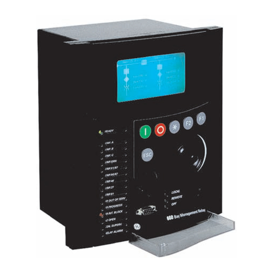
2 PRODUCT DESCRIPTION 2.1 OVERVIEW 2 PRODUCT DESCRIPTION 2.1OVERVIEW 2.1.1 W650 OVERVIEW The modular W650 unit has been designed as a comprehensive generator controller specially adapted to wind turbine generators. Based on the state of the art 650 family, it utilizes modern 32 bit processor platform to provide a complete solution not only for the needs of present systems but also ready for the future. - Page 32 2.1 OVERVIEW 2 PRODUCT DESCRIPTION • Fully programmable front buttons, 15 LED’s and input/output contacts Figure 2–1: FUNCTIONAL BLOCK DIAGRAM W650 Wind Generator Protection System GEK-113032A...
-
Page 33: Summary
2 PRODUCT DESCRIPTION 2.2 SUMMARY 2.2SUMMARY 2.2.1 ANSI DEVICE NUMBERS AND FUNCTIONS DEVICE NUMBER FUNCTION 27P (4) Phase Undervoltage 27X (3) Auxiliary Undervoltage 32 (4) Directional Power 46 (3) Negative Sequence Time Overcurrent 50G (3) Ground Instantaneous Overcurrent (measured from 4 current transformer) 50N (3) Neutral Instantaneous Overcurrent (calculated from the phase currents) - Page 34 2.2 SUMMARY 2 PRODUCT DESCRIPTION OTHER DEVICE FUNCTIONS INPUTS/OUTPUTS METERING COMMUNICATIONS 9 Analog Inputs: 5 current inputs (3 for phases, Metering Current for phases, ground and Front RS232 port, Two rear RS485/ 1 for ground, 1 for sensitive ground), 4 voltage sensitive ground inputs fibre optic ports, 10/100 TX and 100 inputs (3 for phases, 1 for auxiliary voltage)
-
Page 35: Ordering Code
2 PRODUCT DESCRIPTION 2.3 ORDERING CODE 2.3ORDERING CODE W650 units are supplied as ½ 19” rack, 6 units high, containing the following modules: power supply, CPU, I/O modules, communication modules. The required information to completely define an W650 model is shown on Table 2–1: Table 2–1: ORDERING CODE W650 DESCRIPTION... -
Page 36: Technical Specifications
2.4 TECHNICAL SPECIFICATIONS 2 PRODUCT DESCRIPTION 2.4TECHNICAL SPECIFICATIONS NOTE: TECHNICAL SPECIFICATIONS ARE SUBJECT TO CHANGE WITHOUT NOTICE 2.4.1 PROTECTION ELEMENTS Phase and ground units use as operation magnitude the current value received by the unit in current inputs, while the neutral unit uses the calculated current value from the three phase currents. - Page 37 2 PRODUCT DESCRIPTION 2.4 TECHNICAL SPECIFICATIONS Curve Shapes IEEE extremely / very / moderately inverse IEC A/B/C/long-time inverse/short time inverse curve IAC extremely / very / normally / moderately inverse ANSI extremely / very / normally / moderately inverse Definite time Rectifier curve FlexCurve™...
- Page 38 2.4 TECHNICAL SPECIFICATIONS 2 PRODUCT DESCRIPTION 2.4.1.4 SENSITIVE GROUND TIME OVERCURRENT (51SG) Current Input Phasor (without harmonics) or RMS Rated current For connection to 1 or 5 A CTs. Pickup level 0.005 to 16.000 A in steps of 0.001 A Dropout level 98% of the pickup level ±1.5% of the reading ±...
- Page 39 2 PRODUCT DESCRIPTION 2.4 TECHNICAL SPECIFICATIONS 2.4.1.6 NEUTRAL INSTANTANEOUS OVERCURRENT (50N) Current Input Fundamental Phasor (without harmonics) Pickup level 0.05 to 160.00 A in steps of 0.01 A Dropout level 97% of the pickup level ±0.5% of the reading ± 10 mA from 0.05 to 10 A Level Accuracy ±1.5% of the reading for higher values Overreach...
- Page 40 2.4 TECHNICAL SPECIFICATIONS 2 PRODUCT DESCRIPTION 2.4.1.8 NEGATIVE SEQUENCE CURRENT (46) Current Input Fundamental Phasor (without harmonics) Pickup level 0.05 to 160.0 A in steps of 0.01 A Dropout level 98% of the pickup level ±0.5% of the reading ± 10 mA from 0.05 to 10 A Level Accuracy ±1.5% of the reading for higher values Curve Shapes...
- Page 41 2 PRODUCT DESCRIPTION 2.4 TECHNICAL SPECIFICATIONS Characteristic angle -90º to +90º in steps of 1º Block Logic Permission or Block selectable by setting ±2º for I>0.1 A and V>5 Vac Angle accuracy Operate time <30ms, typically 2.4.1.11 NEUTRAL DIRECTIONAL (67N) Directionality Forward and reverse selectable by setting Polarizing...
- Page 42 2.4 TECHNICAL SPECIFICATIONS 2 PRODUCT DESCRIPTION Snapshot Events Selectable by setting 2.4.1.14 PHASE UNDERVOLTAGE (27P) Voltage Input Fundamental Phasor of phase-to-ground or phase-to- phase voltages (selectable by setting) Pickup level 3 to 850 in steps of 1 V Dropout level 103% of the pickup level ±1% reading ±0.1% Full Scale from 10 to 500 V Level accuracy...
- Page 43 2 PRODUCT DESCRIPTION 2.4 TECHNICAL SPECIFICATIONS 2.4.1.17 AUXILIARY UNDERVOLTAGE (27X) Voltage Input Fundamental Phasor Pickup level 3 to 500 V in steps of 1 V Dropout level 97% of the pickup level ±1% reading ±0.1% Full Scale from 10 to 500 V Level accuracy Curve Shapes Fixed time or inverse curve...
-
Page 44: Control
2.4 TECHNICAL SPECIFICATIONS 2 PRODUCT DESCRIPTION Timing accuracy ±3.5% of operate time or 30 ms. (whichever is greater) Block Time after close 0.00 to 900.00 s in steps of 0.01 s Snapshot Events Selectable by setting 2.4.1.21 VOLTAGE UNBALANCE (60V) Pickup level 0.00-500.00% (V2/V1 ratio) in steps of 0.01% Reset delay... -
Page 45: Monitoring
2 PRODUCT DESCRIPTION 2.4 TECHNICAL SPECIFICATIONS ±0.5% of the reading ± 10 mA from 0.05 to 10 A Level Accuracy ±1.5% of the reading for higher values. Timing accuracy ±3.5% of operate time or 30 ms. (whichever is greater) Snapshot Events Selectable by setting 2.4.2.4 BREAKER SETTINGS Number of Switchgear... - Page 46 2.4 TECHNICAL SPECIFICATIONS 2 PRODUCT DESCRIPTION 2.4.3.2 FAULT LOCATOR Method: Single-ended Positive Sequence Module: 0.01 to 250.00 Ohm in steps of 0.01 Ohms Positive Sequence Angle: 25 to 90º in steps of 1º Zero Sequence Module: 0.01 to 750.00 Ohms in steps of 0.01 Ohm Zero Sequence Angle: 25 a 90º...
-
Page 47: User -Programable Elements
2 PRODUCT DESCRIPTION 2.4 TECHNICAL SPECIFICATIONS 2.4.3.5 DEMAND Channels: Parameters: Ia (kA RMS), Ib (kA RMS), Ic (kA RMS), Ig (kA RMS), Isg (kA RMS), I2 (kA), P (MW), Q (MVAr) and S (MVA) Current and Power Method Thermal Exponential, Block Interval, Rolling Demand Measurements: Each channel shows the present and maximum measured value, with date and time for the maximum recorded value. -
Page 48: Metering
2.4 TECHNICAL SPECIFICATIONS 2 PRODUCT DESCRIPTION 2.4.4.3 USER-PROGRAMMABLE LEDS Number: 15 configurable LEDs plus a ready non configurable LED Programmability: from any logical variable, contact, or virtual input Reset mode: Self-reset or Latched. The first 5 LED’s are latched by hardware (red color ones), usually configured for trip signals. -
Page 49: Inputs
2 PRODUCT DESCRIPTION 2.4 TECHNICAL SPECIFICATIONS 2.4.5.5 APPARENT POWER (VA) ±1% of the reading Accuracy: 2.4.5.6 WATT-HOURS (POSITIVE AND NEGATIVE) ±1% of the reading Accuracy: ±0 to 2147 MWh Range: Parameters: 3-phase only Update rate: 100 ms 2.4.5.7 WAR-HOURS (POSITIVE AND NEGATIVE) ±1% of the reading Accuracy: ±0 to 2147 MVArh... - Page 50 2.4 TECHNICAL SPECIFICATIONS 2 PRODUCT DESCRIPTION 2.4.6.2 AC VOLTAGE INPUTS VT Ratio 1.0 to 1500.0 in steps of 0.1 Rated Voltages 500 Vac Metering range: From 2 to 500 Vac Relay Burden: 0.05 VA at 120 Vac (50 or 60 Hz) Voltage Withstand: Continuous at 500 V to neutral 1 min/hr at 800 to neutral...
-
Page 51: Real Time Clock
2 PRODUCT DESCRIPTION 2.4 TECHNICAL SPECIFICATIONS 2.4.6.6 IRIG-B INPUT Amplitude modulation: DC SHIFT = Demodulated input (no carrier) Input Voltage: Input Burden: 1.5 mA Input Impedance: 3.3 kOhm Minimum Input Voltage: 2.4 V Maximum Input Voltage: +/- 24 V Formats: B000 (*) B001, B002 and B003 (*) (*) Signal combinations recognized in accordance with IRIG Standard 200-95 Isolation:... -
Page 52: Control Power Supply
2.4 TECHNICAL SPECIFICATIONS 2 PRODUCT DESCRIPTION 2.4.9 CONTROL POWER SUPPLY LOW RANGE (LO) Nominal DC Voltage: 24 to 48 V Min/Max DC Voltage 19.2 / 57.6 V Note: Low range is DC only HIGH RANGE (HI) Nominal DC Voltage: 110 to 250 V Min/Max DC Voltage 88 / 300 V Nominal AC Voltage:... - Page 53 2 PRODUCT DESCRIPTION 2.4 TECHNICAL SPECIFICATIONS Default Baud Rate 19200 ® Protocols available: ModBus RTU / DNP 3.0 Typical distance: 1200 m Isolation: dc kV1 CAN PORT: Rear port: and cable CAN port in models C and M Fiber CAN port in models X, Y, Z rear board 1 Physical Layer: ISO11898, High speed...
-
Page 54: Optic Features
2.4 TECHNICAL SPECIFICATIONS 2 PRODUCT DESCRIPTION 2.4.11 OPTIC FEATURES Wave length: 1300nm Connector types: ST package style Fiber type: multimode 62.5/125 μm or 50/125 μm TRANSMITTER CHARACTERISTICS Parameter Min. Typ. Max. Unit Reference Output Optical Power dBm avg. Note 1 62.5/125 μm, NA = 0.275 Fiber Output Optical Power -22.5... -
Page 55: Environmental Characteristics
2 PRODUCT DESCRIPTION 2.4 TECHNICAL SPECIFICATIONS 2.4.12 ENVIRONMENTAL CHARACTERISTICS Operating temperature: - 10°C to + 60°C Storage temperature: - 40°C to + 80°C Humidity (non condensing): Altitude Up to 2000 m Installation category 2.4.13 PACKAGING AND WEIGHT Net weight: 5 kg Packaged: 6 kg Package dimensions:... -
Page 56: External Connections
2.5 EXTERNAL CONNECTIONS 2 PRODUCT DESCRIPTION 2.5EXTERNAL CONNECTIONS Figure 2–2: W650 WIRING DIAGRAM (189C4216H12R1) Figure 2–3: 2-26 W650 Wind Generator Protection System GEK-113032A... -
Page 57: Hardware
3 HARDWARE 3.1 MODULE DESCRIPTION MODULE DESCRIPTION 3 HARDWARE 3.1 Digital Optional Power Module Digital Supply SCREEN Figure 3–1: BLOCK DIAGRAM W650 units incorporate the following modules: • Power supply, which can be simple or redundant, depending on the selected model •... -
Page 58: Power Supply
3.2 POWER SUPPLY 3 HARDWARE 3.2POWER SUPPLY W650 can incorporate a simple or redundant power supply. The power supply module is fixed to the base plate using 4 screws, and the main and backup modules are identical. These modules work in parallel continuously, distributing the 50% of the load for each of them, thus ensuring greater reliability, and an instantaneous load transfer from the failed power supply to the other one, without loss of time or module reset. -
Page 59: Mechanical Description
3 HARDWARE 3.3 MECHANICAL DESCRIPTION 3.3MECHANICAL DESCRIPTION The model number and electrical characteristics of the unit are indicated on the label located on the right side of the relay case. The metallic case of the unit is highly resistant to corrosion. It is made of stainless steel (AISI 304), coated with an epoxy layer, and the rest of the metallic pieces are covered with a high quality resistive coating that has successfully passed at least 96 hours in the salt spray chamber (S/N ASTM B-117). - Page 60 3.3 MECHANICAL DESCRIPTION 3 HARDWARE Figure 3–4: DRILLING DIMENSIONS DIAGRAM W650 Wind Generator Protection System GEK-113032A...
-
Page 61: Rear Description
3 HARDWARE 3.3 MECHANICAL DESCRIPTION Figure 3–5: DIMENSIONS OF THE 19” RACKS 6U HIGH FOR TWO RELAYS 3.3.2 REAR DESCRIPTION WARNING Module withdrawal and insertion may only be performed when control power has been removed from the unit. Proper electrostatic discharge protection (i.e. a static wrap) must be used when coming in contact with products while the relay is energized. - Page 62 3.3 MECHANICAL DESCRIPTION 3 HARDWARE Figure 3–6: CONNECTORS LOCATION W650 Wind Generator Protection System GEK-113032A...
- Page 63 3 HARDWARE 3.3 MECHANICAL DESCRIPTION TYPE OF COMMUNICATION CONNECTOR Plug-in, 3 poles. RS485 / CAN cable IRIG B Plug-in, 2 poles. Plastic fiber optic Versatile Link Ethernet 10/100 UTP (10/100BaseTX) RJ45, Class 5. Glass fiber optic (100BaseFX) Ethernet 100 FX (100BaseFX) CAN Fiber Figure 3–7: COMMUNICATIONS MEDIA SELECTOR GUIDE Communication boards are installed at the rear part of the unit, the upper port being reserved for the asynchronous...
- Page 64 3.3 MECHANICAL DESCRIPTION 3 HARDWARE A grounded antistatic wristband must be used when manipulating the module in order to avoid electrostatic discharges that may cause damage to the electronic components. Figure 3–9: REAR TERMINALS LOCATION W650 Wind Generator Protection System GEK-113032A...
-
Page 65: Wiring
3 HARDWARE 3.4 WIRING 3.4WIRING 3.4.1 EXTERNAL CONNECTIONS W650 units can hold different options for F module: Option 1: Board with 16 digital inputs and 8 outputs. Option 2: Board with 8 digital inputs, 4 circuit supervision inputs, 6 conventional outputs, and two current sensing outputs Option 4: Board with 32 digital inputs. - Page 66 3.4 WIRING 3 HARDWARE The default port selected by switch is 10/100 TX in factory configuration. The switch selects between cable (10/100 TX) and the first fiber port (100 FX). In Ethernet board type D (double fiber port) the backup channel is always fiber. Figure 3–10: FIBER/CABLE SELECTION 3-10 W650 Wind Generator Protection System...
- Page 67 3 HARDWARE 3.5 TRANSCEIVER OPTICAL POWER BUDGET VERSUS LINK LENGTH 3.5TRANSCEIVER OPTICAL POWER BUDGET VERSUS LINK LENGTH Optical Power Budget (OPB) is the available optical power for a fiber optic link to accommodate fiber cable losses plus losses due to in-line connectors, splices, optical switches, and to provide margin for link aging and unplanned losses due to cable plant reconfiguration and repair.
- Page 68 3.5 TRANSCEIVER OPTICAL POWER BUDGET VERSUS LINK LENGTH 3 HARDWARE 3-12 W650 Wind Generator Protection System GEK-113032A...
-
Page 69: Human Interfaces
4.1.2 ENERVISTA 650 SETUP SOFTWARE OVERVIEW This software package uses ModBus protocol, and it is designed to communicate with a single relay at a time. GE offers different communication software packages, such as GE-POWER, which can be used to communicate simultaneously with several relays. - Page 70 4.1 ENERVISTA 650 SETUP SOFTWARE INTERFACE 4 HUMAN INTERFACES. 4.1.2.4 VIEWING TRIGGERED EVENTS While the interface is in either on-line or off-line mode, you can view and analyze data generated by triggered specified parameters, via one of the following: • Event Recorder facility: The event recorder captures contextual data associated with the last 479 events, listed in chronological order from most recent to oldest.
-
Page 71: Main Screen
4 HUMAN INTERFACES. 4.1 ENERVISTA 650 SETUP SOFTWARE INTERFACE 4.1.3 MAIN SCREEN The EnerVista 650 Setup software main window supports the following primary display components: • Title bar • Main menu bar • Main icon bar • Working area • Status bar Title Main Menu bar... -
Page 72: Communication Menu
4.1 ENERVISTA 650 SETUP SOFTWARE INTERFACE 4 HUMAN INTERFACES. 4.1.4 COMMUNICATION MENU To start communicating with the relay go to “Communication>Computer>Computer settings” section in the main EnerVista 650 Setup menu. Safety instructions must be followed before connecting the computer to the relay. Safety instructions are detailed in section 1.1.3. - Page 73 4 HUMAN INTERFACES. 4.1 ENERVISTA 650 SETUP SOFTWARE INTERFACE Communication ports: port used in the computer for serial communication. Baud Rate: Baud rate for serial communication (from 1200 up to 115200 bauds in EnerVista 650 Setup, from 300 to 115200 in relay). Parity: parity for serial communication.
-
Page 74: File Management
4.1 ENERVISTA 650 SETUP SOFTWARE INTERFACE 4 HUMAN INTERFACES. 4.1.5 FILE MANAGEMENT File management with EnerVista 650 Setup software: W650 Wind Generator Protection System GEK-113032A... - Page 75 4 HUMAN INTERFACES. 4.1 ENERVISTA 650 SETUP SOFTWARE INTERFACE 4.1.5.1 OFF LINE MODE Run EnerVista 650 Setup Open a *.650 file (“File>Open” menu) Modify protection Settings and relay configuration Is it necessary to program additional logic? Launch the Logic Configuration tool in EnerVista 650 Setup (“Setpoint>Logic Configuration”) Create new or modify the existing logic: (“File>Open Project”)
- Page 76 4.1 ENERVISTA 650 SETUP SOFTWARE INTERFACE 4 HUMAN INTERFACES. Table 4–1: TYPES OF FILES GENERATED BY ENERVISTA 650 SETUP SOFTWARE OPERATION MODE OFF-LINE: LOGIC CONFIGURATION FILES (*.PEP, *AUT, *.LIB) SETTINGS & CONFIGURATION FILE *.650 *.PEP *.AUT *.LIB Graphical edition container. Logic Header for User programmable Description...
- Page 77 4 HUMAN INTERFACES. 4.1 ENERVISTA 650 SETUP SOFTWARE INTERFACE In case of using element libraries (either existing (“File Library>Open Library”) or created by the user (“File Library>New Library”)), the program will create and manage the corresponding files (*.lib) in a folder named FDB (Functional Block Diagram).
- Page 78 4.1 ENERVISTA 650 SETUP SOFTWARE INTERFACE 4 HUMAN INTERFACES. 4.1.5.2 ON LINE MODE Run EnerVista 650 Setup Connect to the relay (“Communication>Computer>ON”) Modify and send to the relay protection Settings and relay configuration Is it necessary to program additional logic? Launch the Logic Configuration tool in EnerVista 650 Setup (“Setpoint>Logic Configuration”) Create new or modify the existing logic...
- Page 79 4 HUMAN INTERFACES. 4.1 ENERVISTA 650 SETUP SOFTWARE INTERFACE Table 4–2: TYPES OF FILES CREATED BY ENERVISTA 650 SETUP– ONLINE OPERATION MODE LOGIC CONFIGURATION FILES (*.PEP, *.AUT, *.LIB) SETTINGS & CONFIGURATION FILE *.650 *.PEP *.AUT *.LIB Graphical edition container. Logic Header for Logic User programmable Description...
-
Page 80: Enervista 650 Setup Menus Structure
4.1 ENERVISTA 650 SETUP SOFTWARE INTERFACE 4 HUMAN INTERFACES. 4.1.6 ENERVISTA 650 SETUP MENUS STRUCTURE The EnerVista 650 Setup menus structure is shown in Table 4–3: . Unless specified, options are available in both On-line and Off-line mode. Options enabled only in On-line mode are marked as (*) Options enabled only in Off-line mode are marked as (**) The “View >... -
Page 81: File Menu Overview
4 HUMAN INTERFACES. 4.1 ENERVISTA 650 SETUP SOFTWARE INTERFACE 4.1.7 FILE MENU OVERVIEW Table 4–4: GENERAL OVERVIEW OF FILE MENU: FILE Open (**) Open a settings and configuration file for off-line working. Save As (**) Save *.650 settings and configuration file. Close (**) Close the opened *.650 file in EnerVista 650 Setup. - Page 82 4.1 ENERVISTA 650 SETUP SOFTWARE INTERFACE 4 HUMAN INTERFACES. 4.1.7.1 OPEN, SAVE AS AND CLOSE In these options, the program opens a dialog box (with default path to Files>Config program folder) where the setting and configuration files can be selected for their “off-line” edition. For enabling access to this menu, there must be no communication between the PC program and the relay.
- Page 83 4 HUMAN INTERFACES. 4.1 ENERVISTA 650 SETUP SOFTWARE INTERFACE 4.1.7.2 CONFIG FILE (*650) CONVERTER Figure 4–6: CONFIG FILE (*650) CONVERTER MENU This tool provides automatic conversion of configuration files from a firmware version to a previous or later version. Open the source *.650 file and select the version and model to be converted to. It is possible to change the model type (FXGX) using the conversion tool.
- Page 84 4.1 ENERVISTA 650 SETUP SOFTWARE INTERFACE 4 HUMAN INTERFACES. 4.1.7.4 PRINTING OPTIONS (PRINT SETUP/PRINT PREVIEW/PRINT/PRINT TO FILE) The printing options are active only in off-line mode, in “File edition”, and not in on-line mode, connected with the relay. a) PRINT SETUP Option to configure the printing options and settings for the printing device.
-
Page 85: Setpoint Menu Overview
4 HUMAN INTERFACES. 4.1 ENERVISTA 650 SETUP SOFTWARE INTERFACE 4.1.8 SETPOINT MENU OVERVIEW Table 4–5: GENERAL OVERVIEW OF SETPOINT MENU IN ENERVISTA 650 SETUP: SETPOINT Communications settings for all protocols and physical mediums. Product Setup ModBus user map definition, fault report, oscillography, data logger and demand settings. - Page 86 4.1 ENERVISTA 650 SETUP SOFTWARE INTERFACE 4 HUMAN INTERFACES. e) COMMUNICATION SETTINGS This section details the settings related to communication parameters for the different protocols available in the W650. Table 4–7: GENERAL OVERVIEW OF COMMUNICATION SETTINGS MENU: COMMUNICATION SETTINGS Serial Ports Baud rate and parity for COM1 and COM2 serial communication ports.
- Page 87 4 HUMAN INTERFACES. 4.1 ENERVISTA 650 SETUP SOFTWARE INTERFACE 4.1.8.3 PROTECTION ELEMENTS This option shows all the protection-grouped elements available in the relay as shown in Table 4–9:. Each of these groups includes the specific protection units of the same type. For example phase currents group includes TOC, IOC, directional units, etc.
- Page 88 4.1 ENERVISTA 650 SETUP SOFTWARE INTERFACE 4 HUMAN INTERFACES. Table 4–10: PROTECTION ELEMENTS INCLUDED PHASE CURRENT Phase TOC High Phase time overcurrent, high level (51PH) Phase TOC Low Phase time overcurrent, low level (51PL) Phase IOC High Phase instantaneous overcurrent, high level (50PH) Phase IOC Low Phase instantaneous overcurrent, low level (50PL) Phase Directional...
- Page 89 4 HUMAN INTERFACES. 4.1 ENERVISTA 650 SETUP SOFTWARE INTERFACE 4.1.8.4 CONTROL ELEMENTS This option shows all the control elements available in the relay as shown in Table 4–11:. Some of the elements are grouped ones such as underfrequency, overfrequency and broken conductor. Table 4–11: GENERAL OVERVIEW OF CONTROL ELEMENTS MENU: CONTROL ELEMENTS...
- Page 90 4.1 ENERVISTA 650 SETUP SOFTWARE INTERFACE 4 HUMAN INTERFACES. 4.1.8.5 INPUT/OUTPUTS Section that contains the settings for all input and output boards and the Force Outputs and Virtual inputs activation tools. Table 4–12: GENERAL OVERVIEW OF “INPUTS/OUTPUTS” SETTINGS MENU. INPUTS/ OUTPUTS Inputs and outputs settings for all boards in W650.
- Page 91 4 HUMAN INTERFACES. 4.1 ENERVISTA 650 SETUP SOFTWARE INTERFACE 4.1.8.6 RELAY CONFIGURATION This is the relay configuration section in which the relay can be configured using internal states or already compiled equation on PLC Editor. Table 4–14: GENERAL OVERVIEW OF RELAY CONFIGURATION MENU: RELAY CONFIG Outputs Configuration of contact output operate and reset signals for all boards.
- Page 92 4.1 ENERVISTA 650 SETUP SOFTWARE INTERFACE 4 HUMAN INTERFACES. The following figures show an example of the default factory configuration for W650. Figure 4–9: RELAY CONFIGURATION Figure 4–10: HMI CONFIGURATION 4-24 W650 Wind Generator Protection System GEK-113032A...
- Page 93 4 HUMAN INTERFACES. 4.1 ENERVISTA 650 SETUP SOFTWARE INTERFACE 4.1.8.7 LOGIC CONFIGURATION This logic configuration allows creating more complex configurations, using the graphical PLC, than using the tables from Relay Configuration. For file management detailed information go to section 4.1.5. File description: *.pep: Header for Logic project: PLC project file containing the necessary information relative to the relay model, logic libraries...
-
Page 94: Actual Values Menu Overview
4.1 ENERVISTA 650 SETUP SOFTWARE INTERFACE 4 HUMAN INTERFACES. 4.1.8.8 CLOCK This menu allows to update the date and time of the relay, either synchronizing them with the PC clock, or entering the information manually. Figure 4–11: CLOCK 4.1.9 ACTUAL VALUES MENU OVERVIEW The menu bar in the main screen of EnerVista 650 Setup software shows the ACTUAL menu option. - Page 95 4 HUMAN INTERFACES. 4.1 ENERVISTA 650 SETUP SOFTWARE INTERFACE Table 4–16: GENERAL OVERVIEW OF STATUS MENU: STATUS Up to 24 elements. OPERATION BIT XX is (0) when the configured time Operation bits out for the operation XX expires or when success conditions are met. And it is (1) if operation XX is executed and interlocks are fulfilled.
- Page 96 4.1 ENERVISTA 650 SETUP SOFTWARE INTERFACE 4 HUMAN INTERFACES. Table 4–18: ACTUAL VALUES INCLUDED IN THE PROTECTION MENU PROTECTION Protection Blocks This screen shows all the protection element blocks available. Protection elements block signals can be configured at “Setpoint>Relay Configuration > Protection Elements”. Phase Current Protection status signals (pickups and operations) for time overcurrent, instantaneous overcurrent and directional protection functions for phase...
- Page 97 4 HUMAN INTERFACES. 4.1 ENERVISTA 650 SETUP SOFTWARE INTERFACE 4.1.9.3 METERING The Metering menu includes all the measurements available in the device. Primary and secondary values, and also the data related to the recording functions in the relay. Table 4–20: GENERAL OVERVIEW OF METERING MENU: METERING Primary Values Primary values measurements for currents, voltages, power, energy and...
-
Page 98: Operations Menu Overview
4.1 ENERVISTA 650 SETUP SOFTWARE INTERFACE 4 HUMAN INTERFACES. 4.1.10 OPERATIONS MENU OVERVIEW Option only available in on line mode, showing all the operations previously configured in the relay with their corresponding texts. Table 4–23: GENERAL OVERVIEW OF OPERATIONS MENU: OPERATIONS Operation 1 (*) Entry to first operation (with its corresponding text) - Page 99 Ethernet communication. Firmware is related to the relay internal program, designed by GE Multilin, which performs the protection and control functions, and which is run by the relay main microprocessor.
- Page 100 4.1 ENERVISTA 650 SETUP SOFTWARE INTERFACE 4 HUMAN INTERFACES. *.pep, *.aut and *.lib files contain the logic configuration projects necessary to modify the logic (virtual outputs) in the relay. These files can be stored in the relay, using the “Communication>Upload info files to relay” option in EnerVista 650 Setup (through Ethernet communication).
-
Page 101: Security Menu Overview
4 HUMAN INTERFACES. 4.1 ENERVISTA 650 SETUP SOFTWARE INTERFACE 4.1.12 SECURITY MENU OVERVIEW The security menu includes all the menus related to security control in EnerVista 650 Setup. EnerVista 650 Setup security users and passwords are not related to passwords in HMI. Each security level has its own access for HMI management and EnerVista 650 Setup management. -
Page 102: Human Machine Interface (Hmi)
4.2 HUMAN MACHINE INTERFACE (HMI) 4 HUMAN INTERFACES. 4.2 HUMAN MACHINE INTERFACE (HMI)T The HMI interface consists of several functional panels. The faceplate can be unscrewed to allow easy access to the removable modules. There is also a removable dust cover that fits over the display and other cover that protects the front RS232 Communications port and the commands buttons that can be sealed. -
Page 103: Front Led Indicators
4 HUMAN INTERFACES. 4.2 HUMAN MACHINE INTERFACE (HMI) 4.2.2 FRONT LED INDICATORS The relay provides 16 LED indicators, 15 user programmable plus one non-configurable LED (READY) that shows if the relay is in service. Programmable LEDs are divided into groups of 5 LEDs, each of the groups having a different color. The first group of LED indicators is latched by hardware (red color ones), usually configured for trip signals. -
Page 104: Front Port And Cover Sealing System
4.2 HUMAN MACHINE INTERFACE (HMI) 4 HUMAN INTERFACES. 4.2.3.2 COMMAND PUSH BUTTON The unit incorporates a command pushbutton located at the bottom right side of the faceplate, with three options: local, remote, and off. The first option (LOCAL) allows executing operations in local mode (HMI, front RS232 port, and rear COM2 port). -
Page 105: Text Menus
4 HUMAN INTERFACES. 4.2 HUMAN MACHINE INTERFACE (HMI) 4.2.5 TEXT MENUS 4.2.5.1 NAVIGATION IN TEXT MENU Text menu is available for all models, this is the main menu for visualizing actual values, metering, changing settings, etc. through the HMI. In models with graphical display (M in ordering code) besides this text main menu there are several screens providing more performance for control purposes. - Page 106 4.2 HUMAN MACHINE INTERFACE (HMI) 4 HUMAN INTERFACES. 4.2.5.2 TEXT MENU HIERARCHY The structure of HMI text menu is similar to the EnerVista 650 Setup in the actual values and settings (view and change) menus. The main menu shows the following options: Table 4–28: GENERAL OVERVIEW OF MAIN TEXT MENU: NAME DESCRIPTION...
- Page 107 4 HUMAN INTERFACES. 4.2 HUMAN MACHINE INTERFACE (HMI) a) ACTUAL VALUES The Actual Values menu option in HMI concentrates and displays all the status of protection, control elements, metering, counters information, oscillography, events, fault locator, etc. Table 4–29: GENERAL OVERVIEW OF ACTUAL VALUES MAIN MENU: Front Panel >...
- Page 108 4.2 HUMAN MACHINE INTERFACE (HMI) 4 HUMAN INTERFACES. Inputs/Outputs > Contact Inputs > Board F/ Board G Cont. Output St. > Board F/ Board G Cont. Output Op. > Board F/ Board G Cont. Output Rs. > Board F/ Board G IO Board Status Virtual Inputs >...
- Page 109 4 HUMAN INTERFACES. 4.2 HUMAN MACHINE INTERFACE (HMI) 4.2.5.3 SNAPSHOT EVENTS To enter this menu press the shuttle key when the option Snapshot events is selected in main menu (). In this menu all the snapshot events stored can be displayed. Snapshot events are changes in the relay internal status.
- Page 110 4.2 HUMAN MACHINE INTERFACE (HMI) 4 HUMAN INTERFACES. Figure 4–19: shows an example of snapshot events navigation: Press shuttle key from the default main screen and enter in the main text menu. Move the shuttle key until a single scroll bar character ( ) appears in the left part of Snapshot event header. Press shuttle key to enter in the snapshot events menu) Select the snapshot event to display using the shuttle key (left and right to move up and down inside the recorded snapshot events).
- Page 111 4 HUMAN INTERFACES. 4.2 HUMAN MACHINE INTERFACE (HMI) Figure 4–19: SNAPSHOT EVENTS NAVIGATION IN HMI GEK-113032A W650 Wind Generator Protection System 4-43...
- Page 112 4.2 HUMAN MACHINE INTERFACE (HMI) 4 HUMAN INTERFACES. 4.2.5.4 FAULT REPORT To enter this menu press the shuttle key when the option Fault report is selected in main menu (). This menu displays information about the last ten faults recorded in the relay. The Relay HMI allows two types of visualization for the fault reports stored in the Relay: 1.
- Page 113 4 HUMAN INTERFACES. 4.2 HUMAN MACHINE INTERFACE (HMI) The format of the displayed screens is as follows: Select the Fault report menu in text menu If there is more than one fault record rotate the shuttle key and select the desired record to be displayed.
- Page 114 4.2 HUMAN MACHINE INTERFACE (HMI) 4 HUMAN INTERFACES. 4.2.5.5 VIEW SETTINGS To enter this menu press the shuttle key when the option “View Settings” is selected in main menu ( ). A secondary level will be displayed with different sublevels as shown on Table 4–30:. Rotating the shuttle key, (left for moving up and right for moving down) select the next level to be displayed ( ), press the shuttle key again to enter in next level and press esc key to return to previous level if desired.
- Page 115 4 HUMAN INTERFACES. 4.2 HUMAN MACHINE INTERFACE (HMI) MAIN SETTINGS MENU FIRST LEVEL SECOND LEVEL THIRD LEVEL Neutral Current > Neutral TOC > Neutral TOC 1 Neutral TOC 2 Neutral TOC 3 Neutral IOC > Neutral IOC 1 Neutral IOC 2 Neutral IOC 3 Neutral Dir >...
- Page 116 4.2 HUMAN MACHINE INTERFACE (HMI) 4 HUMAN INTERFACES. MAIN SETTINGS MENU FIRST LEVEL SECOND LEVEL THIRD LEVEL Phase OV > Phase OV 1 Phase OV 2 Phase OV 3 Neutral OV High > Neutral OV High 1 Neutral OV High 2 Neutral OV High 3 Neutral OV Low >...
- Page 117 4 HUMAN INTERFACES. 4.2 HUMAN MACHINE INTERFACE (HMI) 4.2.5.6 CHANGE SETTINGS To enter this menu press the shuttle key when the option “Change Settings” is selected in main menu. A secondary level will be displayed with different sublevels as shown on Table 4–30:. Rotating the shuttle key, (left for moving up and right for moving down) select the next level to be displayed, press the shuttle key again to enter in next level and press ESC key to return to previous level if desired.
- Page 118 4.2 HUMAN MACHINE INTERFACE (HMI) 4 HUMAN INTERFACES. 4.2.5.7 DATE & TIME The “Date & Time” menu will show the relay date and time information in the following format: Date:Day/Month/Year Time:Hour:Minutes:Seconds To modify date and time, press the shuttle key. The relay will show the year between brackets at the top of the screen. By rotating the shuttle key, reach the desired value for the year, and press the shuttle key to select and store that value.
- Page 119 4 HUMAN INTERFACES. 4.2 HUMAN MACHINE INTERFACE (HMI) 4.2.5.8 COMMANDS Commands are configured using EnerVista 650 Setup, and they can be executed using the pushbuttons on the relay front. Using EnerVista 650 Setup software, the user can configure up to 24 commands with a descriptive text. When executing the operation from the relay front, the operation description text will be displayed.
- Page 120 4.2 HUMAN MACHINE INTERFACE (HMI) 4 HUMAN INTERFACES. 4.2.5.9 PASSWORDS W650 units incorporate independent passwords for protection and control, in order to prevent unauthorized keypad and display access to the relay. Settings Password: This password allows restricting access to settings changes in the relay protection elements. Commands Password: This password is required for executing operation commands through the keypad and display.
- Page 121 Cod Settings: [35c0] Cod Commands: [35c0] <Push Intro> In order to obtain the decoded password from the encrypted codes provided by the relay, it is necessary to contact GE Multilin and provide these encrypted codes. GEK-113032A W650 Wind Generator Protection System...
- Page 122 4.2 HUMAN MACHINE INTERFACE (HMI) 4 HUMAN INTERFACES. 4.2.5.10 SELECT MAIN SCREEN The relay display offers the possibility to select the default main screen. For this purpose, the user must access the “Select Main Screen” menu through the HMI. This menu includes the following options: Logotype This option selects as main screen the relay logotype including the firmware and boot code versions, the relay model and the communication parameters for local port COM2.
-
Page 123: Graphic Display
4 HUMAN INTERFACES. 4.2 HUMAN MACHINE INTERFACE (HMI) 4.2.6 GRAPHIC DISPLAY 4.2.6.1 ONE-LINE DIAGRAM In models with graphic display (W650M) default main screen is the single-line diagram. This single-line diagram can be configured using EnerVista 650 Setup software by choosing the HMI menu inside Relay Configuration (Setpoint>Relay Configuration>HMI). - Page 124 4.2 HUMAN MACHINE INTERFACE (HMI) 4 HUMAN INTERFACES. 4.2.6.2 METERING SCREEN The Metering screen displays relay analog measures in their primary values. Available metering values are as follows: Metering Screen. Total metering 53 Phasor Ia Primary 0.000 KA Phasor Ib Primary 0.000 KA Phasor Ic Primary 0.000 KA...
- Page 125 4 HUMAN INTERFACES. 4.2 HUMAN MACHINE INTERFACE (HMI) 4.2.6.3 ALL EVENTS SCREEN This screen shows all events that have been produced in the relay. The top of the screen shows its name (All Events), and the relative and total number of events contained in the screen. All Events (1/479) This legend means that there are a total of 479 events stored in the relay, and that the cursor is located on event number 1.
- Page 126 4.2 HUMAN MACHINE INTERFACE (HMI) 4 HUMAN INTERFACES. <DETAILS> The Details screen provides access to metering values, and date and time related with the event. The top of the screen displays a legend with the event text, followed by the date and time, the event status (ON or OFF), and the event index number related to the complete list of events in the relay, for example (1/479).
- Page 127 4 HUMAN INTERFACES. 4.2 HUMAN MACHINE INTERFACE (HMI) L-R: Scroll. Rotating the shuttle key left (L) or right (R) moves among all the events contained in the all events screen, allowing a preview of the details for each of them. <AT>...
- Page 128 4.2 HUMAN MACHINE INTERFACE (HMI) 4 HUMAN INTERFACES. 4.2.6.5 ALARMS PANEL Alarms panel can be viewed in all W650 models using communication software EnerVista 650 Setup, however, only models with graphic display allow access to the alarms panel from the HMI. First line shows the relative and total number of alarms existing in that screen.
- Page 129 4 HUMAN INTERFACES. 4.2 HUMAN MACHINE INTERFACE (HMI) <ACK ALL> This option acknowledges all alarms. Alarm acknowledgement through the graphic HMI is considered as through communication port COM2, as it is considered to be Local in both cases. When an alarm has been acknowledged, a selection mark will appear to the right of its status. Inactive alarms will disappear from the screen once they are acknowledged.
- Page 130 4.2 HUMAN MACHINE INTERFACE (HMI) 4 HUMAN INTERFACES. IO Card F. Type: 2, # IN 8, # OUT 8 Input (ON OFF) Output 0 CC1 8 Va COIL1 0 OUT1 1 CC2 9 Vb COIL1 1 OUT2 2 CC3 10 Va COIL2 2 OUT3 3 CC4 11 Vb COIL2...
- Page 131 4 HUMAN INTERFACES. 4.2 HUMAN MACHINE INTERFACE (HMI) Esc: Exit Text. The ESC option returns to the general I/O board menu. Intro: Chg Input. Pressing the shuttle key on the blinking input, this input will be activated in emulation mode. Note: input emulation can only be executed through the TEST INPUT tool on the graphic display.
-
Page 132: Web Server 4.3.1 Home
4.3 WEB SERVER 4 HUMAN INTERFACES. 4.3 WEB SERVER 4.3.1 HOME The web server in the W650 can be accessed running the Windows explorer, and keying http://xxx.xxx.xx.xxx, being xxx.xxx.xxx.xxx the relay IP address, which must be configured in Setpoint > Product Setup > Communication Settings >... -
Page 133: Snapshot Events
4 HUMAN INTERFACES. 4.3 WEB SERVER 4.3.2 SNAPSHOT EVENTS The Snapshot events screen shows all Snapshot events produced in the relay. This screen is refreshed automatically every minute. The information provided in this screen includes: first, the relative event index, the lowest index corresponding to the most recent event;... -
Page 134: Control Events
4.3 WEB SERVER 4 HUMAN INTERFACES. 4.3.3 CONTROL EVENTS The control events screen provides access to all events that have been configured in the Control Events screen inside the Relay Configuration menu of EnerVista 650 Setup. Figure 4–35: CONTROL EVENTS SCREEN Unlike the case of Snapshot events, in this screen the highest index corresponds to the most recent event. -
Page 135: Alarms
4 HUMAN INTERFACES. 4.3 WEB SERVER 4.3.4 ALARMS The alarms screen provides access to alarms configured in the relay. As in the case of snapshot events and control events, this screen allows only to view the alarms, but not to acknowledge them. Figure 4–36: ALARMS SCREEN GEK-113032A W650 Wind Generator Protection System... -
Page 136: Oscillography
Download button. The system will then open a window to allow saving the files in Comtrade format in the PC hard drive. Once the records have been saved, the system will ask if the user wants to open GE-OSC tool (Comtrade record viewer) to view the downloaded files. -
Page 137: Fault Report
4 HUMAN INTERFACES. 4.3 WEB SERVER 4.3.6 FAULT REPORT The fault report screen provides access to the last 10 fault reports obtained by the relay. These records are stored according to an index that marks their position among all records produced in the relay, with a range from 1 to 999, returning to 1 in case of exceeding the limit of 999. -
Page 138: Data Logger
4.3 WEB SERVER 4 HUMAN INTERFACES. 4.3.7 DATA LOGGER The data logger screen allows viewing the data logger first and last value retrieval date and allows downloading the data record files in Comtrade format, by pressing the Download option. Stored files can be viewed later using any Comtrade format viewer. -
Page 139: Metering
4 HUMAN INTERFACES. 4.3 WEB SERVER 4.3.8 METERING This screen includes the 53 primary metering values provided by the relay display. Figure 4–41: METERING SCREEN GEK-113032A W650 Wind Generator Protection System 4-71... - Page 140 4.3 WEB SERVER 4 HUMAN INTERFACES. 4-72 W650 Wind Generator Protection System GEK-113032A...
-
Page 141: Settings
5 SETTINGS 5.1 OVERVIEW 5 SETTINGS 5.1OVERVIEW 5.1.1 SETTING MAIN MENU Table 5–1: GENERAL OVERVIEW OF SETTING MAIN MENU IN ENERVISTA 650 SETUP: Product Setup Communication settings Serial Ports Network (Ethernet) ModBus Protocol DNP3 Slave IEC 870-5-104 CAN Open SNTP ModBus User Map Fault Report Oscillography... - Page 142 5.1 OVERVIEW 5 SETTINGS Voltage Unbalance Power Directional Power Control Elements setting Group Underfrequency Overfrequency Autoreclose Breaker Failure VT Fuse Failure Input/Outputs Contact I/O Board F Board G Force Outputs. Remote Comms. Virtual Inputs Relay configuration Logic configuration Clock W650 Wind Generator Protection System GEK-113032A...
-
Page 143: Product Setup
5 SETTINGS 5.2 PRODUCT SETUP 5.2PRODUCT SETUP 5.2.1 COMMUNICATION SETTINGS 5.2.1.1 SERIAL PORTS Baud rate and parity for COM1 and COM2 serial communication ports. Table 5–2: SERIAL PORTS SETTINGS PRODUCT SETUP > COMMUNICATION SETTINGS >SERIAL PORTS Name Default Value Step Range COM1 Baud Rate 19200... - Page 144 5.2 PRODUCT SETUP 5 SETTINGS 5.2.1.4 DNP3 SLAVE Physical port, Slave Address for DNP, IP Addresses for Masters, TCP/UDP Port, Unsolicited Response parameters, Analog scale factors and deadbands, message fragment size, Binary input block. For more detailed information go to appendix C in this manual.
- Page 145 5 SETTINGS 5.2 PRODUCT SETUP PRODUCT SETUP>COMMUNICATION SETTINGS >DNP3 SLAVE DNP3 SLAVE 1 > DNP3 SLAVE 2 > DNP3 SLAVE 3 Binary Input Block 6 CTL EVENTS 81-96 Binary Input Block 7 CTL EVENTS 97-112 Binary Input Block 8 CTL EVENTS 113-128 Binary Input Block 9 SWITCHGEAR 1-8 Binary Input Block 10...
-
Page 146: Modbus User Map
5.2 PRODUCT SETUP 5 SETTINGS The W650 supports the Simple Network Time Protocol specified in RFC-2030. With SNTP, the W650 can obtain the clock time over an Ethernet network. The W650 acts as an SNTP client to receive time values from an SNTP/NTP server, usually a dedicated product using a GPS receiver to provide an accurate time. -
Page 147: Fault Report
5 SETTINGS 5.2 PRODUCT SETUP 5.2.3 FAULT REPORT 5.2.3.1 OVERVIEW The fault report module defines the type of fault (three-phase, phase-to-phase, phase-to-ground), and the distance to the fault. The fault activation signal (FAULT REPORT TRIGG) is programmed at “Setpoint > Relay Configuration > Protection Elements”. - Page 148 5.2 PRODUCT SETUP 5 SETTINGS 5.2.3.3 FAULT REPORT STATES States associated to the fault report (“Actual >Status>Records Status>Fault Reports”), are shown on Table 5–11: Table 5–11: FAULT REPORT STATES FAULT REPORT STATES FAULT REPORT TRIGG CLEAR FAULT REPORTS FAULT DATE FAULT TYPE FAULT LOCATION FAULT REPORT NUMBER...
-
Page 149: Oscillography
5 SETTINGS 5.2 PRODUCT SETUP 5.2.4 OSCILLOGRAPHY 5.2.4.1 OVERVIEW W650 elements allocate 1-Mbyte of memory for storing oscillography records. These oscillography records are stored in non-volatile memory. Oscillography records are stored in COMTRADE ASCII - IEEE C37.111-1999 standard format. The oscillography module is in charge of storing the instantaneous values of the 9 analog signals and the 16 programmable digital signals at Setpoint >... - Page 150 5.2 PRODUCT SETUP 5 SETTINGS Function Permission (Function): Enabling this setting allows to create an oscillography record when the “TRIGGER OSCILLO” signal is activated. Trigger Position: This setting defines the prefault data (in percentage) stored every time a new oscillo is produced.
- Page 151 5 SETTINGS 5.2 PRODUCT SETUP 5.2.4.3 OSCILLOGRAPHY STATES States associated to the oscillography module (“Actual >Status>Records Status>Oscillography”), are shown in Table 5– Table 5–13: OSCILLOGRAPHY STATES OSCILLOGRAPHY STATES OSC DIG CHANNEL 1 OSC DIG CHANNEL 2 OSC DIG CHANNEL 3 OSC DIG CHANNEL 4 OSC DIG CHANNEL 5 OSC DIG CHANNEL 6...
-
Page 152: Data Logger
Clicking on the “Download” button, the three files (*.DAT, *.HDR, *.CFG) that form the oscillography record in the COMTRADE standard will be retrieved, and they will be viewed automatically if the GE-OSC software is installed in the computer. Retrieved oscillographies can be viewed using any Comtrade viewer. The EnerVista 650 Setup software stores by default oscillography records in the folder “.\EnerVista 650 Setup\files\osc”, in the same directory where the program is... - Page 153 5 SETTINGS 5.2 PRODUCT SETUP 5.2.5.2 DATA LOGGER ASSOCIATED STATES States associated to the data logger module (“Actual >Status>Records Status>”) are shown on the table below: Table 5–15: DATA LOGGER STATES DATA LOGGER STATES OLDEST SAMPLE TIME NEWEST SAMPLE TIME DATA LOGGER CHANNELS DATA LOGGER DAYS OLDEST SAMPLE TIME:...
- Page 154 5.2 PRODUCT SETUP 5 SETTINGS 5.2.6 DEMAND 5.2.6.1 METERING VALUES AND SETTINGS The demand calculation is made according to the following primary parameters: Table 5–16: PRIMARY DEMAND VALUES PRIMARY DEMAND VALUES STEP IA (RMS) IB (RMS) IC (RMS) IG (RMS) ISG (RMS) Three phase active power (W) Three phase reactive power (VAR)
- Page 155 5 SETTINGS 5.2 PRODUCT SETUP Demand module settings are as follows: Table 5–18: DEMAND SETTINGS SETPOINT > PRODUCT SETUP > DEMAND setting Description Name Default Value Step Range Function permission Demand Function DISABLED [DISABLED – ENABLED] Demand method for current values CRNT Demand Method THERMAL EXPONENTIAL [BLOCK INTERVAL - ROLLING DEMAND -...
- Page 156 5.2 PRODUCT SETUP 5 SETTINGS Illustrated bellow is the curve with a 90% characteristic time of 15 minutes. A setting establishes the time to reach 90% of a steady-state value, just as the response time of an analog instrument. A steady-state valve applied for twice the response time will indicate 99% of the value.
- Page 157 5 SETTINGS 5.2 PRODUCT SETUP Figure 5–1: shows the behavior of the demand, depending on the Selected setting for demand calculation. -0,2 Time (minutes) -0,2 Time (minutes) -0,2 Time (minutes) Block interval -0,2 Time (minutes) Rolling demand Figure 5–1: RESPONSE TO THE DIFFERENT DEMAND METHODS GEK-113032A W650 Wind Generator Protection System 5-17...
-
Page 158: Demand Ix
5.2 PRODUCT SETUP 5 SETTINGS 5.2.6.3 DEMAND FUNCTION MEASURES AND STATES Demand values are available at Actual > Metering > Primary Values > Demand. Table 5–19: DEMAND MEASURES NAME DEFAULT VALUE STEP DEMAND IA 0.000 DEMAND IA MAX 0.000 DEMAND IA DATE 01-Jan-2000 00:00:00.000 DEMAND IB 0.000... - Page 159 5 SETTINGS 5.2 PRODUCT SETUP Three-phase active power Three-phase reactive power Three-phase apparent power The maximum demanded value is stored in non-volatile memory. It is not cleared when the relay is turned off. When the relay is turned on again, the maximum values are updated. States associated to the demand (“Actual>Status>Records Status>Demand”) are the following: Table 5–20: DEMAND ASOCIATED VALUES DEMAND ASOCIATED STATES...
-
Page 160: System Setup
5.3 SYSTEM SETUP 5 SETTINGS 5.3SYSTEM SETUP This section shows the settings related to the system setup definition. 5.3.1 GENERAL SETTINGS This section determines the settings of the element configuration regarding its connection to the power system. Access to these settings using the EnerVista 650 Setup software is at Setpoint > System Setup > General settings. The corresponding settings are shown on the table below: Table 5–21: GENERAL SETTINGS SETPOINT >... - Page 161 5 SETTINGS 5.3 SYSTEM SETUP Table 5–22: FLEX CURVE SETTINGS SETPOINT > SYSTEM SETUP > FLEX CURVES FLEX CURVES A > FLEX CURVES B> FLEX CURVES C > FLEX CURVES D setting Description Name Default Value Step Range Values for reset points 0.00 pkp Time 0.00xPKP [RST] 0.000 0.001 s...
-
Page 162: Breaker
5.3 SYSTEM SETUP 5 SETTINGS 5.3.3 BREAKER There are two types of breaker settings: Breaker settings: These settings correspond to the switchgear configured as a breaker in the W650; this switchgear is used in the recloser functions, breaker failure and synchronism. Breaker Maintenance: These settings correspond to the initialization of the (KI) t counters, and the counting of the number of openings and closings of the switchgear configured as a breaker. - Page 163 5 SETTINGS 5.3 SYSTEM SETUP The purpose of this function is to provide closer information of the current status of the breaker’s internal contacts. This is, in order to ensure appropriate breaker maintenance, and to decrease the risk of damage when the breaker has suffered severe operations during a long time.
-
Page 164: Switchgear
5.3 SYSTEM SETUP 5 SETTINGS RESET (KI) t COUNTERS (KI) t Counters reset signal. This signal is configured at Setpoint > Relay Configuration > Protection Elements, and it is used for resetting the (KI) t counter through the corresponding signal, command, digital input, etc. -
Page 165: Protection Elements
5 SETTINGS 5.4 PROTECTION ELEMENTS 5.4PROTECTION ELEMENTS 5.4.1 CHANGE OF SETTING TABLES IN W650 ELEMENTS W650 relays incorporate following protection DIRECTIONAL ELEMENTS elements: 3 x PHASE DIR (67P) CURRENT ELEMENTS 3 x NEUTRAL DIR (67N) Instantaneous overcurrent: 3 x GROUND DIR (67G) 3 x PHASE IOC HIGH (50PH) 3 x SENSITIVE GROUND DIR (67SG) 3 x PHASE IOC LOW (50PL) - Page 166 5.4 PROTECTION ELEMENTS 5 SETTINGS The W650 elements incorporate also the following control elements: 1 x SETTINGS GROUP 4 x OVERFREQUENCY (81O) 4 x UNDERFREQUENCY (81U) 1 x AUTORECLOSE (79) 1 x BREAKER FAILURE (50BF) 1 x FUSE FAILURE (VTFF) W650 elements incorporate a flexible grouping capability for protection ELEMENTS.
- Page 167 5 SETTINGS 5.4 PROTECTION ELEMENTS The distribution of protection elements in tabled groups is described in Table 5–28: Table 5–28: DISTRIBUTION OF PROTECTION ELEMENTS TABLE 1 TABLE 2 TABLE 3 TABLE 4 1x50PH 1x50PH 1x50PH 1x50PL 1x50PL 1x50PL 1x50N 1x50N 1x50N 1x50G 1x50G...
- Page 168 5.4 PROTECTION ELEMENTS 5 SETTINGS GROUP 3 ACT ON This signal produces the activation of setting group 3 GROUP 4 ACT ON This signal produces the activation of setting group 4 These activation signals for the different setting groups are configured using EnerVista 650 Setup at Setpoint > Relay Configuration >...
-
Page 169: Inverse Time Curves Characteristics
5 SETTINGS 5.4 PROTECTION ELEMENTS 5.4.2 INVERSE TIME CURVES CHARACTERISTICS Inverse time curves available in time overcurrent elements are as follows: IEEE extremely/very/moderately inverse IEC Curve A/B/C/Long-Time Inverse/ Short-Time Inverse IAC extremely/very/normally/moderately inverse ANSI extremely/very/normally/moderately inverse Definite time curves Rectifier time curves User Curve - FlexCurve A/B/C/D Recloser Curves The saturation level for the user curve is 20 times the pickup value, for the rest of time overcurrent elements the... - Page 170 5.4 PROTECTION ELEMENTS 5 SETTINGS Table 5–30: CONSTANTS FOR IEEE CURVES IEEE CURVE SHAPE NAME IEEE Extremely Inverse IEEE Ext Inv 28.2 0.1217 2.0000 29.1 IEEE Very Inverse IEEE Very Inv 19.61 0.491 2.0000 21.6 IEEE Inverse IEEE Mod Inv 0.0515 0.1140 0.0200...
- Page 171 5 SETTINGS 5.4 PROTECTION ELEMENTS 5.4.2.2 IEC CURVES This family of curves follows the European standard IEC 255-4, and the British standard BF142 for IEC Curves A, B and C, IEC Long-Time Inverse and IEC Short-Time Inverse. The formulas that define these curves are as follows: Where: t = Operation time in seconds Dial = multiplying factor...
- Page 172 5.4 PROTECTION ELEMENTS 5 SETTINGS Table 5–33: TRIPPING TIME IN SECONDS FOR IEC CURVES DIAL CURRENT (I/ITAP) 10.0 IEC Curve A 0.05 0.860 0.501 0.315 0.249 0.214 0.192 0.176 0.165 0.156 0.149 0.10 1.719 1.003 0.630 0.498 0.428 0.384 0.353 0.330 0.312 0.297...
- Page 173 5 SETTINGS 5.4 PROTECTION ELEMENTS 5.4.2.3 IAC CURVES This family of curves follows the time response of General Electric IAC electromechanical relays. The following formulas define these curves: Where: t = Operation time in seconds Dial = multiplier setting I = Input current Itap = Current pickup value A, B, C, D, E = predefined constants = reset time in seconds...
- Page 174 5.4 PROTECTION ELEMENTS 5 SETTINGS Table 5–35: TRIPPING TIMES IN SECONDS FOR IAC CURVES DIAL CURRENT (I/ITAP) 10.0 IAC Extremely Inverse 1.699 0.749 0.303 0.178 0.123 0.093 0.074 0.062 0.053 0.046 3.398 1.498 0.606 0.356 0.246 0.186 0.149 0.124 0.106 0.093 6.796 2.997...
- Page 175 5 SETTINGS 5.4 PROTECTION ELEMENTS 5.4.2.4 ANSI CURVES This family of curves complies with the American Standard ANSI C37.90 for Extremely inverse, Very inverse, Normally inverse and Moderately inverse curves. The formulas that define these curves are as follows: where: T = Operation time (in seconds).
- Page 176 5.4 PROTECTION ELEMENTS 5 SETTINGS Table 5–37: TRIPPING TIMES IN SECONDS FOR ANSI CURVES DIAL CURRENT (I/ITAP) 10.0 ANSI Extremely inverse 0.50 2.000 0.872 0.330 0.184 0.124 0.093 0.075 0.063 0.055 0.049 1.00 4.001 1.744 0.659 0.368 0.247 0.185 0.149 0.126 0.110 0.098...
- Page 177 5 SETTINGS 5.4 PROTECTION ELEMENTS 5.4.2.5 I2T CURVES The following formulas define this type of curves: where: t = Operation time in seconds Dial = multiplier setting I = Input current Itap = Current pickup value = reset time in seconds RESET Table 5–38: TRIPPING TIME IN SECONDS FOR I2T CURVES DIAL...
- Page 178 5.4 PROTECTION ELEMENTS 5 SETTINGS 5.4.2.8 USER CURVES - FLEXCURVES A/B/C/D The relay incorporates 4 user curves called User Curve A, B, C and D. The points for these curves are defined by the user. Each of the four curves has an operation characteristic (operate), defined by 80 points, and a reset characteristic, defined by 40 points.
-
Page 179: Phase Current
5 SETTINGS 5.4 PROTECTION ELEMENTS 5.4.3 PHASE CURRENT The W650 Phase current menu incorporates the following overcurrent elements: Phase time overcurrent (51PH/51PL) Phase instantaneous overcurrent (50PH/50PL) Phase directional overcurrent (67P) 5.4.3.1 PHASE TIME DELAYED OVERCURRENT ELEMENTS – PHASE HIGH/LOW (51PH/51PL) The phase overcurrent element (51P) operates in a time period that depends on the applied current and on the set curve. - Page 180 5.4 PROTECTION ELEMENTS 5 SETTINGS Table 5–40: PHASE TIME OVERCURRENT SETTINGS SETPOINT > PROTECTION ELEMENTS > PHASE CURRENT > > PHASE TOC HIGH > PHASE TOC HIGH 1> PHASE TOC HIGH 2 > PHASE TOC HIGH 3 > PHASE TOC LOW > PHASE TOC LOW 1 > PHASE TOC LOW 2 > PHASE TOC LOW 3 SETTING DESCRIPTION NAME DEFAULT VALUE...
- Page 181 5 SETTINGS 5.4 PROTECTION ELEMENTS The following diagram shows the logic scheme followed by high range and low range time overcurrent elements (51PH and 51PL) in the following figure. Figure 5–5: TOC ELEMENT LOGIC SCHEME (A6632F2) GEK-113032A W650 Wind Generator Protection System 5-41...
- Page 182 5.4 PROTECTION ELEMENTS 5 SETTINGS 5.4.3.2 PHASE INSTANTANEOUS OVERCURRENT ELEMENT- PHASE HIGH/LOW (50PH/ 50PL) The Phase instantaneous overcurrent element has a setting range from 0.05 A to 160 A. It can be set as instantaneous or timed, with the timer selectable between 0.00 and 900 seconds. The input quantities may be chosen as Fundamental phasor magnitude or RMS magnitude as required by the application.
- Page 183 5 SETTINGS 5.4 PROTECTION ELEMENTS The following figure shows the logic scheme diagram for high range and low range Instantaneous overcurrent elements (50PH, 50PL). Figure 5–6: PHASE IOC ELEMENTS LOGIC SCHEME (A6632F1) GEK-113032A W650 Wind Generator Protection System 5-43...
- Page 184 5.4 PROTECTION ELEMENTS 5 SETTINGS 5.4.3.3 PHASE DIRECTIONAL ELEMENT (67P) The Phase directional element (67P) provides independent elements for each phase, and determines the direction of the current both in permanence and in fault condition. Its main function is to apply a blocking signal to the overcurrent elements to prevent their operation when the current is flowing in a certain direction.
- Page 185 5 SETTINGS 5.4 PROTECTION ELEMENTS Table 5–43: BLOCK AND OPERATION SIGNALS FOR THE PHASE DIRECTIONAL ELEMENT BLOCK AND OPERATION FOR 67P PHASE DIR1 BLOCK A PHASE DIR1 A OP PHASE DIR1 BLOCK B PHASE DIR1 B OP PHASE DIR1 BLOCK C PHASE DIR1 C OP PHASE DIR2 BLOCK A PHASE DIR2 A OP...
- Page 186 5.4 PROTECTION ELEMENTS 5 SETTINGS Figure 5–7: OVERCURRENT ELEMENTS BLOCK CONFIGURATION BY THE DIRECTIONAL ELEMENT Directional elements can also be blocked with signals coming from other relays, PLCs, or through signals configured in the relay PLC Editor (Logic configuration tool). The signal used in that case is PHASE DIR BLK INP. Figure 5–8: shows an example of the default block configuration of directional elements by digital input.
- Page 187 5 SETTINGS 5.4 PROTECTION ELEMENTS The polarization diagram is as follows: Figure 5–9: POLARIZATION DIAGRAM The diagram shows a fault in phase A, therefore the Operation magnitude is IA, the polarization magnitude is VBC, which has been rotated the torque angle set as MTA. Positive angles are considered as counter clockwise rotations, and negative angles clockwise rotations.
- Page 188 5.4 PROTECTION ELEMENTS 5 SETTINGS The following figure shows the logic scheme for the phase directional element. Figure 5–10: DIRECTIONAL ELEMENT LOGIC SCHEME (A6632F3) 5-48 W650 Wind Generator Protection System GEK-113032A...
- Page 189 5 SETTINGS 5.4 PROTECTION ELEMENTS 5.4.4 NEUTRAL CURRENT The Neutral Current menu incorporates the following overcurrent elements: • Neutral time overcurrent (51N) • Neutral instantaneous overcurrent (50N) • Neutral directional element (67N) 5.4.4.1 NEUTRAL TIME DELAYED OVERCURRENT ELEMENT (51N) Neutral TOC is a neutral time delayed overcurrent protection element. This element uses as the input quantity the neutral current, calculated from the phase currents.
- Page 190 5.4 PROTECTION ELEMENTS 5 SETTINGS The following figure shows the logic scheme for the neutral Instantaneous overcurrent element. Figure 5–11: LOGIC SCHEME FOR NEUTRAL IOC ELEMENT 5-50 W650 Wind Generator Protection System GEK-113032A...
- Page 191 5 SETTINGS 5.4 PROTECTION ELEMENTS 5.4.4.3 NEUTRAL DIRECTIONAL ELEMENT (67N) The Neutral directional element is used for supervising the neutral (3I0) overcurrent elements. This element can be set to use either the neutral voltage, or the polarization current measured by the 5 current input (Ip), or both as polarization magnitude.
-
Page 192: Neutral Current
5.4 PROTECTION ELEMENTS 5 SETTINGS The Neutral directional element is an independent Protection element that provides Block and Operation signals. These signals can be monitored both through the relay HMI or using EnerVista 650 Setup at “Actual > Status > Protection > Neutral Current”... - Page 193 5 SETTINGS 5.4 PROTECTION ELEMENTS Figure 5–12: shows the Operation of the directional element for a Phase A to Ground fault, where the Phase A current grows in magnitude and is delayed with respect to its voltage by an angle similar to the protected line. Va voltage decreases or can even disappear if the fault is close and the fault resistance is very low.
- Page 194 5.4 PROTECTION ELEMENTS 5 SETTINGS b) CURRENT POLARIZATION OPERATION PRINCIPLES: Operation Magnitude: In = calculated from phase currents. Polarization Magnitude: Ip, measured at input terminals B11-B12. To perform a directional comparison by current, the polarization magnitude used is the current measured at the relay Ip input, terminals B11-B12, with input or “positive”...
- Page 195 5 SETTINGS 5.4 PROTECTION ELEMENTS Table 5–50: QUANTITIES POLARIZING MODE DIRECTION COMPARED PHASORS FORWARD Io x 1 MTA VOLTAGE (Vo) REVERSE -Io x 1 MTA FORWARD CURRENT (Ip) REVERSE - Vo FORWARD Vo + Ip - Vo REVERSE - Vo FORWARD Vo * Ip - Vo...
-
Page 196: Ground Current
5.4 PROTECTION ELEMENTS 5 SETTINGS 5.4.5 GROUND CURRENT The Ground Current menu incorporates the following overcurrent elements: Ground time overcurrent (51G) Ground instantaneous overcurrent (50G) Ground directional element (67G) 5.4.5.1 GROUND TIME DELAYED OVERCURRENT ELEMENT (51G) Ground TOC is a ground time delayed overcurrent protection element. The ground current is measured from the ground input, terminals B9-B10, and it may be programmed as Fundamental phasor magnitude or RMS magnitude as required by the application. - Page 197 5 SETTINGS 5.4 PROTECTION ELEMENTS 5.4.5.3 GROUND DIRECTIONAL ELEMENT (67G) Ground directional is a directional protection element, used for monitoring the ground overcurrent elements. The operation magnitude is the ground current measured directly from the corresponding input (B9-B10), while the polarization magnitude is the neutral voltage (V ).
- Page 198 5.4 PROTECTION ELEMENTS 5 SETTINGS The following table shows the management of the element output signals (block and permission) depending on the Polarization Type setting. Table 5–55: OUTPUT SIGNALS MANAGEMENT ACCORDING TO THE POLARIZTION TYPE SETTING POLARIZATION SETTING GROUND DIR BLOCK SIGNAL GROUND DIR OP SIGNAL <...
-
Page 199: Sensitive Ground Current
5 SETTINGS 5.4 PROTECTION ELEMENTS 5.4.6 SENSITIVE GROUND CURRENT The W650 Sensitive ground Current menu incorporates the following overcurrent elements: • Sensitive ground time overcurrent (51SG) • Sensitive ground instantaneous overcurrent (50SG) • Sensitive ground directional overcurrent (67SG) 5.4.6.1 SENSITIVE GROUND TIME DELAYED OVERCURRENT ELEMENT (51SG) Sensitive Ground TOC is a sensitive ground time delayed overcurrent protection element with a setting range 0.005A to 16A. - Page 200 5.4 PROTECTION ELEMENTS 5 SETTINGS 5.4.6.3 SENSITIVE GROUND DIRECTIONAL ELEMENT (67SG) Sensitive Ground directional is a directional element used for supervising sensitive ground overcurrent functions. The operation magnitude is the ground current measured directly from the corresponding input (terminals B11-B12), while the polarization magnitude is the neutral voltage (3Vo).
- Page 201 5 SETTINGS 5.4 PROTECTION ELEMENTS 67SG Block (SENS GND DIR1 BLOCK): It indicates that the element is blocked by digital input or because the Operation magnitude (In current), or the Polarization magnitude (Vn voltage and/or Ip current) level is too low. 67SG Operation (SENS GND DIR1 OP): It indicates that the directional element is giving permission, the operation magnitude and the polarization magnitude conditions are met, or in case of having selected Permission in the Block Logic setting, it indicates that the element allows operation under block conditions.
-
Page 202: Negative Sequence Current
5.4 PROTECTION ELEMENTS 5 SETTINGS 5.4.7 NEGATIVE SEQUENCE CURRENT The Negative sequence menu incorporates the Negative sequence time overcurrent (46P) element: 5.4.7.1 NEGATIVE SEQUENCE OVERCURRENT ELEMENT (46P) Negative Sequence TOC is an overcurrent protection element that uses the fundamental phasor of the negative sequence current as input magnitude, calculated from the phase currents. -
Page 203: Voltage Elements
5 SETTINGS 5.4 PROTECTION ELEMENTS 5.4.8 VOLTAGE ELEMENTS The W650 incorporates the following voltage elements: • Phase undervoltage (27P) • Phase overvoltage (59P) • Neutral overvoltage (59NH/59NL) • Auxiliary overvoltage (59X) • Auxiliary undervoltage (27X) • Voltage Unbalance (60) These protection elements can be used in multiple applications, such as: Undervoltage protection: for induction motor load types, where a voltage dip can cause an increase of the consumed current. - Page 204 5.4 PROTECTION ELEMENTS 5 SETTINGS 5.4.8.1 PHASE UNDERVOLTAGE ELEMENT (27P) This element may be used to give a desired time-delayed operating characteristic versus the applied fundamental voltage (phase-to-ground or phase-to-phase for wye VT connection, or phase-to phase- for Delta VT connection) or as a Definite time element.
- Page 205 5 SETTINGS 5.4 PROTECTION ELEMENTS 5.4.8.2 PHASE OVERVOLTAGE ELEMENT (59P) The Phase overvoltage element may be used as an instantaneous element with no intentional time delay or as a Definite Time element. The input voltage is the phase-to-phase voltage, either measured directly from Delta-connected VTs or as calculated from phase-to-ground (wye) connected VTs.
- Page 206 5.4 PROTECTION ELEMENTS 5 SETTINGS 5.4.8.3 NEUTRAL OVERVOLTAGE ELEMENT (HIGH LEVEL AND LOW LEVEL) (59NH/59NL) The Neutral Overvoltage element can be used to detect an asymmetrical system voltage condition due to a ground fault or to the loss of one or two phases of the source. The element responds to the system neutral voltage (3V0), calculated from the phase voltages or measured by the 4th voltage transformer.
- Page 207 5 SETTINGS 5.4 PROTECTION ELEMENTS 5.4.8.5 AUXILIARY UNDERVOLTAGE ELEMENT (27X) This is an Auxiliary undervoltage element for general use that uses as its input magnitude the voltage measured by the 4 VT, terminals A11-A12. Table 5–65: 27X ELEMENT SETTINGS SETPOINT > PROTECTION ELEMENTS > VOLTAGE ELEMENTS > AUXILIARY UV > AUXILIARY UV 1>...
-
Page 208: Power
5.4 PROTECTION ELEMENTS 5 SETTINGS 5.4.9 POWER 5.4.9.1 DIRECTIONAL POWER ELEMENT (32) a) ELEMENT DESCRIPTION The Directional Power element responds to three-phase active power measured from the feeder associated to the W650. This element can be selected to operate according to the power threshold adjusted in the corresponding setting. This element is ideal for reverse power applications (F32 REV) or forward power (F32 FWD), depending on the selected setting. - Page 209 5 SETTINGS 5.4 PROTECTION ELEMENTS Figures (a, b, c, d, e, f) below shows settings for different power applications. Figure 5–15: DIRECTIONAL POWER ELEMENT SAMPLE APPLICATIONS By adding 90º to the angles shown on figures a, b, c and d, the represented elements would be similar but with Reactive Power instead of Active Power.
- Page 210 5.4 PROTECTION ELEMENTS 5 SETTINGS A different angle selection for Stage 1 and Stage 2 could provide in a single element, a Reactive and Active power limitation. For example, using the following values: Dir Power Angle 1(RCA) 0º Stage 1 Tap Dir Power Angle 2(RCA) 90º...
- Page 211 5 SETTINGS 5.4 PROTECTION ELEMENTS The following figure illustrates the conventions established: Figure 5–16: ANGLES GEK-113032A W650 Wind Generator Protection System 5-71...
- Page 212 5.4 PROTECTION ELEMENTS 5 SETTINGS Stage (1 - 2) Tap: This setting specifies the minimum Operation three-phase power for the Stage 1 (2) element. The power value defined in this setting is the minimum distance between the source and the directional power characteristic. This value can be positive or negative.
- Page 213 5 SETTINGS 5.4 PROTECTION ELEMENTS c) STATUSES Statuses defined for this Function are as follows: DIR PWR1 (2, 3, 4) BLOCK : Writing status, operates by level. When this status is activated externally (via PLC), the directional power element is blocked. This status affects both elements in the protection element (stage 1 and 2).
-
Page 214: Control Elements
5.5 CONTROL ELEMENTS 5 SETTINGS 5.5CONTROL ELEMENTS The W650 incorporates the following control elements: Setting Group Underfrequency Overfrequency Autoreclose (79) Breaker Failure (50BF) VT Fuse Failure Note: for all control elements related to the breaker, it must be considered that all operations will be performed considering the status of the switchgear configured as breaker. -
Page 215: Underfrequency Element (81U)
5 SETTINGS 5.5 CONTROL ELEMENTS 5.5.2 UNDERFREQUENCY ELEMENT (81U) Setpoint >Control Elements > Underfrequency The steady-state frequency of a power system is a certain indicator of the existing balance between the generated power and the load. Whenever this balance is disrupted through the loss of an important generating unit, the effect will be a reduction in frequency. -
Page 216: Autoreclose (79)
5.5 CONTROL ELEMENTS 5 SETTINGS 5.5.4 AUTORECLOSE (79) 5.5.4.1 INTRODUCTION Note: The Switchgear element used in the W650 autoreclose element is the one configured in the Number of Switchgear setting inside Breaker settings, at “Setpoint > System Setup > Breaker > Breaker settings”. Configuration of these Switchgear parameters is performed at Setpoint >... - Page 217 5 SETTINGS 5.5 CONTROL ELEMENTS 5.5.4.3 AUTORECLOSE INPUTS For the correct operation of the autoreclose element, it is required to configure several input signals in the Relay. These signals can be configured using the EnerVista 650 Setup software, at Setpoint > Relay Configuration > Protection Elements.
- Page 218 5.5 CONTROL ELEMENTS 5 SETTINGS 5.5.4.4 AUTORECLOSE INTERNAL STATUS Actual> Status > Control Elements > Autoreclose. These signals can be used as conditions for executing logics in the relay; they are also useful to know the autoreclose behavior. Table 5–73: 79 INTERNAL STATUS AUTORECLOSE SINGLE STATUS AUTORECLOSE ENUMERATED STATUS AR CLOSE BREAKER...
- Page 219 5 SETTINGS 5.5 CONTROL ELEMENTS AR BLOCK BY PULSE Autoreclose blocked by pulse. See AR block signals configuration (AR PULSE BLOCK) AR STATUS Autoreclose status (see Table 5–73:) AR LOCKOUT MODE Autoreclose lockout mode (see Table 5–73: ) AR BLOCK MODE Autoreclose block mode (see Table 5–73:) GEK-113032A W650 Wind Generator Protection System...
- Page 220 5.5 CONTROL ELEMENTS 5 SETTINGS 5.5.4.5 GENERAL AUTORECLOSE STATUS DIAGRAM The following diagram describes the different autoreclose states, as well as the transitions between states. Figure 5–17: GENERAL AUTORECLOSE STATUS DIAGRAM Description of the general autoreclose status: OUT OF SERVICE / AR DISABLE In this status, the autoreclose is disabled.
- Page 221 5 SETTINGS 5.5 CONTROL ELEMENTS Once the breaker is open, it waits for the time set in the Dead Time N setting, N being the number of the cycle in progress. If during this waiting the breaker is closed or reclose initiation conditions are given, the recloser will go to LOCKOUT status by anomaly (AR LCK BY ANOMALY).
- Page 222 5.5 CONTROL ELEMENTS 5 SETTINGS 5.5.4.6 LOGIC FOR BLOCKING PROTECTION FUNCTIONS DURING THE RECLOSING CYCLE The W650 autoreclose generates a series of internal signals that allow performing block logics for Protection elements during the reclosing cycle. These signals are blocks after autoreclose shots (BLK AFTER SHOT). For example, if the user wants to block a protection element during the complete reclosing cycle, it is necessary to configure a signal as an OR of the four blocking signals provided after each reclosing cycle in the logic configuration tool Setpoint >...
-
Page 223: Breaker Failure Element (50Bf)
5 SETTINGS 5.5 CONTROL ELEMENTS 5.5.5 BREAKER FAILURE ELEMENT (50BF) Note: The Switchgear element used in the Breaker Failure element is the one configured in the Number of Switchgear setting, inside Breaker settings at Setpoint > Protection Elements > Breaker > Breaker settings The breaker failure element is used to determine when a trip command sent to a breaker has not been executed within a selectable delay. - Page 224 5.5 CONTROL ELEMENTS 5 SETTINGS Signals relative to breaker failure provided by the relay can be viewed at Actual> Status > Control Elements > Breaker Failure, and they are as follows: Table 5–75: BREAKER FAILURE STATUS BREAKER FAILURE STATUS BKR FAIL INITIATE BKR FAIL NO CURRENT BKR FAIL SUPERVISION BKR FAIL HISET...
- Page 225 5 SETTINGS 5.5 CONTROL ELEMENTS The following figure shows the logic scheme for the breaker failure element: Figure 5–20: LOGIC SCHEME FOR 50BF The breaker failure element has three levels. The first one is called “Retrip” or “Supervision”. This operation level can be used to give a signal to the breaker on which the initial opening has been executed.
-
Page 226: Vt Fuse Failure Element (Vtff)
5.5 CONTROL ELEMENTS 5 SETTINGS 5.5.6 VT FUSE FAILURE ELEMENT (VTFF) Note: The Switchgear element used in the VT Fuse Failure element is the one configured in the Number of Switchgear setting, inside Breaker settings at Setpoint > Protection Elements > Breaker > Breaker settings. This switchgear must have previously been configured at Setpoint >... - Page 227 5 SETTINGS 5.5 CONTROL ELEMENTS Figure 5–21: FUSE FAILURE ELEMENT BLOCK DIAGRAM GEK-113032A W650 Wind Generator Protection System 5-87...
-
Page 228: Inputs/Outputs
5.6 INPUTS/OUTPUTS 5 SETTINGS 5.6INPUTS/OUTPUTS 5.6.1 INPUT/OUTPUT PLACEMENT MIXED SUPERVISION INPUTS ANALOG TERMINALS COIL 1 CC1 52/a CC2 COIL 1 CC3 52/b CC4 COMMON 1/8 COMMON 1/4 COMMON 1/8 COMMON 1/8 COMMON 9/16 COMMON 5/8 COMMON 9/16 COMMON 9/16 CC10 CC10 CC10 CC11... -
Page 229: Control Settings For Inputs/Outputs
5 SETTINGS 5.6 INPUTS/OUTPUTS 5.6.2 CONTROL SETTINGS FOR INPUTS/OUTPUTS Configuration of settings relative to inputs and outputs can only be accessed through the EnerVista 650 Setup software, and not via the HMI. For this purpose, the user must access Setpoint > Inputs/Outputs > Contact I/O > Board X, being X the corresponding I/O board. - Page 230 5.6 INPUTS/OUTPUTS 5 SETTINGS For the I/O board selection in the relay model, associated digits to each board type are as follows: Table 5–78: I/O BOARD TYPE ASSOCIATED DIGIT ENERVISTA 650 Setup BOARD settingS BOARD TYPE NONE None 16 INP+ 8OUT Mixed 8 INP +8 OUT +SUPV Supervision...
-
Page 231: Inputs
5 SETTINGS 5.6 INPUTS/OUTPUTS 5.6.3 INPUTS 5.6.3.1 INPUT SETTINGS DESCRIPTION Input Activation Voltage Threshold: The range of this value goes from 20 to 230 volts. There is a single setting for all inputs in the same group (inputs sharing the same common). In mixed and supervision boards there are two groups of inputs, called A and B., in 32DI board there are four groups of 8 inputs each. - Page 232 5.6 INPUTS/OUTPUTS 5 SETTINGS 5.6.3.2 INPUT STATUS SIGNALS Actual > Inputs/Outputs > Contact inputs > Board X (being X the corresponding board in each case). Depending on the I/O board, inputs are represented as follows: Table 5–79: CONTACT INPUTS STATUS INPUT STATUS MIXED AND SUPERVISION BOARD...
-
Page 233: Outputs
5 SETTINGS 5.6 INPUTS/OUTPUTS 5.6.4 OUTPUTS 5.6.4.1 OUTPUT SETTINGS DESCRIPTION Output Logic_0X _0Z: Type of logic applied to outputs. Possible values are positive and negative. The default value is positive. Depending on the type of setting selected, the physical output will be in the same direction (positive) or opposite (negative) the output activation command. - Page 234 5.6 INPUTS/OUTPUTS 5 SETTINGS 5.6.4.2 OUTPUT STATUS SIGNALS Boards types 1 and 2 have both 8 outputs, so the representation is the same for both types as shown in Table 5–80: Actual > Inputs/Outputs >Contact Output Status Real status of the contact output, which corresponds to the transformation of the output activation signal (Contact output operate), by the logic applied to this output in “Setpoint >...
-
Page 235: Circuit Supervision And Contact Seal-In Circuits
5 SETTINGS 5.6 INPUTS/OUTPUTS 5.6.5 CIRCUIT SUPERVISION AND CONTACT SEAL-IN CIRCUITS Circuit Supervision: W650 elements can include supervision boards (type 2). This type of board includes 4 voltage detectors for implementing tripping or opening circuit supervision control logics. Contact Seal-in: The current seal-in circuit is used for verifying the current condition in a circuit during the time that the tripping contact remains closed. - Page 236 5.6 INPUTS/OUTPUTS 5 SETTINGS In order to implement these schemes, it is not necessary to set any setting in the element. Internal functions are always operative and provide the following logic operands: Table 5–81: SUPERVISION LOGIC OPERANDS ACTUAL > INPUTS/OUTPUTS > CONTACT INPUTS > BOARD X BEING X THE CORRESPONDING BOARD IN EACH CASE OPERAND DESCRIPTION...
- Page 237 5 SETTINGS 5.6 INPUTS/OUTPUTS b) WITHOUT SUPERVISION This is a very frequent common case, and we must only wire the tripping circuit to terminals F35 and F36, leaving unused terminals F34, F15, F16, F17, F18. Figure 5–26: CIRCUIT WITHOUT TRIPPING CIRCUIT SUPERVISION (A6631F1) GEK-113032A W650 Wind Generator Protection System 5-97...
- Page 238 5.6 INPUTS/OUTPUTS 5 SETTINGS c) WITH CURRENT SUPERVISION (WITH SEAL-IN) In this case, as shown in Figure 5–27:, the current supervision circuit consists of a circuit connected in series with the output contact, so that the external circuit is wired to terminals F34 and F36. This supervision circuit includes a low impedance reed relay that is activated when the current value exceeds 100 200 mA, and sends a signal to the main microprocessor.
- Page 239 5 SETTINGS 5.6 INPUTS/OUTPUTS d) WITH SIMPLE VOLTAGE SUPERVISION Figure 5–28: SUPERVISION APPLICATION WITH AUXILIARY CONTACT 52A AND A RESISTOR (A6631F3) GEK-113032A W650 Wind Generator Protection System 5-99...
- Page 240 5.6 INPUTS/OUTPUTS 5 SETTINGS Table 5–82: SUPERVISION WITH 52/A INTERNAL STATE V 52/A SUPERVISION 52 open 52 closed TRIP Ok if t < 0.5 s TRIP with 52 open Ok if t < 0.5 s There is a possibility to monitor the trip circuit and trip coil continuity. This can be done by monitoring Vdc through the output contact when this is open.
- Page 241 5 SETTINGS 5.6 INPUTS/OUTPUTS This works correctly in steady state. However, if the breaker trips, while it is opening, the V 52/a input signal can be deactivated without this meaning that the circuit is not correct. This is due to the fact that the tripping relay, terminals F35- F36, short circuits input V 52/a temporarily.
- Page 242 5.6 INPUTS/OUTPUTS 5 SETTINGS e) WITH DOUBLE VOLTAGE SUPERVISION Figure 5–30: SUPERVISION APPLICATION WITH AUXILIARY CONTACTS 52A AND 52B (A6631F4) 5-102 W650 Wind Generator Protection System GEK-113032A...
- Page 243 5 SETTINGS 5.6 INPUTS/OUTPUTS Table 5–84: SUPERVISION ALGORITHM WITH DOUBLE VOLTAGE SUPERVISION SCHEME STATUS OF INVOLVED ELEMENTS INPUTS TO 650 DECISION CIRCUIT OUTPUT BREAKER STATUS OPERAND OPERAND OPERAND STATUS STATUS CONT IP_X_CC11 CONT IP_X_CC12 CONT IP_X_CC16 (F35-F36) (VA_COIL2) (VB_COIL2) (SUP_COIL2) V 52/A (F15-F16) V 52/B (F17-F18) Healthy...
- Page 244 5.6 INPUTS/OUTPUTS 5 SETTINGS f) WITH DOUBLE VOLTAGE SUPERVISION AND SERIAL RESISTOR IN VOLTAGE MONITORS. Figure 5–31:shows the supervision scheme with an external resistor. An external series resistor is used with the 52a voltage monitor to prevent CB tripping with a short-circuited voltage monitor. With CB open, 52/a is open and 52/b is closed.
-
Page 245: Analog Boards Specific Settings
5 SETTINGS 5.6 INPUTS/OUTPUTS 5.6.6 ANALOG BOARDS SPECIFIC SETTINGS Hardware and software is provided to receive signals from external transducers and convert these signals into a digital format for use as required. The relay will accept inputs in the range of –1 to +20 mA DC, suitable for use with the most common transducer output ranges;... -
Page 246: Virtual Inputs
5.6 INPUTS/OUTPUTS 5 SETTINGS 5.6.7 VIRTUAL INPUTS Virtual inputs are signals that can be written directly via communications. Their status can be established as ON (1) and OFF (0), through writing by communications using EnerVista 650 Setup. The change of state of virtual inputs is made according to their type. Latched virtual inputs remain at the set value until it is changed by communications. -
Page 247: Testings
5 SETTINGS 5.7 TESTINGS 5.7TESTINGS 5.7.1 FORCE IO –INPUT TESTING The input testing can only be performed in relay with graphical display, see the human interfaces section in this manual for more detailed information. 5.7.2 FORCE IO –OUTPUT TESTING Output testing can be performed via HMI in models with graphical display and via communications through EnerVista 650 Setup in all models. -
Page 248: Relay Configuration
5.8 RELAY CONFIGURATION 5 SETTINGS 5.8RELAY CONFIGURATION Setpoint > Relay Configuration This is the relay configuration section in which the relay can be configured (all input/output and LEDs configuration, protection elements signals, graphic display configuration, etc) using internal states or already compiled equation on PLC Editor (see section 5.9). -
Page 249: Leds
5 SETTINGS 5.8 RELAY CONFIGURATION 5.8.2 LEDS W650 has 15 LEDs fully configurable from any logical variable, contact or virtual input. The first five are latched by hardware, the rest are self-reset but can be latched through PLC configuration. This window displays the entire relay LEDs with the following setting options for each of them: •... -
Page 250: Operations
5.8 RELAY CONFIGURATION 5 SETTINGS 5.8.3 OPERATIONS This menu option shows the settings for the 24 control operations that can be programmed, as follows: • Select checkbox enables the desired operation. • Command Text setting defines the command name. • Interlocks Type setting defines the desired interlock type (An interlock is a condition that must be fulfilled for an operation to be performed). - Page 251 5 SETTINGS 5.8 RELAY CONFIGURATION • COM1 (REMOTE) setting: defines whether the operation can be executed by communications through rear port COM1. • COM2 (LOCAL) setting: defines whether the operation can be executed by communications through rear port COM2. We must note that this local port is the same as the front port (DB-9 connector). We can establish simultaneous communication with the relay through ports COM1 and COM2.
- Page 252 5.8 RELAY CONFIGURATION 5 SETTINGS 5.8.3.1 HOW TO PROGRAM AN OPERATION Example of how to program an operation to close a breaker with an operating time of 90 ms (closing), incorporating 52/b Not AR RLC IN contacts to indicate the change of position, using an interlock logic to enable the operation if PROGRESS there is no autoreclose in progress.
- Page 253 5 SETTINGS 5.8 RELAY CONFIGURATION This is done in the menu Setpoint > Relay Configuration > Output, selecting an output and choosing the internal signal OPERATION BIT 1, which corresponds to the bit that is activated when the related operation is executed. Figure 5–38: CONTACT OUTPUT CONFIGURATION Note: Operations time out for confirmation Configurable screen in graphical HMI: In the relay HMI the configurable objects wait one minute for confirmation after...
-
Page 254: Protection Elements
5.8 RELAY CONFIGURATION 5 SETTINGS 5.8.4 PROTECTION ELEMENTS This tab allows assigning operands (logic signals) as inputs to different protection elements. This way, the user assigns which operands can initiate the autoreclose, block the protection elements, etc. In this screen we can also configure a logic signal to perform the LED reset by communications. -
Page 255: Oscillography
5 SETTINGS 5.8 RELAY CONFIGURATION 5.8.5 OSCILLOGRAPHY This menu is used for selecting the digital channels to be included in oscillography records, and the oscillo trigger signal. As for the above-described settings, the trigger selection can be any of the signals provided by the relay or a logic combination of these. -
Page 256: Control Events
5.8 RELAY CONFIGURATION 5 SETTINGS 5.8.6 CONTROL EVENTS This menu is used for defining the CONTROL EVENTS, up to 128 user programmable events. A control event is a logic signal associated to an operand or combination of operands which monitories the change of status of the logic operand. - Page 257 5 SETTINGS 5.8 RELAY CONFIGURATION The Alarm panel can be displayed in: HMI screen for models with graphical display. EnerVista 650 Setup: Actual>Event Recorder>Alarm Panel for all models. Web Server application: http://xxx. xxx. xxx. xxx /Alarms.htm for all models. If the event is not selected as an alarm, it can be viewed as an event at: HMI screen for all models in snapshot event screen (with default text).
-
Page 258: Switchgear
5.8 RELAY CONFIGURATION 5 SETTINGS 5.8.7 SWITCHGEAR This menu is used for defining the SWITCHGEAR elements to be controlled by the relay. A switchgear element can be a breaker, a line selector switch, a grounding selector switch, a busbar selector switch, etc. It is possible to define up to 16 switchgear elements. -
Page 259: Hmi (Human-Machine Interface)
5 SETTINGS 5.8 RELAY CONFIGURATION Figure 5–42: SWITCHGEAR CONFIGURATION Note: when a switchgear device is only monitored (open init and closing init signals are not used), it is not possible to distinguish between the fail to open or fail to close time, the time used to give an error 00 or 11 signal is the maximum of the opening and closing time configured for that switchgear. - Page 260 5.8 RELAY CONFIGURATION 5 SETTINGS On the left side of the window all the available elements to be programmed on the HMI are displayed. Their meaning is detailed on the right. Table 5–88: ACTIVE SYMBOLS CONFIGURABLE IN ONE-LINE DIAGRAM FOR GRAPHICAL HMI ACTIVE SYMBOLS ICONS IN SCREEN DESCRIPTION...
- Page 261 5 SETTINGS 5.8 RELAY CONFIGURATION Table 5–89: GRAPHIC AND TEXT EDITION SYMBOLS GRAPHIC AND TEXT EDITION SYMBOLS ICONS IN SCREEN DESCRIPTION Ground symbols in different positions. Transformers representation Symbols reserved for future uses Symbol for capacitor banks. Symbol for wye connection Symbol for open delta and delta connection Display of a fix text up to 40 ASCII characters Auxiliary drawing lines...
-
Page 262: Logic Configuration (Plc Editor)
5.9 LOGIC CONFIGURATION (PLC EDITOR) 5 SETTINGS 5.9LOGIC CONFIGURATION (PLC EDITOR) Setpoint > Logic Configuration The W650 logic allows setting the relay logic configuration using a sophisticated and complete program based on standard IEC 61131-3, with block diagrams, which is described in this section. 5.9.1 INTRODUCTION The logic configuration (or PLC Editor) tool is a graphical design tool that allows the W650 built complex logic diagram in an easy way using different logic functions. -
Page 263: Theory Of Operation
5 SETTINGS 5.9 LOGIC CONFIGURATION (PLC EDITOR) 5.9.2 THEORY OF OPERATION 5.9.2.1 DESCRIPTION As already mentioned in the introduction, this tool uses FBD mode of IEC 61131-3 standard. For this purpose we have defined a series of basic operations with illustrations below. The basic operations available in PLC Editor are located in the tool bar of the application and are as follows: Table 5–90: PLC EDITOR BASIC OPERATION IN W650 PLC EDITOR BASIC OPERATION... - Page 264 5.9 LOGIC CONFIGURATION (PLC EDITOR) 5 SETTINGS Example of logic signals in W650 logic configuration: Table 5–91: LOGIC SIGNALS IN W650 LOGIC SIGNALS EXAMPLES SIGNAL DESCRIPTION TIME DIAGRAM When the input signal is set to 1 the output signal Input remain fixed to 1 till a reset signal is received.
- Page 265 5 SETTINGS 5.9 LOGIC CONFIGURATION (PLC EDITOR) 5.9.2.2 LOGIC COMPILATION The W650 configuration will be made using the basic operations related before and more complex operations can be developed inside libraries. All the graphical configuration performed in the Logic configuration editor must be read and interpreted by the PLC as the W650 engine.
-
Page 266: Main Menu
5.9 LOGIC CONFIGURATION (PLC EDITOR) 5 SETTINGS 5.9.3 MAIN MENU The PLC Editor tool (Setpoint > Logic Configuration ) provides a main menu with different submenus (File, Project, Edit, Run, View, and Window) that allows the user to built customized logic for the W650 devices. 5.9.3.1 FILE MENU The FILE menu includes the following options: New Project:... -
Page 267: Configuration Generation
5 SETTINGS 5.9 LOGIC CONFIGURATION (PLC EDITOR) 5.9.3.5 VIEW MENU The VIEW menu includes the following options: Log: Displays in one screen the status name and time stamp of the digital statuses configured in the PLC logic (still not available). Debug-Release window: Displays the values for the different project inputs, outputs, and variables (still not available). -
Page 268: Generation Of Libraries
5.9 LOGIC CONFIGURATION (PLC EDITOR) 5 SETTINGS 5.9.4.7 ADD A LIBRARY Click on the “LIB” button and select the corresponding file. Users can build their own libraries and distribute them in their projects in an easy way. The manufacturer provides default libraries such as ORs, ANDs of 3 up to 8 inputs, besides timers (pickup-dropout) and key examples. - Page 269 5 SETTINGS 5.9 LOGIC CONFIGURATION (PLC EDITOR) Once the library is created and saved it can be selected in the main application menu in Project > Insert Library. The library will have the following object: Figure 5–47: LIBRARY OBJECT GEK-113032A W650 Wind Generator Protection System 5-129...
-
Page 270: Example Of Application
5.9 LOGIC CONFIGURATION (PLC EDITOR) 5 SETTINGS 5.9.6 EXAMPLE OF APPLICATION In this section a simple logic application is described step by step, a logic is such that keeping one digital input activated, several outputs will be activated and deactivated in a time window (outputs will remain activated for 200 ms and deactivated for 5 ms). -
Page 271: Actual Values
6 ACTUAL VALUES 6.1 FRONT PANEL 6 ACTUAL VALUES 6.1FRONT PANEL The menu bar in the main screen of EnerVista 650 Setup software shows the ACTUAL menu option. This option concentrates and displays all status of protection, control elements, metering, counters information, oscillography, events, fault locator, etc. -
Page 272: Status
6.2 STATUS 6 ACTUAL VALUES 6.2STATUS 6.2.1 OPERATION BITS (Actual > Status > Operation bits) OPERATION BIT 1..24 These 24 bits are the outputs of each possible Operation modules, programmed in menu Setpoint > Relay Configuration > Operations. The light up LED indicates their status 1 (activation) Table 6–2: OPERATION BITS OPERATION BITS... - Page 273 6 ACTUAL VALUES 6.2 STATUS NEUTRAL IOC2 BLOCK NEUTRAL TOC2 BLOCK GROUND DIR2 BLK INP PHASE OV4 BLOCK NEUTRAL IOC3 BLOCK NEUTRAL TOC3 BLOCK GROUND DIR3 BLK INP NEUTRAL OV1 HIGH BLK GROUND IOC1 BLOCK GROUND TOC1 BLOCK SENS GND DIR1 BLK IP NEUTRAL OV2 HIGH BLK GROUND IOC2 BLOCK GROUND TOC2 BLOCK...
- Page 274 6.2 STATUS 6 ACTUAL VALUES 6.2.3.3 NEUTRAL CURRENT This screen shows the pickup and trip for all neutral instantaneous and time overcurrent elements in the W650 and block and operation signals provided by the neutral directional units. Any of these two events of any neutral element will light up the corresponding LED in this screen, and it will remain lit as the associated function remains in pickup or operation.
- Page 275 6 ACTUAL VALUES 6.2 STATUS 6.2.3.5 SENSITIVE GROUND CURRENT This screen shows the pickup and trip for all sensitive ground instantaneousand time overcurrent elements in the W650 and block and operation signals provided by the sensitive ground directional units. Any of these two events of any ground element will light up the corresponding LED in this screen, and it will remain lit as the associated function remains in pickup or operation.
- Page 276 6.2 STATUS 6 ACTUAL VALUES 6.2.3.7 VOLTAGE This screen shows the activation of all voltage elements available in the W650. It can be accessed from the menu: Actual > Status > Protection > Voltage, and it includes the following signaling LEDs. The values shown are: Pickup and operation signals for phase to ground and phase-to-phase undervoltage elements and the three-phase signal for pickup and operation for the undervoltage element.
- Page 277 6 ACTUAL VALUES 6.2 STATUS 6.2.3.8 POWER Directional power element These functions may have several applications, for example, small generating plants connected to the power system, to limit the supplied power and not to exceed its rated capacity. If programmed conditions for any of the four elements are met, the corresponding LEDs will light up. This screen shows the activation of all power elements available in the W650.
-
Page 278: Control Elements
6.2 STATUS 6 ACTUAL VALUES 6.2.4 CONTROL ELEMENTS 6.2.4.1 FREQUENCY W650 units incorporate four overfrequency and four underfrequency units. For each of them there are two magnitudes pickup and trip (operation). Frequency elements are often used in generating plants, as well as in the connection of substations to the main system. Frequency monitoring is the base for synchronous machines protection application, with a couple of setting levels, as well as for the development of automatic shedding functions and underfrequency reset. - Page 279 6 ACTUAL VALUES 6.2 STATUS AR BLOCK BY LEVEL AR BLOCK BY PULSE AR STATUS AR LOCKOUT MODE AR BLOCK MODE The AUTORECLOSE INPUTS are signal configurable by the user at Setpoint > Relay Configuration > Protection Elements to: AR LEVEL BLOCK: programmable signal to block the autoreclose unit by level AR PULSE BLOCK: programmable signal to block the autoreclose unit by pulse...
- Page 280 6.2 STATUS 6 ACTUAL VALUES The AUTORECLOSE INTERNAL STATUS are internal signals provided by the autoreclose unit: AR CLOSE BREAKER: Breaker close command given by the autoreclose AR OUT OF SERVICE: Autoreclose out of service (Disabled) AR READY: Autoreclose in service AR LOCKOUT: Autoreclose in lockout status (finished cycled-definite trip) AR BLOCK:...
- Page 281 6 ACTUAL VALUES 6.2 STATUS 6.2.4.3 BREAKER FAILURE This screen can be accessed at Actual> Status > Control Elements > Breaker Failure, and it includes the following signaling LEDs for the breaker failure function: Table 6–14: BREAKER FAILURE ACTUAL VALUES BREAKER FAILURE ACTUAL VALUES BKR FAIL INITIATE BKR FAIL NO CURRENT...
- Page 282 6.2 STATUS 6 ACTUAL VALUES 6.2.4.5 SETTING GROUPS This screen can be accessed at Actual> Status > Control Elements > Setting Groups, and it includes activation and block signals for the relay setting groups change in the following signaling LEDs: Table 6–16: SETTING GROUP ACTUAL VALUES SETTING GROUPS ACTUAL VALUES GROUP 1 ACT ON...
-
Page 283: Protection Summary
6 ACTUAL VALUES 6.2 STATUS 6.2.5 PROTECTION SUMMARY Actual > Status > Protection Summary . This screen shows a complete listing of all protection and control elements in the relay, showing their status (enabled or not) through the corresponding LED . Table 6–17: Phase IOC1 High Phase IOC2 High... - Page 284 6.2 STATUS 6 ACTUAL VALUES Auxiliary UV1 Auxiliary UV2 Auxiliary UV3 Phase OV1 Phase OV2 Phase OV3 Phase OV4 Auxiliary OV1 Auxiliary OV2 Auxiliary OV3 Negative Sequence TOC1 Negative Sequence TOC2 Negative Sequence TOC3 Overfrequency1 Overfrequency2 Overfrequency3 Overfrequency4 Underfrequency1 Underfrequency2 Underfrequency3 Underfrequency4 Oscillography...
-
Page 285: Snapshot Events Summary
6 ACTUAL VALUES 6.2 STATUS 6.2.6 SNAPSHOT EVENTS SUMMARY Actual > Status > Snapshot Event Summary Neutral Directional2 Event Neutral Directional3 Event The W650 provides via setting the possibility to enable or Ground Directional1 Event disable the snapshot event generation in the different functions available in the device. - Page 286 6.2 STATUS 6 ACTUAL VALUES Switchgear5 Event Switchgear6 Event Switchgear7 Event Switchgear8 Event Switchgear9 Event Switchgear10 Event Switchgear11 Event Switchgear12 Event Switchgear13 Event Switchgear14 Event Switchgear15 Event Switchgear16 Event Breaker Settings Event Directional Power1 Event Directional Power2 Event Directional Power3 Event Directional Power4 Event Remote Outputs Event Remote Inputs Event...
-
Page 287: Modbus User Map
6 ACTUAL VALUES 6.2 STATUS 6.2.7 MODBUS USER MAP The ModBus User Map consists of a selection of the most Table 6–19: MODBUS USER MAP ACTUAL VALUES important 256 records in the complete ModBus Map MODBUS USER MAP regarding the application. By selecting these records and Address 00 defining the user map appropriately, it is possible to read all Address 01... - Page 288 6.2 STATUS 6 ACTUAL VALUES SWITCH X OPEN INIT Programmable input that SWGR X FAIL TO OPEN Output that represents indicates the initiation of the failure to open, from the Opening Operation for the associated external device considered switchgear. (opening time exceeded) SWITCH X CLOSE INIT Programmable input...
-
Page 289: Calibration
6 ACTUAL VALUES 6.2 STATUS See attached figure SWGR X FAIL TO OPEN SWITCH X OPEN INIT SWGR X FAIL TO CLOSE SWITCH X CLOSE INIT SWITCH X A SWITCH X A STATUS INPUT SWITCH X B SWITCH X B STATUS INPUT SWITCH X OPEN SWITCH X... -
Page 290: Flex Curves
6.2 STATUS 6 ACTUAL VALUES 6.2.10 FLEX CURVES This screen can be accessed at Actual> Status > Flex Curves, and it includes the internal flex curves status. If the LED associated to the FlexCurve status is lit up, this indicates that the user curve has been configured with new values (not default values). - Page 291 6 ACTUAL VALUES 6.2 STATUS 6.2.12.2 CONTROL EVENTS Actual> Status > Records Status > Control Events In this screen Actual> Status > Records Status > Control Events, the status of the signals configured to launch the control events can be seen, activated or not. The W650 provides the possibility to configure 128 control events (at Settings>Relay Configuration >...
- Page 292 6.2 STATUS 6 ACTUAL VALUES 6.2.12.4 DATA LOGGER Actual> Status > Records Status > Data Logger Table 6–26: DATA LOGGER STATUS DATA LOGGER OLDEST SAMPLE TIME NEWEST SAMPLE TIME DATA LOGGER CHANNELS DATA LOGGER DAYS OLDEST SAMPLE TIME: Date and time of the oldest value stored in the data logger. NEWEST SAMPLE TIME: Date and time of the most recent value stored in the data logger DATA LOGGER CHANNELS:...
- Page 293 6 ACTUAL VALUES 6.2 STATUS 6.2.12.7 BREAKER MAINTENANCE Actual> Status > Records Status > Breaker Maintenance This screen shows the breaker status related to breaker maintenance. Other statuses are provided in the different switchgear or breaker status signals. Table 6–29: BREAKER MAINTENANCE STATUS BREAKER MAINTENANCE INPUTS RESET KI2t COUNTERS RESET BKR COUNTERS...
- Page 294 6.2 STATUS 6 ACTUAL VALUES 6.2.12.8 CAN OPEN Actual> Status > CAN Open This screen shows the communication status between W650 and an external PLC using CAN bus. 6.2.12.9 SNTP/IRIGB Actual > Status > SNTP/IRIGB This screen shows if the relay is synchronized by external devices using or SNTP protocol or IRIGB input port. In case of relays synchronized by both elements at the same time, IRIGB time will be used by the relay.
-
Page 295: Metering
6 ACTUAL VALUES 6.3 METERING 6.3METERING Values shown in each section are as follows: 6.3.1 PRIMARY VALUES 6.3.1.1 CURRENT Actual> Metering > Primary Values > Current Table 6–30: CURRENT PRIMARY VALUES DESCRIPTION UNITS CT Ratio CT Ratio Ig CT Ratio Isg Ia Angle Ib Angle Ic Angle... - Page 296 6.3 METERING 6 ACTUAL VALUES 6.3.1.2 VOLTAGE Actual> Metering > Primary Values > Voltage Table 6–31: VOLTAGE PRIMARY VALUES DESCRIPTION UNITS PT Ratio Va Angle Vb Angle Vc Angle Vn Angle Vx Angle Vab Angle Vbc Angle Vca Angle V0 Primary V1 Primary V2 Primary Vab Primary...
- Page 297 6 ACTUAL VALUES 6.3 METERING 6.3.1.4 ENERGY Actual> Metering > Primary Values > Energy Energy is only given in three phase primary values Table 6–33: ENERGY PRIMARY VALUES DESCRIPTION UNITS Positive MWatthour Negative MWatthour Positive MVarhour MVArh Negative MVarhour MVArh Pos Mwatthour Cnt Neg Mwatthour Cnt Pos MVarhour Cnt...
-
Page 298: Secondary Values
6.3 METERING 6 ACTUAL VALUES 6.3.2 SECONDARY VALUES 6.3.2.1 CURRENT Actual> Metering > Secondary Values > Current Table 6–35: CURRENT SECONDARY VALUES DESCRIPTION UNITS Phasor Ia RMS Ia Phasor Ib RMS Ib Phasor Ic RMS Ic Phasor In Phasor Ig RMS Ig Phasor Isg RMS Isg... - Page 299 6 ACTUAL VALUES 6.3 METERING 6.3.2.3 POWER Actual> Metering > Secondary Values > Power Table 6–37: POWER SECONDARY VALUES DESCRIPTION UNITS Phase A Apparent Pwr Phase B Apparent Pwr Phase C Apparent Pwr Phase A Real Pwr Phase B Real Pwr Phase C Real Pwr Phase A Reactive Pwr VARS...
-
Page 300: Phasor Diagram
6.3 METERING 6 ACTUAL VALUES 6.3.3 PHASOR DIAGRAM Actual> Metering > Phasor Diagram This window shows the phasors for voltage and current values, phase to phase, phase to ground and sequence values, provided by the unit. The angles provided by the unit are clockwise, all the angles are positive values, so for a system Va (0,0°), Vb (0,-120°), Vc (0,120°) the relay will provided the following angles Va (0,0°), Vb (0,120°), Vc (0,240°). - Page 301 6 ACTUAL VALUES 6.3 METERING 6.3.5 INPUTS / OUTPUTS Digital inputs and outputs are located in the same board. Depending on the relay model, the number of inputs and outputs will vary. 6.3.5.1 CONTACT INPUTS Actual > Inputs/Outputs > Contact inputs > Board X (being X the corresponding board in each case). On the inputs screen, the LED associated to the activated input will light up in green, if an input is not activated, the LED will not light up.
-
Page 302: Inputs / Outputs
6.3 METERING 6 ACTUAL VALUES 6.3.5.2 CONTACT OUTPUT STATUS Actual > Inputs/Outputs > Contact Output Status > Board X (being X the corresponding board in each case). The corresponding Outputs screen will display the activation of a contact output by lighting up in green the associated LED. Boards types 1 and 2 have both 8 outputs, so the representation is the same for both types as shown in Table 6–40: This screen shows the real status of the contact output, which corresponds to the transformation of the output activation signal (Contact output operate), by the logic applied to this output in “Setpoint >... - Page 303 6 ACTUAL VALUES 6.3 METERING Operation example of output contacts: Figure 6–3: OUTPUT CONTACTS OPERATION 6.3.5.4 CONTACT OUTPUT RESETS Actual > Inputs/Outputs > Contact Output Resets > Board X (being X the corresponding board in each case). Boards types 1 and 2 have both 8 outputs, so the representation is the same for both types as shown in Table 6–42: If the reset signal is active, the green LED will light up.
- Page 304 6.3 METERING 6 ACTUAL VALUES 6.3.5.5 I/O BOARD STATUS Actual > Inputs/Outputs > I/O Board Status This screen is used for verifying the status of I/O boards. If all the I/O boards, one (F) or both (F and G) depending on the relay model, are correctly inserted in their tracks and are in good state and communicating through the internal CAN Bus, the green LED will remain lit.
- Page 305 6 ACTUAL VALUES 6.3 METERING DNA 1 DNA 2 DNA 3 DNA 32 Actual > Inputs/Outputs > Remote Outputs > UserSt This screen provides the status of the 64 UserSt remote outputs. USERST STATUS UserSt 1 UserSt 2 UserSt 3 UserSt 64 6.3.5.9 REMOTE INPUTS Actual >...
- Page 306 6.3 METERING 6 ACTUAL VALUES 6.3.5.10 ANALOG INPUTS Actual > Inputs/Outputs > Analog Intputs > Board X This screen provides the values of the analog inputs. ANALOG INPUTS VALUES Analog_Inp_X_01 Analog_Inp_X_02 Analog_Inp_X_03 Analog_Inp_X_08 6-36 W650 Wind Generator Protection System GEK-113032A...
-
Page 307: Records
6 ACTUAL VALUES 6.4 RECORDS 6.4RECORDS 6.4.1 EVENT RECORDER 6.4.1.1 ALL SNAPSHOT EVENTS Actual > Records > Event Recorder > All Snapshot Events By selecting this option, the W650 provides a general list of all snapshot events stored in the relay up to the request moment: Figure 6–4: EVENT RECORDER –... - Page 308 6.4 RECORDS 6 ACTUAL VALUES Figure 6–5: SNAPSHOT EVENT DETAILS 6.4.1.2 NEW SNAPSHOT EVENTS Actual > Records > Event Recorder > New Snapshot Events This screen shows new Snapshot events, updated since the last time that this menu was accessed; there are three possible ways to access new events;...
-
Page 309: Waveform Capture
GE-OSC is GE proprietary software that is not distributed together with EnerVista 650 Setup. This program is A COMTRADE viewer and analysis software for oscillography files. If the user does not have the GE-OSC tool, the oscillography record can be stored and viewed using any other analysis tool capable of reproducing COMTRADE.1999 files. -
Page 310: Fault Report
6 ACTUAL VALUES When using GE-OSC software, this program requires the use of a template for each relay. If there is a stored template for W650 relays (as in the figure), the user must simply select it and click the Open Selected Template key. The program will then be prepared to view oscillography and digital records using the options in available menus (Waveforms and Digital Flags). - Page 311 6 ACTUAL VALUES 6.4 RECORDS • Date • Time • Pre-fault current and voltage in primary values • Fault current and voltage in primary values • Fault type • Distance to the fault The operation of this screen is similar to that of the previous oscillography screen, being in this case the number of fault reports a fixed number (10), instead of variable and setting-selected like as in the previous case.
-
Page 312: Data Logger
6.4 RECORDS 6 ACTUAL VALUES 6.4.4 DATA LOGGER The access menu is Actual > Records > Data Logger. Once open, this menu will show a screen containing the information monitored by the relay according to the settings adjusted at “Setpoint > Product Setup > Data Logger”, where the user can select which analog channels will be recorded, as well as the sampling rate. -
Page 313: Iec 61850 Protocol
7 IEC 61850 PROTOCOL 7.1 IEC61850 GENERIC SUBSTATION STATE EVENT (GSSE) 7 IEC 61850 PROTOCOL 7.1IEC61850 GENERIC SUBSTATION STATE EVENT (GSSE) 7.1.1 REMOTE DEVICES 7.1.1.1 REMOTE I/O OVERVIEW Remote inputs and outputs, which are a means of exchanging information regarding the state of digital points between remote devices, are provided in accordance with the IEC61850 Generic Substation State Event (GSSE) specifications. - Page 314 7.1 IEC61850 GENERIC SUBSTATION STATE EVENT (GSSE) 7 IEC 61850 PROTOCOL 7.1.1.3 REMOTE DEVICES: ID OF DEVICE FOR RECEIVING GOOSE MESSAGES Thirty two Remote Devices, numbered from 1 to 16, can be selected for setting purposes. This setting is used to select specific remote devices by entering the exact identification (ID) assigned to those devices.
-
Page 315: Remote Inputs
7 IEC 61850 PROTOCOL 7.1 IEC61850 GENERIC SUBSTATION STATE EVENT (GSSE) 7.1.2 REMOTE INPUTS Remote Inputs which create PLC operands at the receiving relay, are extracted from GSSE messages originating in remote devices. The relay provides 32 remote inputs, each of which can be selected from a list consisting of 96 selections: DNA-1 through DNA-32 and UserSt-1 through UserSt-64. -
Page 316: Remote Outputs
7.1 IEC61850 GENERIC SUBSTATION STATE EVENT (GSSE) 7 IEC 61850 PROTOCOL 7.1.3 REMOTE OUTPUTS 7.1.3.1 DNA BIT PAIRS Remote Outputs (1 to 32) are PLC operands inserted into GSSE messages that are transmitted to remote devices on a LAN. Each digital point in the message must be programmed to carry the state of a specific PLC operand, except DNA1 and DNA2 that are reserved. - Page 317 7 IEC 61850 PROTOCOL 7.1 IEC61850 GENERIC SUBSTATION STATE EVENT (GSSE) 7.1.3.2 USERST BIT PAIRS Remote Outputs 1 to 64 originate as GSSE messages to be transmitted to remote devices. Each digital point in the message must be programmed to carry the state of a specific PLC operand. The setting above is used to select the operand which represents a specific UserSt function to be transmitted.
-
Page 318: Iec 61850 Profile For W650 7.2.1 Introduction
7.2 IEC 61850 PROFILE FOR W650 7 IEC 61850 PROTOCOL 7.2IEC 61850 PROFILE FOR W650 7.2.1 INTRODUCTION IEC61850 is a series of standards describing client/server and peer-to-peer communications, substation design and configuration, testing environmental and project standards. The W650 relay supports IEC61850 server services over TCP/IP. This profile requires the W650 to have an IP address to establish communications. - Page 319 7 IEC 61850 PROTOCOL 7.2 IEC 61850 PROFILE FOR W650 7.2.2.2 ACSI MODELS CONFORMANCE STATEMENT SERVER/ W650 PUBLISHER IF SERVER SIDE (B1) SUPPORTED Logical device Logical node Data Dat set Substitution Setting group control Reporting Buffered report control M7-1 sequence-number M7-2 report-time-stamp M7-3...
- Page 320 7.2 IEC 61850 PROFILE FOR W650 7 IEC 61850 PROTOCOL 7.2.2.3 ACSI SERVICES CONFORMANCE STATEMENT AA: Aplication Asociations (TP: Two Party / MC: Multicast) SERVICES AA: TP/MC SERVER/ W650 PUBLISH SERVER (CLAUSE 6) ServerDirectory APPLICATION ASSOCIATION (CLAUSE 7) Associate Abort Release LOGICAL DEVICE (CLAUSE 8) LogicalDeviceDirectory...
- Page 321 7 IEC 61850 PROTOCOL 7.2 IEC 61850 PROFILE FOR W650 SERVICES AA: TP/MC SERVER (S) W650 REPORTING (CLAUSE 14) Report S24-1 data-change (dchg) S24-2 qchg-change (qchg) S24-3 data-update (dupd) GetBRCBValues SetBRCBValues UNBUFFERED REPORT CONTROL BLOCK (URCB) Report S27-1 data-change (dchg) S27-2 qchg-change (qchg) S27-3...
- Page 322 7.2 IEC 61850 PROFILE FOR W650 7 IEC 61850 PROTOCOL SERVICES AA: TP/MC SERVER (S) W650 TRANSMISSION OF SAMPLE VALUE MODEL (SVC) (CLAUSE 16) MULTICAST SVC SendMSVMessage GetMSVCBValues SetMSVCBValues UNICAST SVC SendUSVMessage GetUSVCBValues SetUSVCBValues c10- shall declare support for at least one (SendMSVMessage or SendUSVMessage) CONTROL (CLAUSE 17.5.1) Select SelectWithValue...
-
Page 323: Logical Nodes
7 IEC 61850 PROTOCOL 7.2 IEC 61850 PROFILE FOR W650 7.2.3 LOGICAL NODES The W650 version 2.02 supports the logical nodes as indicated in the following table: L: System Logical Nodes LPHD (Physical device information) LLN0 (Logical node zero) P: Logical Nodes for protection functions PIOC (Instantaneous overcurrent) PTOC (Time overcurrent) PTOF (Overfrequency) - Page 324 7.2 IEC 61850 PROFILE FOR W650 7 IEC 61850 PROTOCOL b) LLN0 (LOGICAL NODE ZERO) LLN0 CLASS Attribute Attr. Explanation Notes Name Type LLN0 Logical node zero DATA Common Logical Node Information geModINC Mode geINS Behaviour Health geINS Health NamPlt geLPL Name plate geSPS...
- Page 325 7 IEC 61850 PROTOCOL 7.2 IEC 61850 PROFILE FOR W650 OpDITmms geFloatASG Operate Delay Time Trip Delay (0 – 900) InMagTyp geING_1 Input Type (Phasor o RMS) RsDl geFloatASG Reset Delay (0 - 900) PIOCEna geSPG Function IOC enable Function NDPIOC: 3 NEUTRAL INSTANTANEOUS OVERCURRENT PIOC CLASS Attribute...
- Page 326 7.2 IEC 61850 PROFILE FOR W650 7 IEC 61850 PROTOCOL GNDPIOC: 3 GROUND INSTANTANEOUS OVERCURRENT AND 3 SENS GROUND INSTANTANEOUS OVERCURRENT. PIOC CLASS Attribute Attr. Explanation Notes Name Type PIOC Instantaneous overcurrent DATA Common Logical Node Information geModINC Mode geINS Behaviour Health geINS...
- Page 327 7 IEC 61850 PROTOCOL 7.2 IEC 61850 PROFILE FOR W650 NDPTOC: 3 NEUTRAL TIME OVERCURRENT. PTOC CLASS Attribute Attr. Explanation Notes Name Type PTOC Time overcurrent DATA Common Logical Node Information geModINC Mode geINS Behaviour Health geINS Health NamPlt geLPL Name plate Status Information geNeutACD...
- Page 328 7.2 IEC 61850 PROFILE FOR W650 7 IEC 61850 PROTOCOL c) PTOF (OVERFREQUENCY) 4 OVERFREQUENCY NODES PTOF CLASS Attribute Attr. Explanation Notes Name Type PTOF OverFrequency DATA Common Logical Node Information geModINC Mode geINS Behaviour Health geINS Health NamPlt geLPL Name plate Status Information geGeneralACD...
- Page 329 7 IEC 61850 PROTOCOL 7.2 IEC 61850 PROFILE FOR W650 AUXPTOV: 3 AUXILIARY OVERVOLTAGE. PTOV CLASS Attribute Attr. Explanation Notes Name Type PTOV Overvoltage DATA Common Logical Node Information geModINC Mode geINS Behaviour Health geINS Health NamPlt geLPL Name plate Status Information geGeneralACD Start...
- Page 330 7.2 IEC 61850 PROFILE FOR W650 7 IEC 61850 PROTOCOL NEUTPTOV: 3 HIGH NEUTRAL OVERVOLTAGE AND 3 LOW NEUTRAL OVERVOLTAGE. PTOV CLASS Attribute Attr. Explanation Notes Name Type PTOV Overvoltage DATA Common Logical Node Information geModINC Mode geINS Behaviour Health geINS Health NamPlt...
- Page 331 7 IEC 61850 PROTOCOL 7.2 IEC 61850 PROFILE FOR W650 AUXPTUV: 3 AUXILIARY UNDEVOLTAGE. PTUV CLASS Attribute Attr. Explanation Notes Name Type PTUV Undervoltage DATA Common Logical Node Information geModINC Mode geINS Behaviour Health geINS Health NamPlt geLPL Name plate Status Information geGeneralACD Start...
- Page 332 7.2 IEC 61850 PROFILE FOR W650 7 IEC 61850 PROTOCOL 7.2.3.3 LOGICAL NODES FOR PROTECTION RELATED FUNCTIONS. LN GROUP: R a) RDIR (DIRECTIONAL ELEMENT) PHSRDIR: 3 PHASE DIRECTIONAL ELEMENTS RDIR CLASS Attribute Attr. Explanation Notes Name Type RDIR Directional Element DATA Common Logical Node Information geModINC...
- Page 333 7 IEC 61850 PROTOCOL 7.2 IEC 61850 PROFILE FOR W650 NDRDIR: 3 NEUTRAL DIRECCIONAL ELEMENTS. RDIR CLASS Attribute Attr. Explanation Notes Name Type RDIR Directional Element DATA ATTRIBUTE NAME Common Logical Node Information geModINC Mode geINS Behaviour Health geINS Health NamPlt geLPL Name plate...
- Page 334 7.2 IEC 61850 PROFILE FOR W650 7 IEC 61850 PROTOCOL GNDRDI: 3 GROUND DIRECCIONAL ELEMENTS. RDIR CLASS Attribute Attr. Explanation Notes Name Type RDIR Directional Element DATA ATTRIBUTE NAME Common Logical Node Information geModINC Mode geINS Behaviour Health geINS Health NamPlt geLPL Name plate...
- Page 335 7 IEC 61850 PROTOCOL 7.2 IEC 61850 PROFILE FOR W650 HSERDIR: 3 SENS DIRECCIONAL ELEMENTS. RDIR CLASS Attribute Attr. Explanation Notes Name Type RDIR Directional Element DATA Attribute Name Common Logical Node Information geModINC Mode geINS Behaviour Health geINS Health NamPlt geLPL Name plate...
- Page 336 7.2 IEC 61850 PROFILE FOR W650 7 IEC 61850 PROTOCOL b) RREC (AUTORECLOSING) RREC CLASS Attribute Attr. Explanation Notes Name Type RREC Autoreclosing DATA ATTRIBUTE NAME Common Logical Node Information geModINC Mode geINS Behaviour Health geINS Health Controls BlkRec geSPC Block Reclosing AR Pulse block, unblock Status Information...
- Page 337 7 IEC 61850 PROTOCOL 7.2 IEC 61850 PROFILE FOR W650 7.2.3.4 LOGICAL NODES FOR GENERIC REFERENCES. LN GROUP: G a) GGIO (GENERIC PROCESS I/O) BOARDGGIO 4 NODES MAPPED TO THE BOARDS F, AND G. GGIO CLASS Attribute Attr. Explanation Notes Name Type GGIO...
- Page 338 7.2 IEC 61850 PROFILE FOR W650 7 IEC 61850 PROTOCOL VIRTUALGGIO: 1 NODE FOR READ AND WRITE THE LATCHED AND SELF RESET VIRTUAL INPUTS. GGIO CLASS Attribute Attr. Explanation Notes Name Type GGIO Generic process I/O DATA Common Logical Node Information geModINC Mode geINS...
- Page 339 7 IEC 61850 PROTOCOL 7.2 IEC 61850 PROFILE FOR W650 REMOTEINPUTSGGIO: 1 NODE FOR REMOTE INPUTS ( GSSE OR GOOSE ) GGIO CLASS Attribute Attr. Explanation Notes Name Type GGIO Generic process I/O DATA Common Logical Node Information geModINC Mode geINS Behaviour Health...
- Page 340 7.2 IEC 61850 PROFILE FOR W650 7 IEC 61850 PROTOCOL 7.2.3.5 LOGICAL NODES FOR METERING AND MEASUREMENT. LN GROUP: M a) MMXU (MEASUREMENT) MMXU CLASS Attribute Attr. Explanation M/O Notes Name Type MMXU Measurement DATA Common Logical Node Information geModINC Mode geINS Behaviour...
-
Page 341: Common Data Class
7 IEC 61850 PROTOCOL 7.2 IEC 61850 PROFILE FOR W650 7.2.3.6 LOGICAL NODES FOR SWITCHGEAR. LN GROUP: X b) XCBR (CIRCUIT BREAKER) XCBR class Attribute Attr. Explanation Notes Name Type XCBR Circuit breaker DATA Common Logical Node Information geModINC Mode geINS Behaviour Health... - Page 342 7.2 IEC 61850 PROFILE FOR W650 7 IEC 61850 PROTOCOL b) 3.1.2 INTEGER STATUS (INS) INS CLASS (INTEGER STATUS) GEINS Attribute Attribute Type TrgOp Value/Value Range M/O/C Name DATAATTRIBUTE status stVal INT32 dchg BVstring13 qchg Utctime configuration, descripcion and extension Vstring255 GEINS_AR Attribute...
- Page 343 7 IEC 61850 PROTOCOL 7.2 IEC 61850 PROFILE FOR W650 c) PROTECTION ACTIVATION INFORMATION (ACT) ACT CLASS (PROTECTION ACTIVATION INFORMATION) GEPHSACT Attribute Attribute Type TrgOp Value/Value Range M/O/C Name DATAATTRIBUTE control and status general Boolean Dchg phsA Boolean Dchg phsB Boolean Dchg phsC...
- Page 344 7.2 IEC 61850 PROFILE FOR W650 7 IEC 61850 PROTOCOL d) 3.1.4 DIRECTIONAL PROTECTION ACTIVATION INFORMATION (ACD) ACD CLASS (DIRECTIONAL PROTECTION ACTIVATION INFORMATION) GEPHSACD Attribute Attribute Type TrgOp Value/Value Range M/O/C Name DATAATTRIBUTE control and status general Boolean Dchg DirGeneral Enumerated (Byte) Dchg unknown | forward | backward | both...
- Page 345 7 IEC 61850 PROTOCOL 7.2 IEC 61850 PROFILE FOR W650 e) BINARY COUNTER READING (BCR). BCR CLASS (BINARY COUNTER READING) GEBCR Attribute Attribute Type TrgOp Value/Value Range M/O/C Name DataAttribute control and status ActVal INT32 dchg BVstring13 qchg Utctime configuration, descripcion and extension units Unit SIUnit...
- Page 346 7.2 IEC 61850 PROFILE FOR W650 7 IEC 61850 PROTOCOL DATAATTRIBUTE measured attributes instMag AnalogueValue dchg FLOAT32 AnalogueValue dchg FLOAT32 BVstring13 qchg Utctime Configuration, descripcion and extension Units Unit SIUnit ENUMERATED(Byte) multiplier ENUMERATED(Byte) INT32U Vstring255 GEINTMV (EL VALOR SOLO EN INT32) AttributeName Attribute Type TrgOp...
- Page 347 7 IEC 61850 PROTOCOL 7.2 IEC 61850 PROFILE FOR W650 b) COMPLEX MEASURED VALUE (MV) CMV CLASS (COMPLEX MEASURED VALUE) GEINTCMV (EL VALOR SOLO EN INT32) Attribute Attribute Type TrgOp Value/Value Range M/O/C Name DATAATTRIBUTE measured attributes instCVal geIntVector dchg geIntAnalogValue INT32 cVal...
- Page 348 7.2 IEC 61850 PROFILE FOR W650 7 IEC 61850 PROTOCOL c) PHASE TO GROUND RELATED MEASURED VALUES OF A THREE PHASE SYSTEM ( WYE ) WYE CLASS GEINTWYE Attribute Attribute Type TrgOp Value/Value Range M/O/C Name DATA PhsA geIntCMV GC_1 phsB geIntCMV GC_1...
- Page 349 7 IEC 61850 PROTOCOL 7.2 IEC 61850 PROFILE FOR W650 d) PHASE TO PHASE RELATED MEASURED VALUES OF A THREE PHASE SYSTEM ( DEL ) DEL CLASS (PHASE TO PHASE RELATED MEASURED VALUES OF A THREE PHASE SYSTEM) GEINTDEL Attribute Attribute Type TrgOp Value/Value Range...
- Page 350 7.2 IEC 61850 PROFILE FOR W650 7 IEC 61850 PROTOCOL b) CONTROLABLE DOUBLE POINT (DPC). DPC CLASS (CONTROLLABLE DOUBLE POINT) GEDPC (PARTICULARIZACIÓN OPERATE) Attribute Attribute Type TrgOp Value/Value Range M/O/C Name DataAttribute control and status ctlVal Boolean AC_CO_M origin Originator CO,ST AC_CO_M orCat...
- Page 351 7 IEC 61850 PROTOCOL 7.2 IEC 61850 PROFILE FOR W650 c) CONTROLABLE INTEGER STATUS (INC). INC CLASS (CONTROLLABLE INTEGER STATUS) GEMODINC Attribute Attribute Type TrgOp Value/Value Range M/O/C Name DATAATTRIBUTE status StVal INT32 dcgh BVstring13 qchg Utctime configuration, descripcion and extension ctlModel ENUMERATED Vstring255...
- Page 352 7.2 IEC 61850 PROFILE FOR W650 7 IEC 61850 PROTOCOL b) INTEGER STATUS SETTING (ING). ING CLASS (INTEGER STATUS SETTING) GEING ATTRIBUTE ATTRIBUTE TYPE TRGOP VALUE/VALUE RANGE M/O/C NAME DATAATTRIBUTE setting setVal INT32 InMagTypEnum AC_NSG_M configuration, descripcion and extension minVal INT32 maxVal INT32...
- Page 353 7 IEC 61850 PROTOCOL 7.2 IEC 61850 PROFILE FOR W650 ING CLASS (INTEGER STATUS SETTING) GEING_6 ATTRIBUTE ATTRIBUTE TYPE TRGOP VALUE/VALUE RANGE M/O/C NAME DATAATTRIBUTE Setting setVal ENUMERATED OpModEnum (any, two, all phases ) Vstring255 GEING_7 Attribute Attribute Type TrgOp Value/Value Range M/O/C Name...
- Page 354 7.2 IEC 61850 PROFILE FOR W650 7 IEC 61850 PROTOCOL Vstring255 GEASG Attribute Attribute Type TrgOp Value/Value Range M/O/C Name DATAATTRIBUTE setting setMag AnalogueValue AC_NSG_M INT32 FLOAT32 configuration, descripcion and extension units Unit SIUnit ENUMERATED(Byte) multiplier ENUMERATED(Byte) minVal AnalogueValue 5.e-002 maxVal AnalogueValue stepSize...
- Page 355 7 IEC 61850 PROTOCOL 7.2 IEC 61850 PROFILE FOR W650 b) LOGICAL NODE NAME PLATE (LPL). LPL CLASS (LOGICAL NODE NAME PLATE) GELPL ATTRIBUTE ATTRIBUTE TYPE TRGOP VALUE/VALUE RANGE M/O/C NAME DATAATTRIBUTE control and status vendor Vstring255 swRev Vstring255 Vstring255 configRev Vstring255 AC_LN0_M...
-
Page 356: Datasets
7.2 IEC 61850 PROFILE FOR W650 7 IEC 61850 PROTOCOL 7.2.5 DATASETS Datasets are used for the Reports. When any element change, this information will be send spontaneously to the clients. 7.2.5.1 MEASUREMENT DATASET. NAME REFERENCE Phase Real Pwr Value MMXU1$MX$TotW$mag$f Phase Real Pwr quality MMXU1$MX$TotW$q... - Page 357 7 IEC 61850 PROTOCOL 7.2 IEC 61850 PROFILE FOR W650 NAME REFERENCE Neutral Current Value MMXU1$MX$A$neut$cVal$mag$f Neutral Current quality MMXU1$MX$A$neut$q Neutral Current time MMXU1$MX$A$neut$t Sensitive Ground Current Value MMXU1$MX$A$res$cVal$mag$f Sensitive Ground Current quality MMXU1$MX$A$res$q Sensitive Ground Current time MMXU1$MX$A$res$t 7.2.5.2 CONTROL EVENTS DATASET NAME REFERENCE Control Event 1...
-
Page 358: Mappings Between Toc Curves In Iec 61850 And W650 Relay Implementation
7.2 IEC 61850 PROFILE FOR W650 7 IEC 61850 PROTOCOL 7.2.6 MAPPINGS BETWEEN TOC CURVES IN IEC 61850 AND W650 RELAY IMPLEMENTATION. IEC 61850 (P.56 OF PART 7-3) 650 RELAY SETCHARAC CURVE CHARACTERISTIC 650 CURVE SETTING 650 RELAY CURVE T VALUE IDENTIFIER ANSI Extremely Inverse ANSI Ext Inv... -
Page 359: Analog Data Units And Scales
7 IEC 61850 PROTOCOL 7.2 IEC 61850 PROFILE FOR W650 7.2.7 ANALOG DATA UNITS AND SCALES MMXU$CF DESCRIPTION UNITS UNITS SIUNIT MULTIPLIER TotW Total Active Power [MW] TotVAr Total Reactive Power [MVAr] TotVA Total Apparent Power [MVA] TotPF Average Power Factor Frequency [Hz] Phase to phase voltages... - Page 360 7.2 IEC 61850 PROFILE FOR W650 7 IEC 61850 PROTOCOL 7-48 W650 Wind Generator Protection System GEK-113032A...
-
Page 361: W650 Canopen Profile
8 W650 CANOPEN PROFILE 8.1 INTRODUCTION 8 W650 CANOPEN PROFILE 8.1INTRODUCTION 8.1.1 DEFINITIONS This chapter provides an introduction to CANopen Device Profile. For more detailed information please refer to CiA Draft Standard 301 revision 4.02. a) DEFINITIONS Controller Area Network CAN in Automation international users and manufacturers group e.V. -
Page 362: Canopen Interface Specification
8.2 CANOPEN INTERFACE SPECIFICATION 8 W650 CANOPEN PROFILE 8.2CANOPEN INTERFACE SPECIFICATION Physical Layer: ISO11898, High speed Baud rate: 125/500 kbaud CAN Bus Interface: DS303-1, CANOpen specification: CiA DS301 revision 4.02 *.eds File: Electronic datasheet (*.eds) according to the rules of CiA DSP306 The electronic datasheet works with the ProCANOpen Tool (Vector Informatic). -
Page 363: Services
8 W650 CANOPEN PROFILE 8.3 SERVICES 8.3SERVICES Implemented according to CiA Draft Standard 301 (Version 4.02) These SDO Services are Supported: • Segmented SDO Upload • Segmented SDO Download These SDO Services are Not Supported: • SDO Block Upload • SDO Block Download These NMT Services are Supported: •... -
Page 364: Object Dictionary
8.4 OBJECT DICTIONARY 8 W650 CANOPEN PROFILE 8.4OBJECT DICTIONARY 8.4.1 STANDARD OBJECTS Index Object Sub-Index Name Type Attr Default 1000h Device Type UNSIGNED32 00000000h 1001h Error Register UNSIGNED8 1002h Manufacturer Status Register UNSIGNED32 1003h ARRAY Predefined Error Field ARRAY Number Of Errors UNSIGNED8 Standard Error Field UNSIGNED32... - Page 365 8 W650 CANOPEN PROFILE 8.4 OBJECT DICTIONARY Index Object Sub-Index Name Type Attr Default Inhibit Time UNSIGNED16 RESERVED UNSIGNED8 Event Timer UNSIGNED16 1402h RECORD PDO CommPar Receive PDO Parameter Largest Sub-Index Supported UNSIGNED8 COB-ID Used By PDO UNSIGNED32 80000400h + Node-ID Transmission Type UNSIGNED8 Inhibit Time...
- Page 366 8.4 OBJECT DICTIONARY 8 W650 CANOPEN PROFILE Index Object Sub-Index Name Type Attr Default Event Timer UNSIGNED16 1802h RECORD PDO CommPar Transmit PDO Parameter Largest Sub-Index Supported UNSIGNED8 COB-ID Used By PDO UNSIGNED32 80000380h + Node-ID Transmission Type UNSIGNED8 Inhibit Time UNSIGNED16 RESERVED UNSIGNED8...
-
Page 367: Manufacturer Specific Objects
8 W650 CANOPEN PROFILE 8.4 OBJECT DICTIONARY 8.4.2 MANUFACTURER SPECIFIC OBJECTS MANUFACTURER SPECIFIC OBJECTS INDEX OBJECT SUB-INDEX NAME TYPE ATTR DEFAULT 2000h Multiplexed Data UNSIGNED64 VALUE OF WORD 0 WORD 1 WORD 2 WORD 3 OBJECT 2000H f grid Exp U LxN Exp I Lx Exp Px/Qx U L1N... - Page 368 8.4 OBJECT DICTIONARY 8 W650 CANOPEN PROFILE W650 Wind Generator Protection System GEK-113032A...
-
Page 369: Security
9 SECURITY 9.1 ADDING USERS 9 SECURITY 9.1 ADDING USERS New users can only be added by users that have Administrator Access (or Admin Rights) . The Enable Security check box located in the Security->User Management window must be enabled. Remember: (In order to add new users and assign user rights ) •... -
Page 370: Changing Passwords
9.2 CHANGING PASSWORDS 9 SECURITY 9.2CHANGING PASSWORDS Users will be prompted to change their password after the first successful log in or through clicking Security from the toolbar, and choose Change Password . Figure 9–1: CHANGE SECURITY When the operator enters a new password for the first time, he/she should also enter a personal question that only they could answer. -
Page 371: Enabling Security
9 SECURITY 9.3 ENABLING SECURITY 9.3ENABLING SECURITY EnerVista 650 Setup Security Control is disabled by default. Users don't have to log in through user name and password after installation and are granted access as Administrator. Security Control can be enabled through Security from the tool bar when logged on as an Administrator. Click on User Management and a dialog box will show up. -
Page 372: Loging Into Enervista 650 Setup
9.4 LOGING INTO ENERVISTA 650 SETUP 9 SECURITY 9.4 LOGING INTO ENERVISTA 650 SETUP Users have to log on in order to use EnerVista 650 Setup program after Security Control has been enabled. After the start up of EnerVista 650 Setup, a dialog will pop up asking for user name and password. Figure 9–3: LOGIN USER The user name field will display the last log in user name as default, in this example, TestUser. -
Page 373: Bootcode And
10 BOOTCODE AND FIRMWARE UPGRADE 10.1 INTRODUCTION 10 BOOTCODE AND FIRMWARE UPGRADE 10.1INTRODUCTION This section explains how to upgrade the W650 boot code and firmware. WARNING BEFORE PERFORMING THE UPGRADE PROCEDURE CHECK THAT BOOT AND FIRMWARE VERSION MATCH AND CHECK THAT THE ETHERNET CONNECTION BETWEEN RELAY AND PC IS CORRECT (See chapter 10.1.1 COMMUNICATION PARAMETERS) The boot code and firmware versions can be seen in the relay main screen: The relay firmware version appears after the... - Page 374 10.1 INTRODUCTION 10 BOOTCODE AND FIRMWARE UPGRADE 10.1.1 COMMUNICATION PARAMETERS Before proceeding with the upgrade process, the following points should be taken into account: Type of Ethernet connection: Upgrade requires Ethernet communications. It is highly recommended to use a direct connection between the PC and the relay using a crossed-over RJ45 Ethernet cable, instead of using an indirect connection through a hub or switch.
- Page 375 10 BOOTCODE AND FIRMWARE UPGRADE 10.1 INTRODUCTION Go to the Control Panel of the computer and select the Network option (the name of this option may depend on the PC boot code). Figure 10–2: NETWORK IN CONTROL PANEL In Network, enter in Protocols, select TCP/IP protocol and click on Properties. Figure 10–3: TCP/IP PROPERTIES In the IP address tab, select Advanced...
- Page 376 10.1 INTRODUCTION 10 BOOTCODE AND FIRMWARE UPGRADE Figure 10–4: IP ADDRESS FOR COMPUTER Windows allows Multihosting, so it permits having as many IP addresses as desired. It is necessary to turn off and on the computer to activate the new address that has been assigned to the PC. 10-4 W650 Wind Generator Protection System GEK-113032A...
-
Page 377: Boot Code Upgrade
10 BOOTCODE AND FIRMWARE UPGRADE 10.2 BOOT CODE UPGRADE 10.2BOOT CODE UPGRADE Boot code upgrade is performed using EnerVista 650 Setup. It is required that there is no active communication between the program and the relay, and that no configuration file is open. In this case, menu option Upgrade Boot code will be enabled under the EnerVista 650 Setup Communication menu. - Page 378 10.2 BOOT CODE UPGRADE 10 BOOTCODE AND FIRMWARE UPGRADE After accepting to proceed, a window will open up for selecting a temporary IP Address. It is advisable to set the IP Address that is going to be used lately in the relay for Ethernet connection. Figure 10–7: TEMPORARY IP ADDRESS SELECTION FOR BOOT UPGRADE After entering the temporary IP address, a window will open up for selecting the appropriate file from the Multilin web site or Product CD.
- Page 379 10 BOOTCODE AND FIRMWARE UPGRADE 10.2 BOOT CODE UPGRADE Then the program shows a message requiring switch off and on the relay while the progress bar is in course, to start the upgrading process. Figure 10–10: SWITCH THE RELAY OFF AND ON TO START THE BOOT PROCEDURE It is important to switch the Relay off and on again during the time shown by the progress bar;...
- Page 380 10.2 BOOT CODE UPGRADE 10 BOOTCODE AND FIRMWARE UPGRADE Figure 10–13: ERASING FLASH MEMORY Once the memory has been erased and the files upgraded in the relay, the parameters for the Ethernet communications must be set (Figure 10–14:). The requested values are the IP address and the gateway Figure 10–14: ETHERNET PARAMETERS These values should match the LAN structure in which the relay will be connected.
-
Page 381: Firmware Version Upgrade
10 BOOTCODE AND FIRMWARE UPGRADE 10.3 FIRMWARE VERSION UPGRADE 10.3FIRMWARE VERSION UPGRADE The relay settings and configuration will be lost, so it is advisable to save them to a file. Take into account that if the boot code has been previously upgraded, all the data (including calibration settings) was lost. In case of error during the firmware upgrading process, the user could repeat the whole process as many times as necessary, this is possible thanks to an independent boot memory (bootcode). - Page 382 10.3 FIRMWARE VERSION UPGRADE 10 BOOTCODE AND FIRMWARE UPGRADE Figure 10–17: FIRMWARE SELECTION WINDOW When upgrading models with IEC61850 communications protocole, the program will request a password in order to continue with the process. Figure 10–18: PASSWORD FOR IEC UPGRADE 10-10 W650 Wind Generator Protection System GEK-113032A...
-
Page 383: Boot Code Upgrade (*)
10 BOOTCODE AND FIRMWARE UPGRADE 10.3 FIRMWARE VERSION UPGRADE This password can be obtained placing an order with GE Multilin. The following parameters must be clearly indicated in the order: • Unit serial number • Current model option (before memory upgrade) •... -
Page 384: Firmware Upgrade (*)
10.3 FIRMWARE VERSION UPGRADE 10 BOOTCODE AND FIRMWARE UPGRADE CONTINUE WITH THE PROCESS AND SET THE IP ADDRESS AND GATEWAY WHEN REQUIRED. 10.3.3 FIRMWARE UPGRADE (*) INSTALL THE PROPER VERSION OF THE ENERVISTA 650 SETUP PROGRAM. CONNECT ONE ETHERNET CABLE AT THE REAR ETHERNET PORT (CROSSOVER CABLE FOR BACK-TO- BACK CONNECTION AND STRAIGHT-THROUGH ETHERNET CABLE FOR HUB OR SWITCH). -
Page 385: Visual Inspection
11 COMMISSIONING 11.1 VISUAL INSPECTION 11 COMMISSIONING 11.1VISUAL INSPECTION Verify that the relay has not suffered any damage during transportation, and that all screws are correctly fixed, and all relay terminal boards are in good condition. Verify that the information shown on the relay front plate corresponds to the data shown on the display, and to the requested relay model. -
Page 386: General Considerations On The Power Supply Network
11.2 GENERAL CONSIDERATIONS ON THE POWER SUPPLY NETWORK 11 COMMISSIONING 11.2GENERAL CONSIDERATIONS ON THE POWER SUPPLY NETWORK All devices running on AC current are affected by frequency. As a non-sine wave is the result of a fundamental wave plus a series of harmonics from this fundamental wave, we can infer that devices running on AC current are influenced by the applied waveform. -
Page 387: Isolation Tests
11 COMMISSIONING 11.3 ISOLATION TESTS 11.3ISOLATION TESTS During all tests, the screw located on the rear of the relay must be grounded. For verifying isolation, independent groups will be created, and voltage will be applied as follows: 2200 RMS volts will be applied progressively among all terminals in a group, short-circuited between them and the case, during one second. -
Page 388: Indicators
11.4 INDICATORS 11 COMMISSIONING 11.4INDICATORS Feed the relay and verify that when commanding a LED reset operation, all LED indicators light up and they are turned off when pressing the ESC key for more than 3 seconds. 11-4 W650 Wind Generator Protection System GEK-113032A... -
Page 389: Power Supply Testing
11 COMMISSIONING 11.5 POWER SUPPLY TESTING 11.5POWER SUPPLY TESTING Feed the relay with the minimum and maximum voltage. For each voltage value, verify that the alarm relay is activated when there is voltage, and it is deactivated when there is no feed. If the power supply source incorporates AC feed, this test will be performed also for VAC. -
Page 390: Communications
11.6 COMMUNICATIONS 11 COMMISSIONING 11.6COMMUNICATIONS Verify that available communication ports allow communication with the relay. Ports to be checked are as follows: Front:RS232 Rear:2 x RS485, 2 x Fiber Optic - Serial, 2 x Fiber Optic - Ethernet, 1 x RJ45 - Ethernet. A computer with EnerVista 650 Setup software and an appropriate connector must be used. -
Page 391: Verification Of Measurement
11 COMMISSIONING 11.7 VERIFICATION OF MEASUREMENT 11.7VERIFICATION OF MEASUREMENT Set the relay as follows GENERAL SETTINGS NAME VALUE UNITS RANGE PHASE CT RATIO 1.0-6000.0 GROUND CT RATIO 1.0-6000.0 STV GROUND CT RATIO 1.0-6000.0 PHASE VT RATIO 1.0-1500.0 PHASE VT CONNECTION WYE –... -
Page 392: Active, Reactive Power, And Cosj Metering
11.7 VERIFICATION OF MEASUREMENT 11 COMMISSIONING 11.7.3 ACTIVE, REACTIVE POWER, AND COSϑ METERING Equations to be applied for powers in a wye connection are as follows: POWER PER PHASE THREE-PHASE POWER P=V*I*Cosϕ P=Pa+Pb+Pc Q=V*I*Senϕ Q=Qa+Qb+Qc Apply the following current and voltage values: APPLIED VOLTAGE AND CURRENT VALUES PER PHASE PHASE A PHASE B... -
Page 393: Inputs And Outputs
11 COMMISSIONING 11.8 INPUTS AND OUTPUTS 11.8INPUTS AND OUTPUTS During all tests, the screw on the rear of the relay must be grounded. 11.8.1 DIGITAL INPUTS During this test, the user will determine the activation/deactivation points for every input in the relay for the set voltage value of 30 Volts. -
Page 394: Contact Outputs
11.8 INPUTS AND OUTPUTS 11 COMMISSIONING 11.8.2 CONTACT OUTPUTS The correct activation of every output will be verified. For every output, activation command of a single contact must be given, and then verify that only that contact is activated. Go to EnerVista 650 Setup Software (Settings>Inputs/Outputs>Force Outputs). For switched contacts, the change of state of both contacts shall be verified. -
Page 395: Connections For Testing Protection Elements
11 COMMISSIONING 11.9 CONNECTIONS FOR TESTING PROTECTION ELEMENTS 11.9CONNECTIONS FOR TESTING PROTECTION ELEMENTS Connect current sources to the relay according to the wiring diagram. Current and voltage input terminals are as follows: PHASE CONNECTIONS Current B1-B2 B3-B4 B5-B6 B9-B10 B11-B12 Voltage A5-A6 A7-A8... -
Page 396: Instantaneous Overcurrent (50Ph, 50Pl, 50N, 50G Y 50Sg)
11.10 INSTANTANEOUS OVERCURRENT (50PH, 50PL, 50N, 50G Y 50SG) 11 COMMISSIONING 11.10INSTANTANEOUS OVERCURRENT (50PH, 50PL, 50N, 50G Y 50SG) Set the relay to trip for the protection element being tested. Configure any of the outputs to be enabled only by the protection element being tested. -
Page 397: Time Overcurrent (51Ph, 51Pl, 51N And 51G)
11 COMMISSIONING 11.11 TIME OVERCURRENT (51PH, 51PL, 51N AND 51G) 11.11 TIME OVERCURRENT (51PH, 51PL, 51N AND 51G) Set the relay to trip for the protection element being tested. Configure any of the outputs to be activated only by the protection element being tested. -
Page 398: Directional Elements (67P, 67N, 67G, 67Sg)
11.12 DIRECTIONAL ELEMENTS (67P, 67N, 67G, 67SG) 11 COMMISSIONING 11.12DIRECTIONAL ELEMENTS (67P, 67N, 67G, 67SG) In order to test directional units in the relay, instantaneous trips will be commanded. Two points will be tested, per phase, test element. In order to test the directional units, configure (in the "Setpoint > Relay Configuration > Protection Elements" screen of the EnerVista 650 Setup program), some overcurrent element to be supervised by a directional unit. -
Page 399: Element
11 COMMISSIONING 11.12 DIRECTIONAL ELEMENTS (67P, 67N, 67G, 67SG) Apply the following tests: ELEMENTS PHASE UNDER TEST POLARIZATION PHASE ELEMENT TRIP CHANNE MAGNITUDE CHANNEL MAGNITUDE 50N/67N 0º 60 V 0º 60 V 180º 0º 0º 0º VIII 0º 11.12.3 67G ELEMENT Activate only protection elements 50G and 67G and set the relay as follows: 67G SETTINGS 50G SETTINGS... -
Page 400: 67Sg Element
11.12 DIRECTIONAL ELEMENTS (67P, 67N, 67G, 67SG) 11 COMMISSIONING 11.12.4 67SG ELEMENT Activate only protection elements 50SG and 67SG and set the relay as follows: 67SG SETTINGS 50SG SETTINGS Function ENABLED Function ENABLED -45 Deg Input PHASOR (DFT) Direction FORWARD Pickup Level 0.50 A Polarization... -
Page 401: Undervoltage Elements (27P, 27X)
11 COMMISSIONING 11.13 UNDERVOLTAGE ELEMENTS (27P, 27X) 11.13UNDERVOLTAGE ELEMENTS (27P, 27X) 11.13.1 27P ELEMENT Set the relay to trip for the protection element being tested. Configure any of the outputs to be activated only by the protection element being tested. Set the relay as follows: PHASE UV (27P) Function... -
Page 402: Overvoltage Elements (59P, 59X, 59Nh, 59Nl)
11.14 OVERVOLTAGE ELEMENTS (59P, 59X, 59NH, 59NL) 11 COMMISSIONING 11.14OVERVOLTAGE ELEMENTS (59P, 59X, 59NH, 59NL) 11.14.1 59P ELEMENT Set the relay to trip for the protection element being tested. Configure any of the outputs to be activated only by the protection element being tested. -
Page 403: 59Nh And 59Nl Elements
11 COMMISSIONING 11.14 OVERVOLTAGE ELEMENTS (59P, 59X, 59NH, 59NL) 11.14.3 59NH AND 59NL ELEMENTS Set the relay as follows GENERAL SETTINGS Auxiliary Voltage NEUTRAL OV HIGH/LOW (59NH/59NL) Function ENABLED Pickup Level 120 V Trip Delay 2.00 Reset Delay 0.00 Apply voltage as indicated on the table under the overvoltage setting level and verify that the relay does not trip. Verify that the relay trips for the set voltage (with an admissible error of 5%). -
Page 404: Recloser
11.15 RECLOSER (79) 11 COMMISSIONING 11.15RECLOSER (79) Set protection element 79 as follows: RECLOSER Function ENABLED Max Number Shots Dead Time 1 2.10 sec Dead Time 2 4.10 sec Dead Time 3 6.10 sec Dead Time 4 8.10 sec Reclaim Time 3.00 sec Cond. -
Page 405: Recloser Status
11 COMMISSIONING 11.15 RECLOSER (79) 11.15.2 RECLOSER STATUS BLOCK Activate the block input and verify that the recloser is in BLOCK status. Close the breaker and wait for 5 seconds. Command a trip and verify that the breaker opens but there is no reclose. INHIBITION BY RECLOSING CONDITIONS Close the breaker and wait for 5 seconds. - Page 406 11.15 RECLOSER (79) 11 COMMISSIONING 11-22 W650 Wind Generator Protection System GEK-113032A...
-
Page 407: Application Examples
12 APPLICATION EXAMPLES 12.1 EXAMPLE 1: COMMUNICATION & PROTECTION SETTINGS PROCEDURE 12 APPLICATION EXAMPLES 12.1EXAMPLE 1: COMMUNICATION & PROTECTION SETTINGS PROCEDURE 12.1.1 DESCRIPTION OF THE EXERCISE The requirements for this setting exercise are: Communicate the relay via serial cable or Ethernet 10/100 Base T cable using EnerVista 650 Setup program. Set some Phase Time Overcurrent protection function to operate at 5A , Inverse curve IEC, Dial 0.1 Set some Output contact on board F to be operated and sealed by the operation of the phase TOC. - Page 408 12.1 EXAMPLE 1: COMMUNICATION & PROTECTION SETTINGS PROCEDURE 12 APPLICATION EXAMPLES SEQUENCE ACTION SETTING ACTION ---- IP Address OCT 1 Set to 192 with rotating knob and press it down Move rotating knob clockwise IP Address OCT 2 Set to 168 with rotating knob and press it down Move rotating knob clockwise IP Address OCT 3 Set to 37 with rotating knob and press it down...
-
Page 409: Procedure To Set The Protection Function
12 APPLICATION EXAMPLES 12.1 EXAMPLE 1: COMMUNICATION & PROTECTION SETTINGS PROCEDURE 12.1.3 PROCEDURE TO SET THE PROTECTION FUNCTION Once the relay has been connected set protection functions and outputs according to the following steps: Open EnerVista 650 SETUP program and under: SETPOINT ⇓... -
Page 410: Test
12.1 EXAMPLE 1: COMMUNICATION & PROTECTION SETTINGS PROCEDURE 12 APPLICATION EXAMPLES Under SETPOINT ⇓ RELAY CONFIGURATION ⇒ LEDS SELECT NAME SOURCE C Output Op 00 C Output_00_00 Led 5 Under SETPOINT ⇓ RELAY CONFIGURATION ⇒ OPERATIONS Select Operation 0 Command Text Reset C Output 00 Interlock Type None... -
Page 411: Example 2: Toc Protection + Reclosing Settings Procedure
12 APPLICATION EXAMPLES 12.2 EXAMPLE 2: TOC PROTECTION + RECLOSING SETTINGS PROCEDURE 12.2EXAMPLE 2: TOC PROTECTION + RECLOSING SETTINGS PROCEDURE 12.2.1 DESCRIPTION OF THE EXERCISE The purpose of this exercise is to introduce the W650 User about the way to set a protection scheme including: Trip operation of a phase time overcurrent protection. -
Page 412: Procedure To Set The Recloser
12.2 EXAMPLE 2: TOC PROTECTION + RECLOSING SETTINGS PROCEDURE 12 APPLICATION EXAMPLES 12.2.4 PROCEDURE TO SET THE RECLOSER Under SETPOINT ⇓ PROTECTION ELEMENTS ⇒ ⇓ OTHER FUNCTIONS⇒ ⇓ RECLOSER NAME VALUE Function Enabled Max. Number of shots Dead Time 1 2.0s Dead Time 2 4.0s... - Page 413 12 APPLICATION EXAMPLES 12.2 EXAMPLE 2: TOC PROTECTION + RECLOSING SETTINGS PROCEDURE The W650 trip contact over-travel is the time the contact remains closed for some definite time to assure the tripping action of the breaker, specially in CB’s with large tripping times (bulk or other CB’s). This time delay has been set in group SETPOINT ⇓...
-
Page 414: Procedure
12.3 EXAMPLE 3: PROCEDURE TO SET AN OPERATION 12 APPLICATION EXAMPLES 12.3EXAMPLE 3: PROCEDURE TO SET AN OPERATION 12.3.1 DESCRIPTION OF THE EXERCISE This simple operation describes how to program and set an operation command on the W650 relay. In the present case the operation is: To configure some W650 output contact to be operated since the front of the relay. - Page 415 12 APPLICATION EXAMPLES 12.3 EXAMPLE 3: PROCEDURE TO SET AN OPERATION Under SETPOINT ⇓ RELAY CONFIGURATION ⇒ OPERATIONS Select Operation 0 Command Text Close C_Output_00_00 Interlock Type None Interlocks Final State Type None Final States Frontal Key Contact Input None Virtual Output None Time Out...
-
Page 416: Test
12.3 EXAMPLE 3: PROCEDURE TO SET AN OPERATION 12 APPLICATION EXAMPLES 12.3.3 TEST In the main front screen press F2 key. A message showing “Press Intro to Confirm Key →F2←” will be displayed. Press down the rotary knob. Check that contact_00_00 (board F) has been closed. Check that the front LED 14 is lit. - Page 417 Which functions are available in the relay web server? Currently, it includes several functions for viewing measures and retrieving information. What is the web site user password and name? The password is: 7169 and user name is: GE GEK-113032A W650 Wind Generator Protection System...
- Page 418 13.1 COMMUNICATIONS 13 FREQUENTLY ASKED QUESTIONS May I use URPC to program the relay? Only oscillography records may be viewed with URPC once downloaded to a file using the ENERVISTA 650 Setup software. May I connect URs and W650s to the same Ethernet? Yes, either in cable as in fiber, or even mix them.
- Page 419 13 FREQUENTLY ASKED QUESTIONS 13.2 PROTECTION 13.2PROTECTION Does the W650 support IRIG-B signals? Which type and accuracy? How many units may be connected to the same source? Yes, the W650 includes an IRIG-B input for all models, including the basic ones. It uses DC level format B.
- Page 420 13.3 CONTROL AND HMI 13 FREQUENTLY ASKED QUESTIONS 13.3CONTROL AND HMI What is the difference between Get/Send info from/to relay and Upload/Download info files to/from relay? Get/Send are used for settings and configuration storage that although both are in a unique file, are sent separately in two times.
- Page 421 13 FREQUENTLY ASKED QUESTIONS 13.4 RELAY CONFIGURATION 13.4RELAY CONFIGURATION Does the "Service" contact on the Power Supply board cover all possible failures or do I have to create an output on the I/O board that includes all the internal errors I can access in the logic? The power supply ready contact only monitor hardware failures in the power supply, to monitor the internal error of the unit it is necessary to configure a virtual output to and the assign it to the device desired (contact output, LED, etc.).
- Page 422 13.4 RELAY CONFIGURATION 13 FREQUENTLY ASKED QUESTIONS 13-6 W650 Wind Generator Protection System GEK-113032A...
- Page 423 14 TROUBLESHOOTING GUIDE 14.1 SYMPTOMS AND RECOMMENDED ACTIONS 14 TROUBLESHOOTING GUIDE 14.1SYMPTOMS AND RECOMMENDED ACTIONS W650 units have been designed and verified using the most advanced and reliable equipment. Mounting and testing automation ensure a high consistency of the final product. Before sending a unit back to the factory, we strongly recommend you follow the recommendations below.
- Page 424 14.1 SYMPTOMS AND RECOMMENDED ACTIONS 14 TROUBLESHOOTING GUIDE Communication Enervista 650 Setup Bad communication in TFTP using Disable and Enable the Ethernet does not retrieve osc, Windows 2000 connection on Control Panel inside fault reports and Data Windows 2000. Try again to retrieve Logger files files from relay 14-2...
- Page 425 APPENDIX A A.1 LOGIC OPERANDS APPENDIX A LOGIC OPERANDSA.1LOGIC OPERANDS OPERANDS -650 - MODEL FX - GX INTERNAL SYSTEM STATUS TIMER STATUS Real time clock autocheck E2prom status :(0) Not configured or problems during E2PROM STATUS writing process ; (1) Configured and OK GRAPHIC STATUS Graphic display status Autocheck internal states...
- Page 426 A.1 LOGIC OPERANDS APPENDIX A OPERANDS - 650 - MODEL FX - GX INTERNAL SYSTEM STATUS (CONT.) SELF-RST VIRT IP 1 Self reset virtual input 1 SELF-RST VIRT IP 2 Self reset virtual input 2 Self Reset Virtual Inputs (32 elements) SELF-RST VIRT IP 32 Self reset virtual input 32 CONT IP_X_CC1...
- Page 427 APPENDIX A A.1 LOGIC OPERANDS OPERANDS - 650 - MODEL FX - GX INTERNAL SYSTEM STATUS (CONT.) CONT OP OPER_X_01 Logic signal for Output 1 activation. Board X CONT OP OPER_X_02 Logic signal for Output 2 activation. Board X Contact Outputs Type 1 & 2 Board Activation signals CONT OP OPER_X_08 Logic signal for Output 8 activation.
- Page 428 A.1 LOGIC OPERANDS APPENDIX A OPERANDS - 650 - MODEL FX - GX INTERNAL SYSTEM STATUS (CONT.) SWITCH 1 OPEN INIT Switchgear 1 opening initiation SWITCH 1 CLOSE INIT Switchgear 1 closing initiation SWITCH 2 OPEN INIT Switchgear 2 opening initiation Switchgear Open-Close Initializing States SWITCH 2 CLOSE INIT Switchgear 2 closing initiation SWITCH 16 OPEN INIT Switchgear 16 opening initiation...
- Page 429 APPENDIX A A.1 LOGIC OPERANDS OPERANDS - 650 - MODEL FX - GX INTERNAL SYSTEM STATUS (CONT.) Programmable LED 12 status: Green colour. Not latched. Latching possibility via PLC. Reset by LED 12 hardware (ESC) and programmable (LED RESET INPUT) Programmable LED 13 status: Green colour.
- Page 430 A.1 LOGIC OPERANDS APPENDIX A OPERANDS - 650 - MODEL FX - GX INTERNAL SYSTEM STATUS (CONT.) FREEZE ENERGY CNT Energy counter freeze UNFREEZE ENERGY Energy Counters Energy counter unfreeze RESET ENERGY CNT Energy counter reset DEMAND TRIGGER INP Demand trigger (for Block interval algorithm) Demand Inputs DEMAND RESET INP Demand reset...
- Page 431 APPENDIX A A.1 LOGIC OPERANDS OPERANDS - 650 - MODEL FX - GX INTERNAL SYSTEM STATUS (CONT.) Phase instantaneous overcurrent element operation PH IOC2 HIGH B OP (trip) high level Group 2 phase B Phase instantaneous overcurrent element pickup high PH IOC2 HIGH C PKP level Group 2 phase C Phase instantaneous overcurrent element operation...
- Page 432 A.1 LOGIC OPERANDS APPENDIX A OPERANDS - 650 - MODEL FX - GX INTERNAL SYSTEM STATUS (CONT.) Phase instantaneous overcurrent element operation PH IOC1 LOW C OP (trip) low level Group 1 phase C Phase instantaneous overcurrent element pickup low PH IOC1 LOW PKP level Group 1 any phase Phase instantaneous overcurrent element operation...
- Page 433 APPENDIX A A.1 LOGIC OPERANDS OPERANDS - 650 - MODEL FX - GX INTERNAL SYSTEM STATUS (CONT.) Phase instantaneous overcurrent element pickup low PH IOC3 LOW PKP level Group 3 any phase Phase IOC Low Phase instantaneous overcurrent element operation PH IOC3 LOW OP (trip) low level Group 3 any phase NEUTRAL IOC1 BLOCK Neutral instantaneous overcurrent element block Group...
- Page 434 A.1 LOGIC OPERANDS APPENDIX A OPERANDS - 650 - MODEL FX - GX INTERNAL SYSTEM STATUS (CONT.) Phase timed overcurrent element block Group 1 phase PH TOC1 HIGH A BLK Phase timed overcurrent element block Group 1 phase PH TOC1 HIGH B BLK Phase timed overcurrent element block Group 1 phase PH TOC1 HIGH C BLK Phase timed overcurrent element pickup Group 1 phase...
- Page 435 APPENDIX A A.1 LOGIC OPERANDS OPERANDS - 650 - MODEL FX - GX INTERNAL SYSTEM STATUS (CONT.) Phase timed overcurrent element block Low level PH TOC1 LOW A BLK Group 1 phase A Phase timed overcurrent element block Low level PH TOC1 LOW B BLK Group 1 phase B Phase timed overcurrent element block Low level...
- Page 436 A.1 LOGIC OPERANDS APPENDIX A OPERANDS - 650 - MODEL FX - GX INTERNAL SYSTEM STATUS (CONT.) Phase timed overcurrent element pickup low level PH TOC3 LOW PKP Group 3 any phase Phase TOC Low Phase timed overcurrent element operation (trip) low PH TOC3 LOW OP level Group 3 any phase NEUTRAL TOC1...
- Page 437 APPENDIX A A.1 LOGIC OPERANDS OPERANDS - 650 - MODEL FX - GX INTERNAL SYSTEM STATUS (CONT.) PHASE DIR1 BLK INP Phase directional block Group 1 PHASE DIR1 BLOCK A Phase directional element block Group 1 Phase A PHASE DIR1 A OP Phase directional element operation Group 1 Phase A PHASE DIR1 BLOCK B Phase directional element block Group 1 Phase B...
- Page 438 A.1 LOGIC OPERANDS APPENDIX A OPERANDS - 650 - MODEL FX - GX INTERNAL SYSTEM STATUS (CONT.) SENS GND DIR1 BLK IP Sensitive ground directional element block input Group SENS GND DIR1 Sensitive Ground directional element block Group 1 BLOCK SENS GND DIR1 OP Sensitive Ground directional element operation Group 1 Sensitive ground directional element block input Group...
- Page 439 APPENDIX A A.1 LOGIC OPERANDS OPERANDS - 650 - MODEL FX - GX INTERNAL SYSTEM STATUS (CONT.) PHASE UV1 BLOCK Phase undervoltage element block Group 1 PHASE UV1 A PKP Undervoltage element pickup AG Group 1 PHASE UV1 A OP Undervoltage element operation AG Group 1 PHASE UV1 B PKP Undervoltage element pickup BG Group 1...
- Page 440 A.1 LOGIC OPERANDS APPENDIX A OPERANDS - 650 - MODEL FX - GX INTERNAL SYSTEM STATUS (CONT.) PHASE UV4 BLOCK Phase undervoltage element block Group 4 PHASE UV4 A PKP Undervoltage element pickup AG Group 4 PHASE UV4 A OP Undervoltage element operation AG Group 4 PHASE UV4 B PKP Undervoltage element pickup BG Group 4...
- Page 441 APPENDIX A A.1 LOGIC OPERANDS OPERANDS - 650 - MODEL FX - GX INTERNAL SYSTEM STATUS (CONT.) PHASE OV1 BLOCK Phase overvoltage element block Group 1 PHASE OV1 AB PKP Overvoltage element pickup AB Group 1 PHASE OV1 AB OP Overvoltage element operation AB Group 1 PHASE OV1 BC PKP Overvoltage element pickup BC Group 1...
- Page 442 A.1 LOGIC OPERANDS APPENDIX A OPERANDS - 650 - MODEL FX - GX INTERNAL SYSTEM STATUS (CONT.) NEUTRAL OV1 HIGH Neutral overvoltage element block high level Group 1 NEUTRAL OV1 HIGH Neutral overvoltage element pickup high level Group 1 NEUTRAL OV1 HIGH Neutral overvoltage element operation high level Group NEUTRAL OV2 HIGH Neutral overvoltage element block high level Group 2...
- Page 443 APPENDIX A A.1 LOGIC OPERANDS OPERANDS - 650 - MODEL FX - GX INTERNAL SYSTEM STATUS (CONT.) VOLTAGE UNBALANCE Voltage unbalance element block Group 1 1 BLOCK VOLTAGE UNBALANCE Voltage unbalance element pickup Group 1 1 PKP VOLTAGE UNBALANCE Voltage unbalance element operation Group 1 1 OP VOLTAGE UNBALANCE Voltage unbalance element block Group 2...
- Page 444 A.1 LOGIC OPERANDS APPENDIX A OPERANDS - 650 - MODEL FX - GX INTERNAL SYSTEM STATUS (CONT.) BKR FAIL INITIATE Breaker failure initiation BKR FAIL NO Breaker failure without current CURRENT BKR FAIL Breaker failure 1st level (supervision – retrip) SUPERVISION Breaker Failure BKR FAIL HISET...
- Page 445 APPENDIX A A.1 LOGIC OPERANDS OPERANDS - 650 - MODEL FX - GX INTERNAL SYSTEM STATUS (CONT.) DIR PWR1 BLOCK Directional power element block Group 1 DIR PWR1 STG1 PKP Directional Power element pickup level 1 Group 1 DIR PWR1 STG1 OP Directional Power element operation level 1 Group 1 DIR PWR1 STG2 PKP Directional Power element pickup level 2 Group 1...
- Page 446 A.1 LOGIC OPERANDS APPENDIX A A-22 W650 Wind Generator Protection System GEK-113032A...
- Page 447 APPENDIX B B.1 ACCESS TO W650 DATA APPENDIX B MODBUS PROTOCOLB.1 ACCESS TO W650 DATA This document describes the procedure to read and write data in the W650 relay using ModBus/RTU protocol. To prevent an existing integration from being affected by versions, a generic database has been created, compatible between versions, with all possible items that a W650 may have, independently from its type or configuration.
-
Page 448: B.2.1 Functions Used
B.2 MODBUS W650 APPENDIX B B.2MODBUS W650 B.2.1 FUNCTIONS USED The protocol used is standard ModBus/RTU, so any program or PLC will be able to easily communicate with W650 units. W650 always works as slave, which means that it never starts the communications. It is always the master who initiates communication. -
Page 449: B.2.2 Physical Layer
APPENDIX B B.2 MODBUS W650 B.2.2 PHYSICAL LAYER ModBus/RTU protocol is independent from the hardware. This way, the physical layer may be in different hardware configurations: RS232, RS485, fiber optic or Ethernet. W650 units incorporate a front RS232 port, two rear RS485 or fiber optic ports, and a 10/100Base T port, and in some configurations two 100BaseFX ports. -
Page 450: B.2.3 Data Link Layer
B.2 MODBUS W650 APPENDIX B B.2.3 DATA LINK LAYER Communication is performed in strings, data groups sent in an asynchronous way. The master transmits a string to the slave and then the slave responds with another string (except for the case of broadcast communication). A timeout or a silence time in the communication marks the end of a string. -
Page 451: B.2.4 Generic Reading
APPENDIX B B.2 MODBUS W650 B.2.4 GENERIC READING MASTER SERVER Request +[A]+ +[B]+ +[C]--------------+ +[D]--+ 0B 37 00 03 XX XX Data addr. Regs. OK Response +[A]+ +[B]+ +[C]------------------------+ +[D]--+ 06 02 2B 00 00 00 64 XX XX Bytes ...Data ..Error Response +[A]+ +[B]+ +[C]+ +[D]--+ XX XX... -
Page 452: B.2.5 Generic Writing
B.2 MODBUS W650 APPENDIX B B.2.5 GENERIC WRITING MASTER SERVER Request +[A]+ +[B]+ +[C]---------------------------------+ +[D]--+ 00 87 00 02 04 00 0A 01 02 XX XX Data addr. Regs. Bytes ..Data..OK Response +[A]+ +[B]+ +[C]-----------+ +[D]--+ 00 87 00 02 XX XX Data addr. -
Page 453: B.2.6 Function Codes
APPENDIX B B.2 MODBUS W650 B.2.6 FUNCTION CODES CODE MODBUS W650 COMMENT NAME DEFINITION Read Holding Reading of any Any of these two functions allow the master to read 1 or more consecutive relay Registers value addresses. Registers are always 16-bit long with the most important byte first. The maximum number of registers that can be read in a single package is 125, equivalent Read Input Reading of any... -
Page 454: B.2.7 Exceptions And Error Responds
B.2 MODBUS W650 APPENDIX B B.2.7 EXCEPTIONS AND ERROR RESPONDS The following table shows error codes defined in ModBus protocol: 01 ILLEGAL FUNCTION The slave does not support any function with the received function code in this message. 02 ILLEGAL DATA ADDRESS Master is trying to perform an operation in an incorrect address. - Page 455 APPENDIX B B.3 DATA TYPE B.3DATA TYPE TYPE LENGTH DESCRIPTIÓN Boolean data type. As it is a bit, for evaluating it we need a memory address and a bit. For example: Value 0x1A41-0001101001000001b Bit 150 Bit 140 Bit 130 Bit 121 Bit 111 Bit 100 Bit 091...
-
Page 456: B.4.1 Data Management
B.4 MODBUS APPENDIX APPENDIX B B.4MODBUS APPENDIX B.4.1 DATA MANAGEMENT The different sizes of data to be managed in ModBus and their functionality make it necessary to manage them in different ways. Depending on the functionality and importance of certain data, the use of ModBus is optimized in time for real time processes, as in the case of events. -
Page 457: B.4.2 Writing Settings
APPENDIX B B.4 MODBUS APPENDIX B.4.2 WRITING SETTINGS The writing process of settings GROUP is formed by two phases: writing of any zone and confirmation. The target is to guarantee the protections functionality and offer versatility for possible legacy programs. The process of changing protection functionality will almost always involve the change of several settings at the same time, requiring a “time point”... -
Page 458: B.4.3 Snap-Shot Events
B.4 MODBUS APPENDIX APPENDIX B B.4.3 SNAP-SHOT EVENTS Nowadays, event retrieval is completely compatible with UR family. In the W650, the NEW EVENTS concept has been extended, providing additional functionality. These are the events created after the last request. Firmware version 1.60 adds a new way of reading snapshot events in binary format. Before this version, the relay sent information in ASCII format. - Page 459 APPENDIX B B.4 MODBUS APPENDIX • -UINT32: Zero seq I0 (scaled to 1000). • -UINT32: Positive seq I1 (scaled to 1000). • -UINT32: Negative seq I2 (scaled to 1000). • -UINT32: Phasor Van (scaled to 1000). • -UINT32: Phasor Vbn (scaled to 1000). •...
- Page 460 B.4 MODBUS APPENDIX APPENDIX B 0x62 0x6E 0x2C 0x50 0x68 0x61 0x73 0x6F 0x72 0x20 0x56 0x63 0x6E 0x2C 0x50 0x6F 0x73 0x69 0x74 0x69 0x76 0x65 0x20 0x53 0x65 0x71 0x20 0x56 0x31 0x2C 0x4E 0x65 0x67 0x61 0x74 0x69 0x76 0x65 0x20 0x53 0x65 0x71 0x20 0x56 0x32 0x2C 0x5A 0x65 0x72 0x6F 0x20 0x53 0x65 0x71 0x20 0x56 0x30 0x2C 0x33 0x20 0x50 0x68 0x4C 0xF3] [0xFE 0x03 0xFF 0x00 0x00 0x7D 0xA1 0xF0] --------->...
-
Page 461: B.4.4 Operations
APPENDIX B B.4 MODBUS APPENDIX B.4.4 OPERATIONS For executing an Operation, it is necessary to write the bit corresponding to that Operation. For this purpose, there are two memory records whose bits represent operations. These records are 0xAFFE and 0xAFFF. Each operation has assigned one bit in the register: Operation 1: bit 0 ‘0xaffe’... - Page 462 B.5 OUTPUT WRITING APPENDIX B B.5OUTPUT WRITINGRelay contacts writing in the I/O boards are thought to make easy wiring checks. Proceeding as with a file access, with opening, writing and lockout. If it is a writing to a mixed board (includes 16 inputs and 8 outputs): 1º.- OPEN FILE OF OUTPUTS: writing msg to 0xFE20 of 3 registers with the name: OUTPUT 2º.
-
Page 463: B.5.1 Control Events
APPENDIX B B.5 OUTPUT WRITING B.5.1 CONTROL EVENTS This section explains events set aside for control, not to be confused with the “snap shot events” , which are used for debugging tasks. The event is the value change from 0 to 1 or from 1 to 0 of one bit. Associated to a time label, which shows when that change was performed. -
Page 464: B.5.2 Event Structure
B.5 OUTPUT WRITING APPENDIX B B.5.2 EVENT STRUCTURE Each event has 14 bytes, being its format: - Short (2 bytes): event number (0 - 2^12 + carry bit) - Short (2 bytes): events bit number (from 0 to 191). - Short (2 bytes): the 0 bit indicates the event value (0 or 1) and the 15 bit whether it is event (to distinguish not valid values, in case of everything was set to 0) - Double unsigned (8 bytes):... - Page 465 APPENDIX B B.5 OUTPUT WRITING With this frame the buffer pointer will be set over the 7421 event, which in the example is the oldest one in the buffer, so it will send back all events until number 7435. Now, to read the following 15, from 7436 to 7450, it is necessary to calculate the initiation address and send another frame: Hex(7436)= 0x1D0C 0x1D0C AND 0x00FF=...
- Page 466 B.6 EVENTS STATUS REQUEST (ALARMS) APPENDIX B B.6EVENTS STATUS REQUEST (ALARMS) The necessary data to retrieve events that have been configured as alarms are located in the following addresses: 0xf000: 24 registers, the first 12 indicate the status active/inactive and the last 12 indicate the status of acknowledged/not acknowledged.
-
Page 467: B.6.1 Control Events Retrieval From The Command Line
APPENDIX B B.6 EVENTS STATUS REQUEST (ALARMS) B.6.1 CONTROL EVENTS RETRIEVAL FROM THE COMMAND LINE Starting EnerVista 650 Setup form the command line offers the possibility of transferring control events to a file. For this purpose, we need to indicate the event number from which event controls are to be retrieved, and the file where they are to be stored. -
Page 468: B.6.2 Serial Communication
B.6 EVENTS STATUS REQUEST (ALARMS) APPENDIX B B.6.2 SERIAL COMMUNICATION W650pc –e event number " File name" –com port: baudrate relay number E.g.: EnerVista 650 Setup –e 6 “C:\GE Power Management\EnerVista 650 Setup\files\Events\eventos.txt” –com 1:19200 B-22 W650 Wind Generator Protection System GEK-113032A... -
Page 469: B.6.3 Ethernet Communication
B.6 EVENTS STATUS REQUEST (ALARMS) B.6.3 ETHERNET COMMUNICATION W650pc –e event number " File name" –ip “IP address”: port relay number E.g.: EnerVista 650 Setup –e 6 “C:\GE Power Management\EnerVista 650 Setup\files\Events \eventos.txt” –ip 192.168.37.240:502 254 The created file format will look as follows: #Event Number, Event Id,Event Text,Event Data Time,Event Value(0,1)# 6,1,Local,09-Sep-2003 17:42:40.782,1... -
Page 470: B.6.4 Acknowledgement Of Events (Alarms)
B.6 EVENTS STATUS REQUEST (ALARMS) APPENDIX B B.6.4 ACKNOWLEDGEMENT OF EVENTS (ALARMS) For acknowledging the alarms we must simply write message to the 0xf324 address with 12 data registers. Each bit means an event, if we want to acknowledge an alarm, its corresponding bit must be set to ‘1’ (in order within the 192 bits). NOTE: it must be borne in mind the independence of the acknowledgement condition, for its reading and its change, depending on the communication channel There are 6 channels:... -
Page 471: B.6.5 Virtual Inputs Writing
APPENDIX B B.6 EVENTS STATUS REQUEST (ALARMS) B.6.5 VIRTUAL INPUTS WRITING For forcing Virtual Inputs, a message with 4 indivisible records must be written at address, so that each bit corresponds to a Virtual Input. Values will not be correct if the first 4 records are not written in the same message. The first 32 are LATCHED (internally stored with RAM with battery), and the last 32 are SELF-RST (activated to 1 and deactivated in the next pass by the PLC). -
Page 472: B.6.6 User Map
B.6 EVENTS STATUS REQUEST (ALARMS) APPENDIX B B.6.6 USER MAP W650 units incorporate a powerful feature called ModBus User Map, that allows to read 256 non-consecutive data records (settings and statuses). It is often required for a master computer to interrogate continuously several connected slave relays. -
Page 473: B.6.7 Retrieving Oscilography
APPENDIX B B.6 EVENTS STATUS REQUEST (ALARMS) B.6.7 RETRIEVING OSCILOGRAPHY In case of not using the quickest download method by FTP , ModBus can be used for downloading oscillography, in the same way that events (snap-shots). First of all, open file with writing message in 0xfe40, where desired file to open is indicated, it could be: OSC01.DAT (COMTRADE data file in binary) -
Page 474: B.6.8 Time Synchronization
B.6 EVENTS STATUS REQUEST (ALARMS) APPENDIX B B.6.8 TIME SYNCHRONIZATION Time synchronization consists of setting of relay date and time. It may be supposed that is similar to a usual settings group writing but it has particularities: - It is a data type very particular because it is made up of other simples. - Once the data is changed, varies with time, it is a changing setting that can be read. -
Page 475: B.6.9 Enqueueing Messages
APPENDIX B B.6 EVENTS STATUS REQUEST (ALARMS) B.6.9 ENQUEUEING MESSAGES In ModBus protocol, as in other protocols, exists an internal procedure in message reception and transmission. When a relay gets a string, determined by a silence of 3 or 4 characters, it is queued in a FIFO queue, for a later processing in its own protocol. -
Page 476: B.6.10 Traces And Troubleshooting
B.6 EVENTS STATUS REQUEST (ALARMS) APPENDIX B B.6.10 TRACES AND TROUBLESHOOTING The tracer is a debugging tool to view the strings in any writing or reading process in ModBus. This tracer is activated in the menu from W650: View, Traces. With this option enabled, request and response strings will be shown. -
Page 477: B.6.11 Modbus Check Function
APPENDIX B B.6 EVENTS STATUS REQUEST (ALARMS) B.6.11 MODBUS CHECK FUNCTION Next it is described the code to realize the message string check in ModBus, in a MOTOROLA micro. With this routine time is optimized to obtain the check register. USHORT fn_035c_cr16(UCHAR *p, UNSIGNED us) const UCHAR hi[] = { 0X0,0Xc1,0X81,0X40,0X1,0Xc0,0X80,0X41,0X1,0Xc0,... - Page 478 B.6 EVENTS STATUS REQUEST (ALARMS) APPENDIX B 0Xd5,0X15,0Xd7,0X17,0X16,0Xd6,0Xd2,0X12,0X13,0Xd3, 0X11,0Xd1,0Xd0,0X10,0Xf0,0X30,0X31,0Xf1,0X33,0Xf3, 0Xf2,0X32,0X36,0Xf6,0Xf7,0X37,0Xf5,0X35,0X34,0Xf4, 0X3c,0Xfc,0Xfd,0X3d,0Xff,0X3f,0X3e,0Xfe,0Xfa,0X3a, 0X3b,0Xfb,0X39,0Xf9,0Xf8,0X38,0X28,0Xe8,0Xe9,0X29, 0Xeb,0X2b,0X2a,0Xea,0Xee,0X2e,0X2f,0Xef,0X2d,0Xed, 0Xec,0X2c,0Xe4,0X24,0X25,0Xe5,0X27,0Xe7,0Xe6,0X26, 0X22,0Xe2,0Xe3,0X23,0Xe1,0X21,0X20,0Xe0,0Xa0,0X60, 0X61,0Xa1,0X63,0Xa3,0Xa2,0X62,0X66,0Xa6,0Xa7,0X67, 0Xa5,0X65,0X64,0Xa4,0X6c,0Xac,0Xad,0X6d,0Xaf,0X6f, 0X6e,0Xae,0Xaa,0X6a,0X6b,0Xab,0X69,0Xa9,0Xa8,0X68, 0X78,0Xb8,0Xb9,0X79,0Xbb,0X7b,0X7a,0Xba,0Xbe,0X7e, 0X7f,0Xbf,0X7d,0Xbd,0Xbc,0X7c,0Xb4,0X74,0X75,0Xb5, 0X77,0Xb7,0Xb6,0X76,0X72,0Xb2,0Xb3,0X73,0Xb1,0X71, 0X70,0Xb0,0X50,0X90,0X91,0X51,0X93,0X53,0X52,0X92, 0X96,0X56,0X57,0X97,0X55,0X95,0X94,0X54,0X9c,0X5c, 0X5d,0X9d,0X5f,0X9f,0X9e,0X5e,0X5a,0X9a,0X9b,0X5b, 0X99,0X59,0X58,0X98,0X88,0X48,0X49,0X89,0X4b,0X8b, 0X8a,0X4a,0X4e,0X8e,0X8f,0X4f,0X8d,0X4d,0X4c,0X8c, 0X44,0X84,0X85,0X45,0X87,0X47,0X46,0X86,0X82,0X42, 0X43,0X83,0X41,0X81,0X80,0X40 }; UCHAR chi; UCHAR clo; USHORT ui; chi = 0xff; clo = 0xff; while(us--) { ui = chi ^ *p++;...
- Page 479 APPENDIX B B.6 EVENTS STATUS REQUEST (ALARMS) typedef struct //reading string { UCHAR dire; UCHAR //3 o 4 USHORT mem; USHORT off; USHORT check; } PET_READ; static PET_READ vpet_read; ------ this is the message (of reading) And now it is proceed to perform the reading message check: USHORT xx;...
- Page 480 B.7 MEMORY MAP APPENDIX B B.7MEMORY MAP The Memory map can be obtained from EnerVista 650 Setup software, menu: View > ModBus Memory map ADDRESS BIT NAME FORMAT STEP MODE LENGTH MISCELLANEOUS Estado CPU - CPU Status 0x0003 0x0100 TIMER STATUS F001 0x0003 0x0200 E2PROM STATUS...
- Page 481 APPENDIX B B.7 MEMORY MAP ADDRESS BIT NAME FORMAT STEP MODE LENGTH MISCELLANEOUS Estado Señales Reposición de Salidas Tarjeta F (16 elementos) - Board F: Contact Output Resets 0x008A 0x1000 CONT OP RESET_F_1 F001 0x008A 0x2000 CONT OP RESET_F_12 F001 0x008B 0x0800 CONT OP RESET_F_16 F001...
- Page 482 B.7 MEMORY MAP APPENDIX B ADDRESS BIT NAME FORMAT STEP MODE LENGTH MISCELLANEOUS LEDS HMI (16 elementos) - HMI Leds (cont.) 0x00D2 0x0100 LED 10 F001 0x00D2 0x0200 LED 11 F001 0x00D2 0x0400 LED 12 F001 0x00D2 0x0800 LED 13 F001 0x00D2 0x1000 LED 14...
- Page 483 APPENDIX B B.7 MEMORY MAP ADDRESS BIT NAME FORMAT STEP MODE LENGTH MISCELLANEOUS Sobrecorriente instantanea de fases nivel alto - Phase IOC High (cont.) 0x00FE 0x0020 PH IOC3 HIGH C OP F001 0x00FE 0x0040 PH IOC3 HIGH PKP F001 0x00FE 0x0080 PH IOC3 HIGH OP F001 Sobrecorriente instantanea de fases nivel bajo - Phase IOC Low...
- Page 484 B.7 MEMORY MAP APPENDIX B ADDRESS BIT NAME FORMAT STEP MODE LENGTH MISCELLANEOUS Sobreintensidad instantánea de Tierra - Ground IOC (cont.) 0x0129 0x0020 GROUND IOC2 BLOCK F001 0x0129 0x0040 GROUND IOC2 PKP F001 0x0129 0x0080 GROUND IOC2 OP F001 0x012F 0x0100 GROUND IOC3 BLOCK F001 0x012F...
- Page 485 APPENDIX B B.7 MEMORY MAP ADDRESS BIT NAME FORMAT STEP MODE LENGTH MISCELLANEOUS Sobreintensidad Temporizada de Neutro - Neutral TOC 0x0154 0x0020 NEUTRAL TOC1 BLOCK F001 0x0154 0x0040 NEUTRAL TOC1 PKP F001 0x0154 0x0080 NEUTRAL TOC1 OP F001 0x015A 0x0100 NEUTRAL TOC2 BLOCK F001 0x015A 0x0200 NEUTRAL TOC2 PKP...
- Page 486 B.7 MEMORY MAP APPENDIX B ADDRESS BIT NAME FORMAT STEP MODE LENGTH MISCELLANEOUS Subtensión de fases - Phase UV (cont.) 0x0189 0x0010 PHASE UV2 C PKP F001 0x0189 0x0020 PHASE UV2 C OP F001 0x0189 0x0040 PHASE UV2 AB PKP F001 0x0189 0x0080 PHASE UV2 AB OP...
- Page 487 APPENDIX B B.7 MEMORY MAP ADDRESS BIT NAME FORMAT STEP MODE LENGTH MISCELLANEOUS Unidad Direccional de Neutro - Neutral Directional 0x01C6 0x8000 NEUTRAL DIR1 BLK INP F001 0x01C6 0x0001 NEUTRAL DIR1 BLOCK F001 0x01C6 0x0002 NEUTRAL DIR1 OP F001 0x01CB 0x0004 NEUTRAL DIR2 BLK INP F001 0x01CB...
- Page 488 B.7 MEMORY MAP APPENDIX B ADDRESS BIT NAME FORMAT STEP MODE LENGTH MISCELLANEOUS Reenganchador (bit) - Autorecloser (cont.) 0x01F6 0x0008 AR LCK BY CONDS F001 0x01F6 0x0010 AR LCK BY TRIPS F001 0x01F6 0x0020 AR LCK BY SHOTS F001 0x01F6 0x0040 AR BLK AFTER 1 SHOT F001 0x01F6...
- Page 489 APPENDIX B B.7 MEMORY MAP ADDRESS BIT NAME FORMAT STEP MODE LENGTH MISCELLANEOUS Sobretensión de Fases - Phase OV (cont.) 0x0230 0x0002 PHASE OV2 AB PKP F001 0x0230 0x0004 PHASE OV2 AB OP F001 0x0230 0x0008 PHASE OV2 BC PKP F001 0x0230 0x0010 PHASE OV2 BC OP...
- Page 490 B.7 MEMORY MAP APPENDIX B ADDRESS BIT NAME FORMAT STEP MODE LENGTH MISCELLANEOUS Subfrecuencia - Underfrequency 0x026A 0x2000 UNDERFREQ1 BLOCK F001 0x026A 0x4000 UNDERFREQ1 PKP F001 0x026A 0x8000 UNDERFREQ1 OP F001 0x026F 0x0001 UNDERFREQ2 BLOCK F001 0x026F 0x0002 UNDERFREQ2 PKP F001 0x026F 0x0004 UNDERFREQ2 OP...
- Page 491 APPENDIX B B.7 MEMORY MAP ADDRESS BIT NAME FORMAT STEP MODE LENGTH MISCELLANEOUS Unidad Direccional de Tierra Sensible - Sensitive Ground Directional 0x02E5 0x0080 SENS GND DIR1 BLK IP F001 0x02E6 0x0100 SENS GND DIR1 BLOCK F001 0x02E6 0x0200 SENS GND DIR1 OP F001 0x02EB 0x0400 SENS GND DIR2 BLK IP...
- Page 492 B.7 MEMORY MAP APPENDIX B ADDRESS BIT NAME FORMAT STEP MODE LENGTH MISCELLANEOUS Contactos Configuración Aparamenta (16 elementos) - Switchgear Contact Configuration States 0x0374 0x0010 SWITCH 1 A INPUT F001 0x0374 0x0020 SWITCH 1 B INPUT F001 0x0374 0x0040 SWITCH 2 A INPUT F001 0x0374 0x0080 SWITCH 2 B INPUT...
- Page 493 APPENDIX B B.7 MEMORY MAP ADDRESS BIT NAME FORMAT STEP MODE LENGTH MISCELLANEOUS Estados Interruptor - Breaker States 0x0390 0x0010 KI2t PHASE A ALARM F001 0x0390 0x0020 KI2t PHASE B ALARM F001 0x0390 0x0040 KI2t PHASE C ALARM F001 0x0390 0x0080 BKR OPENINGS ALARM F001 0x0391...
- Page 494 B.7 MEMORY MAP APPENDIX B ADDRESS BIT NAME FORMAT STEP MODE LENGTH MISCELLANEOUS Sobretensión de Fases - Phase OV 0x03C6 0x2000 PHASE OV4 BLOCK F001 0x03C6 0x4000 PHASE OV4 AB PKP F001 0x03C6 0x8000 PHASE OV4 AB OP F001 0x03C6 0x0001 PHASE OV4 BC PKP F001 0x03C6...
- Page 495 APPENDIX B B.7 MEMORY MAP ADDRESS BIT NAME FORMAT STEP MODE LENGTH MISCELLANEOUS Desequilibrio de tensión - Voltage Unbalance 0x03E1 0x0004 VOLTAGE UNBALANCE1 F001 BLOCK 0x03E1 0x0008 VOLTAGE UNBALANCE1 PKP F001 0x03E1 0x0010 VOLTAGE UNBALANCE1 OP F001 0x03E2 0x0020 VOLTAGE UNBALANCE2 F001 BLOCK 0x03E2...
- Page 496 B.7 MEMORY MAP APPENDIX B ADDRESS BIT NAME FORMAT STEP MODE LENGTH MISCELLANEOUS Medidas en Valores Secundarios - Analog measures in Secondary Values 0x0C00 Phasor Ia F002 1000 R 0x0C02 RMS Ia F002 1000 R 0x0C04 Ia Real F002 1000 R 0x0C06 Ia Imag F002...
- Page 497 APPENDIX B B.7 MEMORY MAP ADDRESS BIT NAME FORMAT STEP MODE LENGTH MISCELLANEOUS Medidas en Valores Secundarios - Analog measures in Secondary Values (Cont.) 0x0C66 Vn Real F002 1000 R 0x0C68 Vn Imag F002 1000 R 0x0C6A Positive Seq V1 F002 1000 R 0x0C6C...
- Page 498 B.7 MEMORY MAP APPENDIX B ADDRESS BIT NAME FORMAT STEP MODE LENGTH MISCELLANEOUS Angulos - Angles 0x0CBC Ia Angle F002 1000 R 0x0CBE Ib Angle F002 1000 R 0x0CC0 Ic Angle F002 1000 R 0x0CC2 In Angle F002 1000 R 0x0CC4 Ig Angle F002...
- Page 499 APPENDIX B B.7 MEMORY MAP ADDRESS BIT NAME FORMAT STEP MODE LENGTH MISCELLANEOUS Localizador de Faltas - Fault Report 0x0EBB FAULT DATE F011 0x0EBE FAULT TYPE F012 0=GROUND 1=PHASE 2=3 PH 3=AG 4=ABG 5=AB 6=BG 7=BCG 8=BC 9=CG 10=CAG 11=CA 12=NAF 0x0EBF FAULT LOCATION...
- Page 500 B.7 MEMORY MAP APPENDIX B ADDRESS BIT NAME FORMAT STEP MODE LENGTH MISCELLANEOUS Medidas en Valores Primarios - Analog measures in Primary Values 0x0F18 Phase A Real Pwr F002 1000 R 0x0F1A Phase A Reactive Pwr F002 1000 R 0x0F1C Phase A Apparent Pwr F002 1000 R...
- Page 501 APPENDIX B B.7 MEMORY MAP ADDRESS BIT NAME FORMAT STEP MODE LENGTH MISCELLANEOUS Medidas Demanda - Demand measures (cont.) 0x0FE0 DEMAND VAR DATE F011 0x0FE3 DEMAND VA PWR F002 1000 R 0x0FE5 DEMAND VA MAX F002 1000 R 0x0FE7 DEMAND VA DATE F011 Contadores de Interruptor - Breaker Counters 0x111D...
- Page 502 B.7 MEMORY MAP APPENDIX B ADDRESS BIT NAME FORMAT STEP MODE LENGTH MISCELLANEOUS Funciones Protección habilitadas - Protection Summary (cont.) 0x22C7 0x0001 Neutral IOC2 F001 0x22E2 0x0001 Neutral IOC3 F001 0x22FD 0x0001 Ground IOC1 F001 0x2319 0x0001 Ground IOC2 F001 0x2335 0x0001 Ground IOC3 F001...
- Page 503 APPENDIX B B.7 MEMORY MAP ADDRESS BIT NAME FORMAT STEP MODE LENGTH MISCELLANEOUS Funciones Protección habilitadas - Protection Summary (cont.) 0x293C 0x0001 I2 TOC2 F001 0x2957 0x0001 I2 TOC3 F001 0x2972 0x0001 Overfrequency1 F001 0x298F 0x0001 Overfrequency2 F001 0x29AC 0x0001 Overfrequency3 F001 0x29C9 0x0001 Underfrequency1...
- Page 504 B.7 MEMORY MAP APPENDIX B ADDRESS BIT NAME FORMAT STEP MODE LENGTH MISCELLANEOUS Funciones con Eventos habilitados - Snapshot Events Summary (cont.) 0x23E8 0x0001 Phase TOC3 High Event F001 0x2403 0x0001 Neutral TOC1 Event F001 0x241E 0x0001 Neutral TOC2 Event F001 0x2439 0x0001 Neutral TOC3 Event...
- Page 505 APPENDIX B B.7 MEMORY MAP ADDRESS BIT NAME FORMAT STEP MODE LENGTH MISCELLANEOUS Funciones con Eventos habilitados - Snapshot Events Summary (cont.) 0x2A9F 0x0001 Fault Report Event F001 0x2E60 0x0001 Sensitive Ground Directional1 F001 Event 0x2E7B 0x0001 Sensitive Ground Directional2 F001 Event 0x2E96...
- Page 506 B.7 MEMORY MAP APPENDIX B ADDRESS BIT NAME FORMAT STEP MODE LENGTH MISCELLANEOUS Ajustes Tarjeta F - Board F Settings Ajustes de Tensión Tarjeta F - Board F : Voltage Settings 0x1E41 Voltage Threshold A_F F004 [20 , 230] V 0x1E42 Voltage Threshold B_F F004...
- Page 507 APPENDIX B B.7 MEMORY MAP ADDRESS BIT NAME FORMAT STEP MODE LENGTH MISCELLANEOUS Tiempo Pulso de Salida Tarjeta F - Board F : Pulse Output Time (16 items) 0x1EC5 Pulse Output Time_F_01 F005 [0 , 60000] ms 0x1EC7 Pulse Output Time_F_02 F005 [0 , 60000] ms 0x1EE3...
- Page 508 B.7 MEMORY MAP APPENDIX B ADDRESS BIT NAME FORMAT STEP MODE LENGTH MISCELLANEOUS Tipo de Salidas Tarjeta G (16 elementos) - Board G : Output Type (16 items) 0x205A Output Type_G_01 F012 0=NORMAL 1=PULSE 2=LATCH 0x205B Output Type_G_02 F012 0=NORMAL 1=PULSE 2=LATCH 0x2069...
- Page 509 APPENDIX B B.7 MEMORY MAP ADDRESS BIT NAME FORMAT STEP MODE LENGTH MISCELLANEOUS Ajustes Generales - General Settings 0x218A Phase CT Ratio F003 [1.0 , 6000.0] 0x218C Ground CT Ratio F003 [1.0 , 6000.0] 0x218E Stv Ground CT Ratio F003 [1.0 , 6000.0] 0x2190 Phase VT Ratio...
- Page 510 B.7 MEMORY MAP APPENDIX B ADDRESS BIT NAME FORMAT STEP MODE LENGTH MISCELLANEOUS Ajustes Sobreintensidad Instantánea de Fases Nivel Alto Grupo 3 - Phase IOC High 3 0x223C Function F012 0=DISABLED 1=ENABLED 0x223D Input F012 0=PHASOR(DFT) 1=RMS 0x223E Pickup Level F003 [0.05 , 160.00] A 0x2240...
- Page 511 APPENDIX B B.7 MEMORY MAP ADDRESS BIT NAME FORMAT STEP MODE LENGTH MISCELLANEOUS Ajustes Sobreintensidad Instantánea de Neutro Grupo 1 - Neutral IOC 1 0x22AC Function F012 0=DISABLED 1=ENABLED 0x22AD Pickup Level F003 [0.05 , 160.00] A 0x22AF Trip Delay F003 [0.00 , 900.00] s 0x22B1...
- Page 512 B.7 MEMORY MAP APPENDIX B ADDRESS BIT NAME FORMAT STEP MODE LENGTH MISCELLANEOUS Ajustes Sobreintensidad Instantánea de Tierra Grupo 3 - Ground IOC 3 0x2335 Function F012 0=DISABLED 1=ENABLED 0x2336 Input F012 0=PHASOR(DFT) 1=RMS 0x2337 Pickup Level F003 [0.05 , 160.00] A 0x2339 Trip Delay F003...
- Page 513 APPENDIX B B.7 MEMORY MAP ADDRESS BIT NAME FORMAT STEP MODE LENGTH MISCELLANEOUS Ajustes Sobreintensidad Temporizada de Fases Nivel Alto Grupo 1 - Phase TOC High 1 0x23A5 Function F012 0=DISABLED 1=ENABLED 0x23A6 Input F012 0=PHASOR(DFT) 1=RMS 0x23A7 Pickup Level F003 [0.05 , 160.00] A 0x23A9...
- Page 514 B.7 MEMORY MAP APPENDIX B ADDRESS BIT NAME FORMAT STEP MODE LENGTH MISCELLANEOUS Ajustes Sobreintensidad Temporizada de Fases Nivel Alto Grupo 2 - Phase TOC High 2 (cont.) 10=IAC Mod Inv 11=ANSI Ext Inv 12=ANSI Very Inv 13=ANSI Norm Inv 14=ANSI Mod Inv 15=I2t 16=Definite Time...
- Page 515 APPENDIX B B.7 MEMORY MAP ADDRESS BIT NAME FORMAT STEP MODE LENGTH MISCELLANEOUS Ajustes Sobreintensidad Temporizada de Fases Nivel Alto Grupo 2 - Phase TOC High 3 (cont.) 1=LINEAL 0x23E7 Voltage Restraint F012 0=DISABLED 1=ENABLED 0x23E8 Snapshot Events F012 0=DISABLED 1=ENABLED 0x23FB Confirmation address...
- Page 516 B.7 MEMORY MAP APPENDIX B ADDRESS BIT NAME FORMAT STEP MODE LENGTH MISCELLANEOUS Ajustes Sobreintensidad Temporizada de Neutro Grupo 2 - Neutral TOC 2 (cont.) 9=IAC Very Inv 10=IAC Mod Inv 11=ANSI Ext Inv 12=ANSI Very Inv 13=ANSI Norm Inv 14=ANSI Mod Inv 15=I2t 16=Definite Time...
- Page 517 APPENDIX B B.7 MEMORY MAP ADDRESS BIT NAME FORMAT STEP MODE LENGTH MISCELLANEOUS Ajustes Sobreintensidad Temporizada de Neutro Grupo 3 - Neutral TOC 3 (cont.) 0x244C Confirmation address Ajustes Sobreintensidad Temporizada de Tierra Grupo 1 - Ground TOC 1 0x244D Function F012 0=DISABLED...
- Page 518 B.7 MEMORY MAP APPENDIX B ADDRESS BIT NAME FORMAT STEP MODE LENGTH MISCELLANEOUS Ajustes Sobreintensidad Temporizada de Tierra Grupo 2 - Ground TOC 2 9=IAC Very Inv 10=IAC Mod Inv 11=ANSI Ext Inv 12=ANSI Very Inv 13=ANSI Norm Inv 14=ANSI Mod Inv 15=I2t 16=Definite Time 17=Rectifier Curve...
- Page 519 APPENDIX B B.7 MEMORY MAP ADDRESS BIT NAME FORMAT STEP MODE LENGTH MISCELLANEOUS Ajustes Sobreintensidad Temporizada de Tierra Grupo 3 - Ground TOC 3 (cont.) 0x248D Snapshot Events F012 0=DISABLED 1=ENABLED 0x24A0 Confirmation address Ajustes Sobreintensidad Temporizada de Tierra Sensible Grupo 1 - Sensitive Ground TOC 1 0x24A1 Function F012...
- Page 520 B.7 MEMORY MAP APPENDIX B ADDRESS BIT NAME FORMAT STEP MODE LENGTH MISCELLANEOUS Ajustes Sobreintensidad Temporizada de Tierra Sensible Grupo 2 - Sensitive Ground TOC 2 (cont.) 7=IEC Short-Time Inv 8=IAC Ext Inv 9=IAC Very Inv 10=IAC Mod Inv 11=ANSI Ext Inv 12=ANSI Very Inv 13=ANSI Norm Inv 14=ANSI Mod Inv...
- Page 521 APPENDIX B B.7 MEMORY MAP ADDRESS BIT NAME FORMAT STEP MODE LENGTH MISCELLANEOUS Ajustes Sobreintensidad Temporizada de Tierra Sensible Grupo 3 - Sensitive Ground TOC 3 (cont.) 0x24E0 Reset F012 0=INSTANTANEOUS 1=LINEAL 0x24E1 Snapshot Events F012 0=DISABLED 1=ENABLED 0x24F4 Confirmation address Ajustes Subtensión de Fases Grupo 1 - Phase UV 1 0x24F5 Function...
- Page 522 B.7 MEMORY MAP APPENDIX B ADDRESS BIT NAME FORMAT STEP MODE LENGTH MISCELLANEOUS Ajustes Subtensión de Fases Grupo 3 - Phase UV 3 (cont.) 0x253A Minimum Voltage F003 [0 , 850] V 0x253C Logic F012 0=ANY PHASE 1=TWO PHASES 2=ALL PHASES 0x253D Supervised by 52 F012...
- Page 523 APPENDIX B B.7 MEMORY MAP ADDRESS BIT NAME FORMAT STEP MODE LENGTH MISCELLANEOUS Ajustes Unidad Direccional de Neutro Grupo 1 - Neutral Directional 1 0x264B Function F012 0=DISABLED 1=ENABLED 0x264C F003 [-90 , 90] Deg 0x264E Direction F012 0=REVERSE 1=FORWARD 0x264F Polarization F012...
- Page 524 B.7 MEMORY MAP APPENDIX B ADDRESS BIT NAME FORMAT STEP MODE LENGTH MISCELLANEOUS Ajustes Unidad Direccional de Tierra Grupo 1 - Ground Directional 3 0x269F Function F012 0=DISABLED 1=ENABLED 0x26A0 F003 [-90 , 90] Deg 0x26A2 Direction F012 0=REVERSE 1=FORWARD 0x26A3 Polarization F012...
- Page 525 APPENDIX B B.7 MEMORY MAP ADDRESS BIT NAME FORMAT STEP MODE LENGTH MISCELLANEOUS Ajustes Fallo Interruptor - Breaker Failure 0x26F3 Function F012 0=DISABLED 1=ENABLED 0x26F4 Supervision Pickup F003 [0.05 , 160.00] A 0x26F6 Hiset Pickup F003 [0.05 , 160.00] A 0x26F8 Lowset Pickup F003...
- Page 526 B.7 MEMORY MAP APPENDIX B ADDRESS BIT NAME FORMAT STEP MODE LENGTH MISCELLANEOUS Ajustes Sobretensión de Neutro Nivel Alto Grupo 2 - Neutral OV High 2 0x27A7 Function F012 0=DISABLED 1=ENABLED 0x27A8 Pickup Level F003 [3 , 500] V 0x27AA Trip Delay F003 [0.00 , 900.00] s...
- Page 527 APPENDIX B B.7 MEMORY MAP ADDRESS BIT NAME FORMAT STEP MODE LENGTH MISCELLANEOUS Ajustes Subtensión Auxiliar Grupo 1 - Auxiliary UV 1 0x282E Function F012 0=DISABLED 1=ENABLED 0x282F Pickup Level F003 [3 , 500] V 0x2831 Curve F012 0=DEFINITE TIME 1=INVERSE TIME 0x2832 Delay...
- Page 528 B.7 MEMORY MAP APPENDIX B ADDRESS BIT NAME FORMAT STEP MODE LENGTH MISCELLANEOUS Ajustes Sobretensión de Fases Grupo 2 - Phase OV 2 0x2898 Function F012 0=DISABLED 1=ENABLED 0x2899 Pickup Level F003 [3 , 850] V 0x289B Trip Delay F003 [0.00 , 900.00] s 0x289D Reset Delay...
- Page 529 APPENDIX B B.7 MEMORY MAP ADDRESS BIT NAME FORMAT STEP MODE LENGTH MISCELLANEOUS Ajustes Sobreintensidad Temporizada de Secuencia Negativa Grupo 1 - I2 TOC 1 0x2921 Function F012 0=DISABLED 1=ENABLED 0x2922 Pickup Level F003 [0.05 , 160.00] A 0x2924 Curve F012 0=IEEE Ext Inv 1=IEEE Very Inv...
- Page 530 B.7 MEMORY MAP APPENDIX B ADDRESS BIT NAME FORMAT STEP MODE LENGTH MISCELLANEOUS Ajustes Sobreintensidad Temporizada de Secuencia Negativa Grupo 2 - I2 TOC 2 (cont.) 16=Definite Time 17=Rectifier Curve 18=User Curve A 19=User Curve B 20=User Curve C 21=User Curve D 0x2940 TD Multiplier F003...
- Page 531 APPENDIX B B.7 MEMORY MAP ADDRESS BIT NAME FORMAT STEP MODE LENGTH MISCELLANEOUS Ajustes Sobrefrecuencia Grupo 1 - Overfrequency 1 0x2972 Function F012 0=DISABLED 1=ENABLED 0x2973 Pickup Level F003 [20.00 , 65.00] Hz 0x2975 Trip Delay F003 [0.00 , 900.00] s 0x2977 Reset Delay F003...
- Page 532 B.7 MEMORY MAP APPENDIX B ADDRESS BIT NAME FORMAT STEP MODE LENGTH MISCELLANEOUS Ajustes Subfrecuencia Grupo 3 - Underfrequency 3 0x2A03 Function F012 0=DISABLED 1=ENABLED 0x2A04 Pickup Level F003 [20.00 , 65.00] Hz 0x2A06 Trip Delay F003 [0.00 , 900.00] s 0x2A08 Reset Delay F003...
- Page 533 APPENDIX B B.7 MEMORY MAP ADDRESS BIT NAME FORMAT STEP MODE LENGTH MISCELLANEOUS Textos Canales Digitales - Osc digital channels text 0x2AC8 Channel 1 Txt F009 0x2AD8 Channel 2 Txt F009 0x2AE8 Channel 3 Txt F009 0x2AF8 Channel 4 Txt F009 Textos Canales Digitales - Osc digital channels text (cont.) 0x2B08...
- Page 534 B.7 MEMORY MAP APPENDIX B ADDRESS BIT NAME FORMAT STEP MODE LENGTH MISCELLANEOUS Ajustes DNP 3.0 Esclavo 1 - DNP 3.0 Slave 1 0x2CBB Physical Port F012 0=NONE 1=COM1 2=COM2 3=NETWORK 0x2CBC Address F005 [0 , 65534] 0x2CBE IP Addr Client1 Oct1 F004 [0 , 255] 0x2CBF...
- Page 535 APPENDIX B B.7 MEMORY MAP ADDRESS BIT NAME FORMAT STEP MODE LENGTH MISCELLANEOUS Ajustes DNP 3.0 Esclavo 1 - DNP 3.0 Slave 1 (cont.) 0x2CDC Power Scale Factor F012 0=0.00001 1=0.0001 2=0.001 3=0.01 4=0.1 6=10 7=100 8=1000 9=10000 0x2CDD Energy Scale Factor F012 0=0.00001 1=0.0001...
- Page 536 B.7 MEMORY MAP APPENDIX B ADDRESS BIT NAME FORMAT STEP MODE LENGTH MISCELLANEOUS Ajustes DNP 3.0 Esclavo 1 - DNP 3.0 Slave 1 (cont.) 4=CTL EVENTS 49-64 5=CTL EVENTS 65-80 6=CTL EVENTS 81-96 7=CTL EVENTS 97-112 8=CTL EVENTS 113-128 9=SWITCHGEAR 1-8 10=SWITCHGEAR 9-16 0x2CED Binary Input Block 3...
- Page 537 APPENDIX B B.7 MEMORY MAP ADDRESS BIT NAME FORMAT STEP MODE LENGTH MISCELLANEOUS Ajustes DNP 3.0 Esclavo 1 - DNP 3.0 Slave 1 (cont.) 0x2CF1 Binary Input Block 7 F012 0=NOT USED 1=CTL EVENTS 1-16 2=CTL EVENTS 17-32 3=CTL EVENTS 33-48 4=CTL EVENTS 49-64 5=CTL EVENTS 65-80 6=CTL EVENTS 81-96...
- Page 538 B.7 MEMORY MAP APPENDIX B ADDRESS BIT NAME FORMAT STEP MODE LENGTH MISCELLANEOUS Ajustes DNP3.0 Esclavo 2 - DNP 3.0 Slave 2 0x2D1D Physical Port F012 0=NONE 1=COM1 2=COM2 3=NETWORK 0x2D1E Address F005 [0 , 65534] 0x2D20 IP Addr Client1 Oct1 F004 [0 , 255] 0x2D21...
- Page 539 APPENDIX B B.7 MEMORY MAP ADDRESS BIT NAME FORMAT STEP MODE LENGTH MISCELLANEOUS Ajustes DNP3.0 Esclavo 2 - DNP 3.0 Slave 2 (cont.) 0x2D3E Power Scale Factor F012 0=0.00001 1=0.0001 2=0.001 3=0.01 4=0.1 6=10 7=100 8=1000 9=10000 0x2D3F Energy Scale Factor F012 0=0.00001 1=0.0001...
- Page 540 B.7 MEMORY MAP APPENDIX B ADDRESS BIT NAME FORMAT STEP MODE LENGTH MISCELLANEOUS Ajustes DNP3.0 Esclavo 2 - DNP 3.0 Slave 2 (cont.) 4=CTL EVENTS 49-64 5=CTL EVENTS 65-80 6=CTL EVENTS 81-96 7=CTL EVENTS 97-112 8=CTL EVENTS 113-128 9=SWITCHGEAR 1-8 10=SWITCHGEAR 9-16 0x2D4F Binary Input Block 3...
- Page 541 APPENDIX B B.7 MEMORY MAP ADDRESS BIT NAME FORMAT STEP MODE LENGTH MISCELLANEOUS Ajustes DNP3.0 Esclavo 2 - DNP 3.0 Slave 2 (cont.) 0x2D53 Binary Input Block 7 F012 0=NOT USED 1=CTL EVENTS 1-16 2=CTL EVENTS 17-32 3=CTL EVENTS 33-48 4=CTL EVENTS 49-64 5=CTL EVENTS 65-80 6=CTL EVENTS 81-96...
- Page 542 B.7 MEMORY MAP APPENDIX B ADDRESS BIT NAME FORMAT STEP MODE LENGTH MISCELLANEOUS Ajustes DNP 3.0 Esclavo 3 - DNP 3.0 Slave 3 0x2D7F Physical Port F012 0=NONE 1=COM1 2=COM2 3=NETWORK 0x2D80 Address F005 [0 , 65534] 0x2D82 IP Addr Client1 Oct1 F004 [0 , 255] 0x2D83...
- Page 543 APPENDIX B B.7 MEMORY MAP ADDRESS BIT NAME FORMAT STEP MODE LENGTH MISCELLANEOUS Ajustes DNP 3.0 Esclavo 3 - DNP 3.0 Slave 3 9=10000 0x2DA0 Power Scale Factor F012 0=0.00001 1=0.0001 2=0.001 3=0.01 4=0.1 6=10 7=100 8=1000 9=10000 0x2DA1 Energy Scale Factor F012 0=0.00001 1=0.0001...
- Page 544 B.7 MEMORY MAP APPENDIX B ADDRESS BIT NAME FORMAT STEP MODE LENGTH MISCELLANEOUS Ajustes DNP 3.0 Esclavo 3 - DNP 3.0 Slave 3 (cont.) 2=CTL EVENTS 17-32 3=CTL EVENTS 33-48 4=CTL EVENTS 49-64 5=CTL EVENTS 65-80 6=CTL EVENTS 81-96 7=CTL EVENTS 97-112 8=CTL EVENTS 113-128 9=SWITCHGEAR 1-8 10=SWITCHGEAR 9-16...
- Page 545 APPENDIX B B.7 MEMORY MAP ADDRESS BIT NAME FORMAT STEP MODE LENGTH MISCELLANEOUS Ajustes DNP 3.0 Esclavo 3 - DNP 3.0 Slave 3 (cont.) 7=CTL EVENTS 97-112 8=CTL EVENTS 113-128 9=SWITCHGEAR 1-8 10=SWITCHGEAR 9-16 0x2DB5 Binary Input Block 7 F012 0=NOT USED 1=CTL EVENTS 1-16 2=CTL EVENTS 17-32...
- Page 546 B.7 MEMORY MAP APPENDIX B ADDRESS BIT NAME FORMAT STEP MODE LENGTH MISCELLANEOUS Ajustes Unidad Direccional de Tierra Sensible Grupo 1 - Sensitive Ground Directional 1 0x2E59 Function F012 0=DISABLED 1=ENABLED 0x2E5A F003 [-90 , 90] Deg 0x2E5C Direction F012 0=REVERSE 1=FORWARD 0x2E5D...
- Page 547 APPENDIX B B.7 MEMORY MAP ADDRESS BIT NAME FORMAT STEP MODE LENGTH MISCELLANEOUS Ajustes Demanda - Demand 0x2F0B Trigger Enabled F012 0=DISABLED 1=ENABLED 0x2F0C Snapshot Events F012 0=DISABLED 1=ENABLED 0x2F1F Confirmation address Ajustes Protocolo IEC 870-5-104 0x2F20 Function F012 0=DISABLED 1=ENABLED 0x2F21 TCP Port...
- Page 548 B.7 MEMORY MAP APPENDIX B ADDRESS BIT NAME FORMAT STEP MODE LENGTH MISCELLANEOUS Ajustes Sobreintensidad Temporizada de Fases Nivel Alto Grupo 2 - Phase TOC Low 2 0x32C2 Function F012 0=DISABLED 1=ENABLED 0x32C3 Input F012 0=PHASOR(DFT) 1=RMS 0x32C4 Pickup Level F003 [0.05 , 160.00] A 0x32C6...
- Page 549 APPENDIX B B.7 MEMORY MAP ADDRESS BIT NAME FORMAT STEP MODE LENGTH MISCELLANEOUS Ajustes Sobreintensidad Temporizada de Fases Nivel Alto Grupo 3 - Phase TOC Low 3 (cont.) 10=IAC Mod Inv 11=ANSI Ext Inv 12=ANSI Very Inv 13=ANSI Norm Inv 14=ANSI Mod Inv 15=I2t 16=Definite Time...
- Page 550 B.7 MEMORY MAP APPENDIX B ADDRESS BIT NAME FORMAT STEP MODE LENGTH MISCELLANEOUS Ajustes Interruptor - Breaker Settings 0x334D Number of Switchgear F004 [1 , 16] 0x334E Maximum KI2t F003 [0.00 , 9999.99] (KA)2 s 0x3350 KI2t Integ. Time F003 [0.03 , 0.25] s 0x3352 Maximum Openings...
- Page 551 APPENDIX B B.7 MEMORY MAP ADDRESS BIT NAME FORMAT STEP MODE LENGTH MISCELLANEOUS Ajustes Curva Usuario A - Flex Curves A (cont.) 0x34CF Time 0.86xPKP [RST] F003 [0.000 , 65.535] s 0x34D1 Time 0.88xPKP [RST] F003 [0.000 , 65.535] s 0x34D3 Time 0.90xPKP [RST] F003...
- Page 552 B.7 MEMORY MAP APPENDIX B ADDRESS BIT NAME FORMAT STEP MODE LENGTH MISCELLANEOUS Ajustes Curva Usuario A - Flex Curves A (cont.) 0x3535 Time 4.90xPKP [OP] F003 [0.000 , 65.535] s 0x3537 Time 5.00xPKP [OP] F003 [0.000 , 65.535] s 0x3539 Time 5.10xPKP [OP] F003...
- Page 553 APPENDIX B B.7 MEMORY MAP ADDRESS BIT NAME FORMAT STEP MODE LENGTH MISCELLANEOUS Ajustes Curva Usuario B - Flex Curves B (cont.) 0x35AB Time 0.45xPKP [RST] F003 [0.000 , 65.535] s 0x35AD Time 0.48xPKP [RST] F003 [0.000 , 65.535] s 0x35AF Time 0.50xPKP [RST] F003...
- Page 554 B.7 MEMORY MAP APPENDIX B ADDRESS BIT NAME FORMAT STEP MODE LENGTH MISCELLANEOUS Ajustes Curva Usuario B - Flex Curves B (cont.) 0x3611 Time 2.90xPKP [OP] F003 [0.000 , 65.535] s 0x3613 Time 3.00xPKP [OP] F003 [0.000 , 65.535] s 0x3615 Time 3.10xPKP [OP] F003...
- Page 555 APPENDIX B B.7 MEMORY MAP ADDRESS BIT NAME FORMAT STEP MODE LENGTH MISCELLANEOUS Ajustes Curva Usuario B - Flex Curves B (cont.) 0x3677 Time 16.00xPKP [OP] F003 [0.000 , 65.535] s 0x3679 Time 16.50xPKP [OP] F003 [0.000 , 65.535] s 0x367B Time 17.00xPKP [OP] F003...
- Page 556 B.7 MEMORY MAP APPENDIX B ADDRESS BIT NAME FORMAT STEP MODE LENGTH MISCELLANEOUS Ajustes Curva Usuario C - Flex Curves C (cont.) 0x36ED Time 1.03xPKP [OP] F003 [0.000 , 65.535] s 0x36EF Time 1.05xPKP [OP] F003 [0.000 , 65.535] s 0x36F1 Time 1.10xPKP [OP] F003...
- Page 557 APPENDIX B B.7 MEMORY MAP ADDRESS BIT NAME FORMAT STEP MODE LENGTH MISCELLANEOUS Ajustes Curva Usuario C - Flex Curves C (cont.) 0x3753 Time 6.00xPKP [OP] F003 [0.000 , 65.535] s 0x3755 Time 6.50xPKP [OP] F003 [0.000 , 65.535] s 0x3757 Time 7.00xPKP [OP] F003...
- Page 558 B.7 MEMORY MAP APPENDIX B ADDRESS BIT NAME FORMAT STEP MODE LENGTH MISCELLANEOUS Ajustes Curva Usuario D - Flex Curves D 0x37C7 Time 0.66xPKP [RST] F003 [0.000 , 65.535] s 0x37C9 Time 0.68xPKP [RST] F003 [0.000 , 65.535] s 0x37CB Time 0.70xPKP [RST] F003 [0.000 , 65.535] s...
- Page 559 APPENDIX B B.7 MEMORY MAP ADDRESS BIT NAME FORMAT STEP MODE LENGTH MISCELLANEOUS Ajustes Curva Usuario D - Flex Curves D 0x382B Time 3.80xPKP [OP] F003 [0.000 , 65.535] s 0x382D Time 3.90xPKP [OP] F003 [0.000 , 65.535] s 0x382F Time 4.00xPKP [OP] F003 [0.000 , 65.535] s...
- Page 560 B.7 MEMORY MAP APPENDIX B ADDRESS BIT NAME FORMAT STEP MODE LENGTH MISCELLANEOUS Ajustes Curva Usuario D - Flex Curves D 0x388F Time 20.00xPKP [OP] F003 [0.000 , 65.535] s 0x38A4 Confirmation address Ajustes Protocolo Modbus - MODBUS 0x38A5 Modbus Address COM1 F004 [1 , 255] 0x38A6...
- Page 561 APPENDIX B B.7 MEMORY MAP ADDRESS BIT NAME FORMAT STEP MODE LENGTH MISCELLANEOUS Ajustes Registrador de Datos - Data Logger 0x38DE Data Logger Chnl 9 F004 [0 , 32767] 0x38DF Data Logger Chnl 10 F004 [0 , 32767] 0x38E0 Data Logger Chnl 11 F004 [0 , 32767] 0x38E1...
- Page 562 B.7 MEMORY MAP APPENDIX B ADDRESS BIT NAME FORMAT STEP MODE LENGTH MISCELLANEOUS Ajustes Sobretensión de Fases Grupo 4 - Phase OV 4 0x39A2 Function F012 1000 R/W 0=DISABLED 1=ENABLED 0x39A3 Pickup Level F003 1000 R/W [3 , 850] V 0x39A5 Trip Delay F003...
- Page 563 APPENDIX B B.7 MEMORY MAP ADDRESS BIT NAME FORMAT STEP MODE LENGTH MISCELLANEOUS Ajustes Unidad Direccional Potencia Grupo 4 - Directional Power 4 0x3A17 Function F012 1000 R/W 0=DISABLED 1=ENABLED 0x3A18 Blk Time After Close F003 1000 R/W [0.00 , 900.00] s 0x3A1A Dir Power Angle 1 F003...
- Page 564 B.7 MEMORY MAP APPENDIX B ADDRESS BIT NAME FORMAT STEP MODE LENGTH MISCELLANEOUS Ajustes Comunicaciones Remotas - Remote Communications Settings Remote Comms 0x3A76 GSSE Comms F012 0=DISABLED 1=ENABLED 0x3A77 W650 ID F009 0x3A98 Hold Time F005 [1000 , 60000] ms 0x3A9A Events Remote Out F012...
- Page 565 APPENDIX B B.7 MEMORY MAP ADDRESS BIT NAME FORMAT STEP MODE LENGTH MISCELLANEOUS Ajustes Entradas Remotas (32 elementos) - Remote Inputs Settings (32 items) 2=Latest OFF 3=Latest ON 0x3EFB Events Remote Inp F012 0=DISABLED 1=ENABLED 0x3F5B Confirmation address Ajustes Sincronizacion SNTP - SNTP synchronization settings SNTP 0x3F5C Function...
- Page 566 B.7 MEMORY MAP APPENDIX B ADDRESS BIT NAME FORMAT STEP MODE LENGTH MISCELLANEOUS Datos Ecuaciones PLC - PLC Data 0x6000 PLC equations F009 12288 Datos Display Gráfico - LCD Data 0x9000 LCD configuration Bits de Maniobra (24 bits) - Commands 0xAFFE 0x0001 Operation 1 F001...
- Page 567 APPENDIX B B.7 MEMORY MAP ADDRESS BIT NAME FORMAT STEP MODE LENGTH MISCELLANEOUS Eventos de Control y Panel de Alarmas - Control Events & Alarm Panel (cont.) 0xF018 Indicate which control events are F001 1st byte: 1st eight control events (First configurated as alarm event=bit less significant) 2nd byte: 2nd eight control events (Ninth...
- Page 568 B.7 MEMORY MAP APPENDIX B ADDRESS BIT NAME FORMAT STEP MODE LENGTH MISCELLANEOUS Ficheros Oscilografía y Reporte de Faltas - Oscillography and Fault Report Files 0xFF43 Block of data requested osc file F004 (122 items) Sincronización Horaria - Synchronization 0xFFF0 Synchronization (miliseconds F011 from 01/01/2000)
- Page 569 APPENDIX C C.1 DNP 3.0 PROTOCOL SETTINGS APPENDIX C DNP 3.0 PROTOCOL FOR W650C.1DNP 3.0 PROTOCOL SETTINGS W650 units enable the user to program certain parameters related to DNP3 protocol. These parameters are called DNP3 protocol settings and can be modified from the front panel or from the Level 2 software. The W650 relay supports communication with multiple masters (3) and maintains three separate groups of DNP3 settings.
- Page 570 C.1 DNP 3.0 PROTOCOL SETTINGS APPENDIX C SETTING NO SETTING NAME DEFAULT VALUE RANGE Power Deadband 30000 0 to 65535, step 1 Energy Deadband 30000 0 to 65535, step 1 Other Deadband 30000 0 to 65535, step 1 Msg Fragment Size 30 to 2048, step 1 Binary Input Block1 CTL EVENTS 1-16...
- Page 571 APPENDIX C C.1 DNP 3.0 PROTOCOL SETTINGS Msg Fragment Size: This setting determines the size, in bytes, at which message fragmentation occurs. Large fragment sizes allow for more efficient throughput; smaller fragment sizes cause more application layer confirmations to be necessary which can provide for more robust data transfer over noisy communication channels 39-48.
- Page 572 C.2 DNP 3.0 DEVICE PROFILE DOCUMENT APPENDIX C C.2DNP 3.0 DEVICE PROFILE DOCUMENT The following table provides a “Device Profile Document” in the standard format defined in the DNP 3.0 Subset Definitions Document. a) DNP V3.00 DEVICE PROFILE DOCUMENT (SHEET 2 OF 3) (Also see the IMPLEMENTATION TABLE in the following section) Vendor Name: General Electric Multilin Device Name: W650 Relay...
- Page 573 APPENDIX C C.2 DNP 3.0 DEVICE PROFILE DOCUMENT b) DNP V3.00 DEVICE PROFILE DOCUMENT (SHEET 2 OF 3) Requires Application Layer Confirmation: Never Always When reporting Event Data When sending multi-fragment responses Sometimes Configurable Timeouts while waiting for: Data Link Confirm: None Fixed at 3 s Variable...
- Page 574 C.2 DNP 3.0 DEVICE PROFILE DOCUMENT APPENDIX C c) DNP V3.00 DEVICE PROFILE DOCUMENT (SHEET 3 OF 3) Reports Binary Input Change Events when no specific Reports time-tagged Binary Input Change Events when no variation requested: specific variation requested: Never Never Only time-tagged Binary Input Change With Time...
- Page 575 APPENDIX C C.3 IMPLEMENTATION TABLE C.3IMPLEMENTATION TABLE The following table shows objects, variations, function codes and qualifiers supported by W650 units, both in requests and responses for DNP3 protocol. For static (non-change-event) objects, requests sent with qualifiers 00, 01, 06, 07 or 08, will be responded with qualifiers 00 or 01.
- Page 576 C.3 IMPLEMENTATION TABLE APPENDIX C b) IMPLEMENTATION TABLE (SHEET 2 OUT OF 3) OBJECT REQUEST RESPONSE Object Variation Description Function Codes Qualifier Codes (hex) Function Codes Qualifier Codes (dec) (hex) Frozen Counter - All Variations (read) (no range, or all) Counter Change Event - All (no range, or all) (read)
- Page 577 APPENDIX C C.3 IMPLEMENTATION TABLE c) IMPLEMENTATION TABLE (SHEET 3 OUT OF 3) OBJECT REQUEST RESPONSE Object Variation Function Codes Qualifier Codes Qualifier Codes Description Function Codes (dec) (hex) (hex) 32-Bit Analog Input Reporting 00,01 (start-stop) Deadband (write) 07,08 (limited qty) See Note 1 17,28 (index)
- Page 578 C.4 BINARY INPUT POINTS APPENDIX C C.4BINARY INPUT POINTS The W650 relay has a configurable Map of DNP Binary Input points. This map can be formed by up to 10 blocks of 16 binary states that are configured using “Setpoint->Relay Configuration” menu from the EnerVista 650 Setup program. The minimum number of DNP Binary Input points is 16 and the maximum number is 160.
-
Page 579: C.5.1 Configuring Dnp User Map
APPENDIX C C.5 DNP CONFIGURATION EXAMPLES C.5DNP CONFIGURATION EXAMPLES C.5.1 CONFIGURING DNP USER MAP Imagine that a user wants to configure DNP Binary Inputs Map with 8 Contact Inputs, 8 Protection states, 8 Contact Outputs and 2 Switchgears. This configuration can be done in two steps. In first step the user selects “Setpoint->Relay Configuration”... - Page 580 C.5 DNP CONFIGURATION EXAMPLES APPENDIX C Figure C–3: CONFIGURATION OF DNP BINARY INPUT BLOCKS In the example presented in this chapter the W650 relay has 48 Binary Input points, as shown in the table below. C-12 W650 Wind Generator Protection System GEK-113032A...
-
Page 581: C.5.2 Example Of Custom Binary Input Points Map
APPENDIX C C.5 DNP CONFIGURATION EXAMPLES C.5.2 EXAMPLE OF CUSTOM BINARY INPUT POINTS MAP POINT NAME/DESCRIPTION INDEX CONT_IP_F_CC1(CC1) CONT_IP_F_CC2(CC2) CONT_IP_F_CC3(CC3) CONT_IP_F_CC4(CC4) CONT_IP_F_CC5(CC5) CONT_IP_F_CC6(CC6) CONT_IP_F_CC7(CC7) CONT_IP_F_CC8(CC8) PH IOC1 HIGH A PKP PH IOC1 HIGH B PKP PH IOC1 HIGH C PKP PH IOC1 LOW A PKP PH IOC1 LOW B PKP PH IOC1 LOW C PKP... - Page 582 C.5 DNP CONFIGURATION EXAMPLES APPENDIX C Not Configured Not Configured Not Configured Not Configured Not Configured Not Configured C-14 W650 Wind Generator Protection System GEK-113032A...
-
Page 583: C.5.3 Multiple Dnp 3.0 Masters Communication With W650
APPENDIX C C.5 DNP CONFIGURATION EXAMPLES C.5.3 MULTIPLE DNP 3.0 MASTERS COMMUNICATION WITH W650 Typical architecture of multi-master communication using DNP 3.0. DNP3 Master 1 DNP3 Master 2 DNP3 Master 3 Scada Device Scada Device RTU Device Hub or Switch DNP3 over TCP/IP DNP3 Slave F650 Relay... - Page 584 C.5 DNP CONFIGURATION EXAMPLES APPENDIX C DNP 3.0 Slave – F650 DNP 3.0 Master 1 DNP 3.0 Master 2 DNP 3.0 Master 3 Ethernet Config Ethernet Config Ethernet Config Ethernet Config IP Addr: 192.168.37.20 IP Addr: 192.168.37.1 IP Addr: 192.168.37.2 IP Addr: 192.168.37.3 Netmask: 255.255.255.0...
- Page 585 APPENDIX C C.6 BINARY OUTPUT AND CONTROL RELAY OUTPUT C.6BINARY OUTPUT AND CONTROL RELAY OUTPUT Supported Control Relay Output Block fields: Pulse On. The W650 relay provides 24 DNP Binary/Control Output points. These outputs are mapped to the first 24 commands configured in the W650.
- Page 586 C.7 BINARY COUNTERS APPENDIX C C.7BINARY COUNTERS Currently there are no Binary Counters in the W650 relay. Nevertheless W650 accepts requests of DNP objects 20 (Binary Counters), 21 (Frozen Counters) and 22 (Counter Change Events). Function codes “Immediate Freeze”, “Freeze and Clear”...
- Page 587 APPENDIX C C.8 ANALOG INPUTS C.8ANALOG INPUTSIt is important to note that 16-bit and 32-bit variations of Analog Inputs are transmitted through DNP as signed numbers. Even for analog input points that are not valid as negative values, the maximum positive representation is 32767.
- Page 588 C.8 ANALOG INPUTS APPENDIX C a) ANALOG INPUT POINTS POINT INDEX NAME/DESCRIPTION POINT INDEX NAME/DESCRIPTION Phasor Ia Primary Phase A Apparent Pwr Phasor Ib Primary Phase A Real Pwr Phasor Ic Primary Phase B Reactive Pwr Phasor Ig Primary Phase B Apparent Pwr Phasor Isg Primary Phase B Real Pwr Phasor In Primary...
- Page 589 APPENDIX D D.1 INTRODUCTION APPENDIX D IEC 60870-5-104 PROTOCOLD.1INTRODUCTION The W650 is an IEC server. Answers to clients request or can send spontaneous Transmission. W650 implementation of 60870-5-104 provides analog meterings and states. GEK-113032A W650 Wind Generator Protection System...
- Page 590 D.2 TECHNICAL DESCRIPTION APPENDIX D D.2TECHNICAL DESCRIPTION ASDU is the information unit used for data transmission. An ASDU may have data inside or not. The ASDU is encapsulated in another package of the link layer. ASDU address takes up 2 bytes. Communication frames can be control or data frames.
- Page 591 APPENDIX D D.3 BASIC APPLICATION FUNCTIONS D.3BASIC APPLICATION FUNCTIONS Cyclic data transmission 2 ASDU for measured values 2 ASDU for single point information (64 states in each ASDU). 1 ASDU for Double point information (16 states for Switchgear). Spontaneous Transmission: 2 ASDU for measured values (timing is set in Cyclic Meter Period, 0 means no spontaneous transmission).
- Page 592 D.4 IEC 104 SETTINGS APPENDIX D D.4IEC 104 SETTINGS The Communication settings for IEC 60870-5-104 protocol are the following: PRODUCT SETUP>COMMUNICATION SETTINGS >IEC 870-5-104 NAME VALUE UNITS RANGE Function DISABLED TCP Port 2404 [0 : 65535] Common Addr of ASDU [0 : 65535] Cyclic Meter Period [0 : 3600]...
- Page 593 APPENDIX D D.5 IEC 60870-5-104 POINT LIST D.5IEC 60870-5-104 POINT LIST a) SELECTION OF STANDARD ASDUS: Process information in monitor direction <1> Single-point information M_SP_NA_1 <2> Double-point information M_DP_NA_1 <3> Measured value, short floating point value M_ME_NC_1 Process information in control direction <46>...
- Page 594 D.5 IEC 60870-5-104 POINT LIST APPENDIX D GROUP 5 METERING GROUP 6 METERING POINT DESCRIPTION POINT DESCRIPTION M_ ME_NC_1 Points M_ ME_NC_1 Points 2000 Phasor Ia Primary 2027 Phase A Apparent Pwr 2001 Phasor Ib Primary 2028 Phase A Real Pwr 2002 Phasor Ic Primary 2029...
- Page 595 APPENDIX D D.5 IEC 60870-5-104 POINT LIST Table D–1: OPERATIONS: OPERATIONS POINT DESCRIPTION C_SC_NA_1 3000 – 3011 Command OFF 3000 – 3011 Command ON Table D–2: CLOCK SYNCHRONIZATION: CLOCK SYNCHRONIZATION POINT DESCRIPTION C_SC_NA_1 Set Date The date in the answer is the same as the received in the command. The relay date is synchronized after performing this command.
- Page 596 D.5 IEC 60870-5-104 POINT LIST APPENDIX D W650 Wind Generator Protection System GEK-113032A...
- Page 597 APPENDIX E E.1 FACTORY DEFAULT SETTINGS APPENDIX E FACTORY DEFAULT CONFIGURATIONE.1 FACTORY DEFAULT SETTINGS PRODUCT SETUP>COMMUNICATION SETTINGS >SERIAL PORTS USER SETTING DESCRIPTION NAME DEFAULT VALUE STEP RANGE VALUE Baud rate for COM 1 COM1 Baud Rate 19200 [300 : 115200] Baud rate for COM 2 COM2 Baud Rate 19200...
- Page 598 E.1 FACTORY DEFAULT SETTINGS APPENDIX E PRODUCT SETUP>COMMUNICATION SETTINGS >DNP3 SLAVE DNP3 SLAVE 1 > DNP3 SLAVE 2 > DNP3 SLAVE 3 USER SETTING DESCRIPTION NAME DEFAULT VALUE STEP RANGE VALUE Communications port assigned to the Physical Port NONE [COM1:COM2:NETWORK] DNP protocol DNP slave address Address...
- Page 599 APPENDIX E E.1 FACTORY DEFAULT SETTINGS PRODUCT SETUP>COMMUNICATION SETTINGS >DNP3 SLAVE (CONT.) DNP3 SLAVE 1 > DNP3 SLAVE 2 > DNP3 SLAVE 3 USER SETTING DESCRIPTION NAME DEFAULT VALUE STEP RANGE VALUE [0.00001-0.0001-0.001- Scale for power Power Scale Factor 0.01-0.1-1-10-100-1000] [0.00001-0.0001-0.001- Scale for energy Energy Scale Factor...
- Page 600 E.1 FACTORY DEFAULT SETTINGS APPENDIX E PRODUCT SETUP>COMMUNICATION SETTINGS >IEC 870-5-104 USER SETTING DESCRIPTION NAME DEFAULT VALUE STEP RANGE VALUE Enable or disable the protocol Function DISABLED [DISABLED – ENABLED] operation Listening TCP port in the relay TCP Port 2404 [0 : 65535] Common Addr of Address in the ASDU header...
- Page 601 APPENDIX E E.1 FACTORY DEFAULT SETTINGS SETPOINT > PRODUCT SETUP > MODBUS USER MAP USER SETTING DESCRIPTION NAME DEFAULT VALUE STEP RANGE VALUE Address 00 for Modbus user map Address 00 [0000 : FFFF] Address 01 for Modbus user map Address 01 [0000 : FFFF] Address 254 for Modbus user map...
- Page 602 E.1 FACTORY DEFAULT SETTINGS APPENDIX E SETPOINT > PRODUCT SETUP > DEMAND USER SETTING DESCRIPTION NAME DEFAULT VALUE STEP RANGE VALUE Function permission Demand Function DISABLED [DISABLED – ENABLED] [BLOCK INTERVAL - CRNT Demand THERMAL ROLLING DEMAND - Demand method for current values Method EXPONENTIAL THERMAL...
- Page 603 APPENDIX E E.1 FACTORY DEFAULT SETTINGS SETPOINT > SYSTEM SETUP > BREAKER > BREAKER SETTINGS USER SETTING DESCRIPTION NAME DEFAULT VALUE STEP RANGE VALUE Number of Switchgear selected as Number of Switchgear 1 [1 : 16] breaker 0.01(KA)2 Maximum value of KI2t Maximum KI2t 9999.99 [0.00 : 9999.99]...
- Page 604 E.1 FACTORY DEFAULT SETTINGS APPENDIX E SETPOINT > PROTECTION ELEMENTS > PHASE CURRENT > > PHASE TOC HIGH > PHASE TOC HIGH 1> PHASE TOC HIGH 2 > PHASE TOC HIGH 3 > PHASE TOC LOW > PHASE TOC LOW 1 > PHASE TOC LOW 2 > PHASE TOC LOW 3 USER SETTING DESCRIPTION NAME...
- Page 605 APPENDIX E E.1 FACTORY DEFAULT SETTINGS SETPOINT > PROTECTION ELEMENTS > NEUTRAL CURRENT > NEUTRAL TOC NEUTRAL TOC 1> NEUTRAL TOC 2 > NEUTRAL TOC 3 USER SETTING DESCRIPTION NAME DEFAULT VALUE STEP RANGE VALUE Function permission Function DISABLED [DISABLED – ENABLED] Pickup level Pickup Level 1.00...
- Page 606 E.1 FACTORY DEFAULT SETTINGS APPENDIX E SETPOINT > PROTECTION ELEMENTS > GROUND CURRENT > GROUND IOC GROUND IOC 1> GROUND IOC 2 > GROUND IOC 3 USER SETTING DESCRIPTION NAME DEFAULT VALUE STEP RANGE VALUE Function permission Function DISABLED [DISABLED – ENABLED] Input type Input PHASOR(DFT)
- Page 607 APPENDIX E E.1 FACTORY DEFAULT SETTINGS SETPOINT > PROTECTION ELEMENTS > SENSITIVE GROUND CURRENT > SENSITIVE GROUND IOC SENSITIVE GROUND IOC 1> SENSITIVE GROUND IOC 2 > SENSITIVE GROUND IOC 3 USER SETTING DESCRIPTION NAME DEFAULT VALUE STEP RANGE VALUE Function permission Function DISABLED...
- Page 608 E.1 FACTORY DEFAULT SETTINGS APPENDIX E SETPOINT > PROTECTION ELEMENTS > VOLTAGE ELEMENTS > PHASE UV > PHASE UV 1> PHASE UV 2 > PHASE UV 3 > PHASE UV 4 USER SETTING DESCRIPTION NAME DEFAULT VALUE STEP RANGE VALUE Function permission Function DISABLED...
- Page 609 APPENDIX E E.1 FACTORY DEFAULT SETTINGS SETPOINT > PROTECTION ELEMENTS > POWER > DIRECTIONAL POWER> DIRECTIONAL POWER 1> DIRECTIONAL POWER 2 > DIRECTIONAL POWER 3 > DIRECTIONAL POWER 4 USER SETTING DESCRIPTION NAME DEFAULT VALUE STEP RANGE VALUE Function permission Function DISABLED [DISABLED –...
- Page 610 E.1 FACTORY DEFAULT SETTINGS APPENDIX E SETPOINT > CONTROL ELEMENTS > OVERFREQUENCY OVERFREQUENCY 1 > OVERFREQUENCY 2 > OVERFREQUENCY 3 USER SETTING DESCRIPTION NAME DEFAULT VALUE STEP RANGE VALUE Function permission Function DISABLED [DISABLED – ENABLED] Pickup level Pickup Level 50.50 0.01 Hz [20.00 : 65.00]...
- Page 611 APPENDIX E E.1 FACTORY DEFAULT SETTINGS SETPOINT > INPUTS/OUTPUTS > CONTACT I/O > BOARD F > BOARD G USER SETTING DESCRIPTION NAME DEFAULT VALUE STEP RANGE VALUE [NONE, I/O board type (available only for CIO I/O Board Type_H NONE 16 INP + 8OUT, modules) 8 INP + 8OUT + SUPV] Input activation voltage threshold...
- Page 612 E.1 FACTORY DEFAULT SETTINGS APPENDIX E LIST OF TIME OVERCURRENT CURVES AVAILABLE IN W650 IEEE extremely/very/moderately inverse IEC Curve A/B/C/Long-Time Inverse/ Short-Time Inverse IAC extremely/very/normally/moderately inverse ANSI extremely/very/normally/moderately inverse Definite time Rectifier curve User Curve - FlexCurve™ A/B/C/D SETPOINT > INPUTS/OUTPUTS > REMOTE COMMS USER SETTING DESCRIPTION NAME...
- Page 613 APPENDIX E E.2 FACTORY DEFAULT CONFIGURATION E.2FACTORY DEFAULT CONFIGURATION W650 relays are not preconfigured by default in factory. The list below includes all the configuration possibilities for outputs, commands, etc. NOTE: SOURCE COLUMN: This columns allow selecting the simple or complex (OR signal or Virtual output) operand that actives the selected elements on relay configuration If more than one operands are selected, the relay performs an OR gate with them to activate the selected element.
- Page 614 E.2 FACTORY DEFAULT CONFIGURATION APPENDIX E SETPOINT>RELAY CONFIGURATION>LEDS SIGNAL SOURCE LED ID LED NAME SOURCE LOGIC LOGIC CONT OP RESET_G_08 Not Configured LED01 LED02 LED03 LED04 LED05 LED06 LED07 LED08 LED09 LED10 LED11 LED12 LED13 LED14 LED15 SETPOINT>RELAY CONFIGURATION>PROTECTION ELEMENTS SIGNAL SOURCE PROTECTION ELEMENT SOURCE...
- Page 615 APPENDIX E E.2 FACTORY DEFAULT CONFIGURATION SETPOINT>RELAY CONFIGURATION>PROTECTION ELEMENTS (cont.) PROTECTION ELEMENT SOURCE SIGNAL LOGIC SOURCE LOGIC PH IOC3 LOW C BLK GROUP 3 BLOCKED NEUTRAL IOC1 BLOCK GROUP 1 BLOCKED NEUTRAL IOC2 BLOCK GROUP 2 BLOCKED NEUTRAL IOC3 BLOCK GROUP 3 BLOCKED GROUND IOC1 BLOCK GROUP 1 BLOCKED GROUND IOC2 BLOCK...
- Page 616 E.2 FACTORY DEFAULT CONFIGURATION APPENDIX E SETPOINT>RELAY CONFIGURATION>PROTECTION ELEMENTS (cont.) PROTECTION ELEMENT SOURCE SIGNAL LOGIC SOURCE LOGIC AUXILIARY UV2 BLOCK GROUP 2 BLOCKED AUXILIARY UV3 BLOCK GROUP 3 BLOCKED PHASE OV1 BLOCK GROUP 1 BLOCKED PHASE OV2 BLOCK GROUP 2 BLOCKED PHASE OV3 BLOCK GROUP 3 BLOCKED AUXILIARY OV1 BLOCK GROUP 1 BLOCKED...
- Page 617 APPENDIX E E.2 FACTORY DEFAULT CONFIGURATION SETPOINT>RELAY CONFIGURATION>PROTECTION ELEMENTS (cont.) PROTECTION ELEMENT SOURCE SIGNAL LOGIC SOURCE LOGIC RESET KI2t COUNTERS Not Configured RESET BKR COUNTERS Not Configured GROUP 1 ACT ON Not Configured GROUP 2 ACT ON Not Configured GROUP 3 ACT ON Not Configured GROUP 4 ACT ON Not Configured...
- Page 618 E.2 FACTORY DEFAULT CONFIGURATION APPENDIX E SETPOINT>RELAY CONFIGURATION>OSCILLOGRAPHY DIGITAL CHANNELS NAME SOURCE SIGNAL LOGIC SOURCE LOGIC DIG_CHANNEL#1 Not Configured DIG_CHANNEL#2 Not Configured DIG_CHANNEL#3 Not Configured DIG_CHANNEL#4 Not Configured DIG_CHANNEL#5 Not Configured DIG_CHANNEL#6 Not Configured DIG_CHANNEL#7 Not Configured DIG_CHANNEL#8 Not Configured DIG_CHANNEL#9 Not Configured DIG_CHANNEL#10...
- Page 619 APPENDIX E E.2 FACTORY DEFAULT CONFIGURATION SETPOINT>RELAY CONFIGURATION>CONTROL EVENTS EVENT NAME SOURCE SIGNAL LOGIC SOURCE LOGIC Not Configured Not Configured EV128 Not Configured SETPOINT>RELAY CONFIGURATION>SWITCHGEAR SWITCHGEAR SETTING VALUE/SOURCE SIGNAL LOGIC SOURCE LOGIC CONTACTS Not Configured OPENING TIME Not Configured CLOSING TIME Not Configured CONTACT A Not Configured...
- Page 620 E.2 FACTORY DEFAULT CONFIGURATION APPENDIX E SETPOINT>RELAY CONFIGURATION>SWITCHGEAR (cont.) SWITCHGEAR SETTING VALUE/SOURCE SIGNAL LOGIC SOURCE LOGIC CONTACTS Not Configured OPENING TIME Not Configured CLOSING TIME Not Configured CONTACT A Not Configured SOURCE CONTACT B Not Configured SOURCE OPEN TEXT Not Configured ALARM Not Configured SWITCHGEAR 16...
- Page 621 24 months from date of shipment from factory. In the event of a failure covered by warranty, GE Multilin will undertake to repair or replace the relay providing the warrantor determined that it is defective and it is returned with all transportation charges prepaid to an authorized service center or the factory.
- Page 622 F.1 GE MULTILIN WARRANTY APPENDIX F W650 Wind Generator Protection System GEK-113032A...
Need help?
Do you have a question about the Multilin W650 and is the answer not in the manual?
Questions and answers