Advertisement
Quick Links
Advertisement

Related Manuals for Insportline IN 9360 Airin


Summary of Contents for Insportline IN 9360 Airin
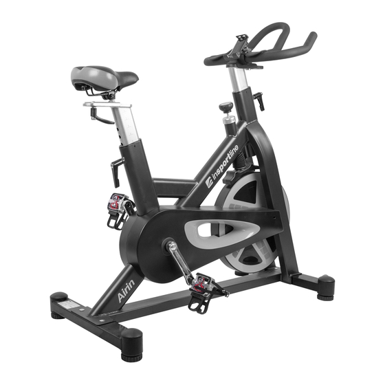
- Page 1 USER MANUAL – EN IN 9360 Spinning Bike inSPORTline Airin...
-
Page 2: Table Of Contents
CONTENTS IMPORTANT SAFETY INSTRUCTIONS ......................3 ASSEMBLY ................................4 HOW TO ADJUST THE RESISTANCE ......................10 HOW TO STOP THE BIKE IMMEDIATELY ....................10 PARTS LIST ................................. 10 EXPLODED VIEW .............................. 13 TERMS AND CONDITIONS OF WARRANTY, WARRANTY CLAIMS ............14... -
Page 3: Important Safety Instructions
IMPORTANT SAFETY INSTRUCTIONS WARNING! To reduce the risk of serious injury, read the following important precautions before using the Spin Bike. • Read all instructions and warnings in this manual before using the Spin bike. • Before using this spin bike, please consult your physician for a complete physical examination. If you feel any discomfort while exercising, please stop immediately and consult your doctor. -
Page 4: Assembly
ASSEMBLY Assembly requires two persons. Place all parts of the Spin bike in a cleared area and remove the packing materials. Do not dispose of the packing materials until assembly is completed. For your convenience, we have identified the hardware used in the assembly of this product. This chart is provided to help you identify those items that may be unfamiliar to you. - Page 5 STEP 1: Front / Rear Stabilizers Installation Hardware: (36) Carriage bolt, 4 PCS (35) Cap nut, 4 PCS (37) Washer, 4 PCS Tool: While another person lifts the front of Frame (1), attach the Front stabilizer (2) to the Frame with two M10x55mm Carriage bolts (36) from the above Stabilizer, and fix it with two 10x19x1.5mm Washers (37) &...
- Page 6 STEP 2: Handlebar Installation Hardware: (23) Knob M10x28mm, 1 (24) Lock nut M10, 1 PC (25) Washer (46) Washer 19.5x38x2mm, 1 PC 10x29x2mm, 1 PC Release the Spring knob (21), then insert the Upright post (4) into the Frame (1). There are 5 holes on the Upright post (4), please select the desired position and tighten the Spring knob (21).
- Page 7 STEP 3: Seat Post / Seat Installation Hardware: (22) L-knob M10, 1 PC (46) Washer 10x29x2mm, 1 PC Tool: Release the Spring knob (21), then insert the Seat post (5) into the Frame (1). There are 9 holes on the Seat post (5), please select the desired position and tighten the Spring knob (21).
- Page 8 STEP 4: R / L Pedals Installation Tool: Screw R/L pedals (20) onto crank (18). The pedals are marked with R and L at the screw. Tighten the left pedal counter-clockwise, the right pedal clockwise.
- Page 9 STEP 5: Bottle Holder Installation Tool: Release two M5x15mm Bolts (78) from the Frame (1), then put the Bottle holder (48) onto the Frame (1) and re- lock two Bolts (78).
-
Page 10: How To Adjust The Resistance
HOW TO ADJUST THE RESISTANCE Clockwise rotate the knob to increase the resistance, and counter-clockwise rotate the knob to decrease the resistance as below images. HOW TO STOP THE BIKE IMMEDIATELY When you want to stop the bike in training, please push down the knob as below image. PARTS LIST Description Unit... - Page 11 Belt wheel Φ260 Belt 1590 PK5 Main chain cover-R Main chain cover-L Inner chain cover-R Inner chain cover-L Side trim cover 3PCS Crank Plastic cap for Crank Pedal JD-304V Spring knob M16x26 L-knob M10x20 Knob M10x28 Lock nut M10 Washer 19.5x38x2T Magnet plastic cover Support bar 20x20x1.4T Magnet bracket...
- Page 12 Screw M5x10 Philips screw M3x10 Washer 20.5x25x1T Self-tapping screw M4.5x15 Self-tapping screw M4.2x10 Hex bolt M6x35 Idle wheel fixture Nylon nut M10x6T Steel sleeve Φ25.1x32x10T Steel bearing 6005-2RS C-ring Φ20 C-ring Φ25 Steel bearing 6004-2RS Wave washer 27x34x0.3T Plastic washer 10x20x2T Wire plug Φ17 Steel sleeve Φ10.2x15x6T Axis Φ20x155mm...
-
Page 13: Exploded View
EXPLODED VIEW... -
Page 14: Terms And Conditions Of Warranty, Warranty Claims
TERMS AND CONDITIONS OF WARRANTY, WARRANTY CLAIMS General Conditions of Warranty and Definition of Terms All Warranty Conditions stated hereunder determine Warranty Coverage and Warranty Claim Procedure. Conditions of Warranty and Warranty Claims are governed by Act No. 40/1964 Coll. Civil Code, Act No. 513/1991 Coll., Commercial Code, and Act No. - Page 15 require a compensation for all the costs arising from the repair. The cost shall be calculated according to the valid price list of services and transport costs. If the Seller finds out (by testing) that the product is not damaged, the Warranty Claim is not accepted. The Seller reserves the right to claim a compensation for costs arising from the false Warranty Claim.
Need help?
Do you have a question about the IN 9360 Airin and is the answer not in the manual?
Questions and answers