Table of Contents
Advertisement
Quick Links
Advertisement
Table of Contents

Related Manuals for APPA 607


Summary of Contents for APPA 607
- Page 1 APPA 607 User Manual...
-
Page 2: Safety Information
Safety sheet Warning Warning Safety sheet ........ -
Page 3: Unsafe Voltage
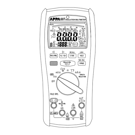
CAUTION ˙ Disconnect the test leads from the test points before chang- ing the position of the function rotary switch. ˙ Never connect a source of voltage with the function rotary switch in Ω, ,°C ,mA, INSULATION position. ˙ Do not expose Meter to extremes in temperature or high humidity. - Page 4 The Meter Description Front Panel Illustration 1. LCD display : 10000 counts . 2. Push-buttons for features. 3. Rotary switch for turn the Power On / Off and select the function. 4. Input Terminal for Insulation function. 5. Input Terminal for V,Ω, , Hz, °C functions.
-
Page 5: Making Basic Measurements
Making Basic Measurements Preparation and Caution Before Measurement : Observe the rules of Warnings and Cautions When connecting the test leads to the DUT (Device Under Test) connect the common (mA) test lead before connecting the live lead ; when removing the test leads removing the test live lead before removing the common test lead. -
Page 6: Testing Diode
Measuring Resistance / Continuity / Diode Measuring Resistance / Continuity / Diode Press the Blue button to select the measuring function. Testing Diode... -
Page 7: Testing Continuity
Testing Continuity The buzzer allows you to quick continuity tests without having to watch the display. The buzzer sounds when a short (< 30Ω) is defected. Measuring Capacitance... - Page 8 Measuring Temperature °C / °F Measuring AC / DC Current...
-
Page 9: Measuring Insulation Resistance
Measuring Insulation Resistance Select test voltage Press the Range button to select the test voltage (50V / 100V / 250V / 500V / 1000V) Lock test voltage Press the Hold button to lock the test voltage. Press the button again to cancel the lock mode. Make the reading stably Press the Blue button to make the reading stably, the “Smooth”... - Page 10 Measuring Insulation Resistance Insulation tests should only be performed on dead circuits. Check the fuse before testing. To measure insulation resis- tance, follow the steps below. 1. Insert test probes in the “⊕ “ and “ “ input terminals. 2. Turn the rotary switch to Insulation position. 3.
-
Page 11: Display Hold
Measuring Frequency for ACV, ACmV and ACmA The meter measures the frequency of a voltage or current signal by counting the number of times the signal crosses a threshold level each second. To measure frequency, follow the steps below. 1. Turn the rotary switch to V, mV or mA position. 2. - Page 12 Display MAX / MIN / AVG The “MIN/MAX/AVG“ mode records minimum and maximum input values. When the inputs go below the recorded minimum value or above the recorded maximum value, the meter beeps and records the new value. MIN/MAX/AVG mode can also calculate an average of maximum and minimum.
- Page 13 Relative mode for Ω / In the Relative mode, the meter records the present reading as reference and the later reading will subtract it. To use the Relative mode, follow the steps below. 1. Turn the rotary switch to Ω or position.
- Page 14 Auto Test and Manual Test The meter has both “AutoTest “ mode and Manual Test mode. ˙In the Auto Test mode, the meter compares the reading of AC and DC, and the bigger reading appears on the display. The meter beeps when the AC/DC mode has change. ˙In the Manual Test mode, you override “AutoTest “...
-
Page 15: Auto Range And Manual Range
Auto Range and Manual Range The meter has both Auto Range mode and Manual Range mode. ˙ In the Auto Range mode, the meter selects the range with the best resolution. ˙ In the Manual Range mode, you select the range yourself. When you turn the meter on, it defaults to Auto Range mode and the “Range”... -
Page 16: Store And Recall
Store and Recall You can store the reading on the display, and recall the reading on the display after. ˙To store the reading press the Store button. The data amount and “MEM” blink on the secondary display. ˙Each function has a separate memory space. Each memory space has the maximum 100 amounts. -
Page 17: Auto Power Off
Auto Power Off Wake-up the meter by switching rotor or pressing any button. Auto Backlight The backlight is automatically turned on at dark environment. BUZZER The meter beeps once for every valid key-press, and beeps twice for every invalid key-press. Power On Options Press button while turning the meter on from OFF position. -
Page 18: Battery And Fuse Replacement
Battery and Fuse Replacement Refer to the following figure to replace fuse and the batteries : Caution ˙Use only a fuse with the amperage, interrupt, voltage, and speed rating specified. ˙ Fuse rating : 440mA,1000V fast blow fuse. ˙ Replace the batteries as soon as the low batteries indicator "... -
Page 19: Testing The Fuse
Testing the fuse Test the fuse as described below. 1. Insert a test probe in the V, Ω, , Hz, °C input terminal. 2. Turn the rotary switch to Ω position, and press the Blue button to diode function. 3. Insert the probe in the mA input terminal. If the display reading is 0L, the fuse is bad and should be replaced. -
Page 20: Specifications
Specifications General Specifications Maximum voltage applied to any terminal : 1000 V ac rms or dc. Display : 10000 counts. Polarity Indication : Automatic, positive implied, negative indicated. Overrange Indication : OL Batteries Life : ALKALINE 80 hours. Insulation test : Tester can perform at least insulation tests with new alkaline batteries at room temperature. -
Page 21: Electrical Specifications
EMC : EN 61326-1 Shock vibration : Sinusoidal vibration per MIL-T- 28800E (5 ~ 55 Hz, 3g maximum). Drop Protection : 4 feet drop to hardwood on concrete floor. Indoor Use. Electrical Specifications Accuracy is ±(% reading + number of digits) at 23°C ± 5°C <... - Page 22 CMRR / NMRR : (Common Mode Rejection Ratio) (Normal Mode Rejection Ratio) : CMRR > 60dB at DC, 50Hz / 60Hz : CMRR > 100dB at DC, 50Hz / 60Hz NMRR > 50dB at DC, 50Hz / 60Hz AC Conversion Type : AC conversions are ac-coupled, true rms responding, calibrated to the sine wave input.
- Page 23 Frequency Counter Sensitivity Sensitivity (RMS Sine Wave) Input Range Function (AC) 10Hz to 10kHz 10kHz to 100kHz 100.00mV 15.00mV 15.00mV ACmV 150.0mV 150.0mV 1000.0mV 1.500V 1.500V 10.000V 100.00V 1000.0V 15.00mA 100.00mA ACmA 30mA 400.0mA Minimun Pulse Width : >10us Overload Protection : 1000V AC rms or DC Resistance Measurement Function Range...
- Page 24 Capacitance Measurement Function Range Measuring Time Accuracy 10.000nF 0.7sec ±(1.2%+80d) 100.00nF 0.7sec ±(1.2%+20d) 1000.0nF 0.7sec ±(1.2%+2d) 10.000uF 0.7sec ±(1.2%+2d) Capacitance 100.00uF 0.7sec ±(1.2%+2d) 1000.0uF 3.75sec ±(1.2%+2d) 10.000mF 7.5sec ±(1.2%+20d) 40.00mF 7.5sec ±(1.2%+80d) Overload Protection : 1000V AC rms or DC Temperature Measurement Function Range...
- Page 25 Insulation Resistance Measurement Test Voltage Range Accuracy 2.000MΩ ±(1.5%+5d) 20.00MΩ ±(1.5%+5d) 55.0MΩ ±(1.5%+5d) 2.000MΩ ±(1.5%+5d) 100V 20.00MΩ ±(1.5%+5d) 110.0MΩ ±(1.5%+5d) 2.000MΩ ±(1.5%+5d) 20.00MΩ ±(1.5%+5d) 250V 200.0MΩ ±(1.5%+5d) 275MΩ ±(1.5%+5d) 2.000MΩ ±(1.5%+5d) 20.00MΩ ±(1.5%+5d) 500V 200.0MΩ ±(1.5%+5d) 550MΩ ±(1.5%+5d) 2.000MΩ ±(1.5%+5d) 20.00MΩ...
-
Page 26: Limited Warranty
Limited Warranty This meter is warranted to the original purchaser against defects in material and workmanship for 2 years from the date of purchase. During this warranty period, Manufacturer will, at its option, replace or repair the defective unit, subject to verification of the defect or malfunction. - Page 27 APPA TECHNOLOGY CORP. 9F.119-1 Pao-Zong Rd., Shin-Tien, Taipai, 23145, Taiwan, R.O.C. Tel : 886-2-29178820 Fax : 886-2-29170848 E-MAIL : info @appatech.com http ://www.appatech.com...
Need help?
Do you have a question about the 607 and is the answer not in the manual?
Questions and answers