Advertisement
Quick Links
INTRODUCTION
1-1 Unpacking and Inspection
Upon removing your new Clamp Multimeter from its packing, you should have the following items:
1. Clamp Multimeter.
2. Test lead set (one black, one red).
3. Carrying case.
4. Instruction manual.
1-2 Meter Safety
Terms as Marked on Equipment
ATTENTION — Refer to manual
DOUBLEINSULATION — Protection Class II
DANGER — Risk of electric shock.
1
Advertisement

Related Manuals for APPA 39MR


Summary of Contents for APPA 39MR
- Page 1 INTRODUCTION 1-1 Unpacking and Inspection Upon removing your new Clamp Multimeter from its packing, you should have the following items: 1. Clamp Multimeter. 2. Test lead set (one black, one red). 3. Carrying case. 4. Instruction manual. 1-2 Meter Safety Terms as Marked on Equipment ATTENTION —...
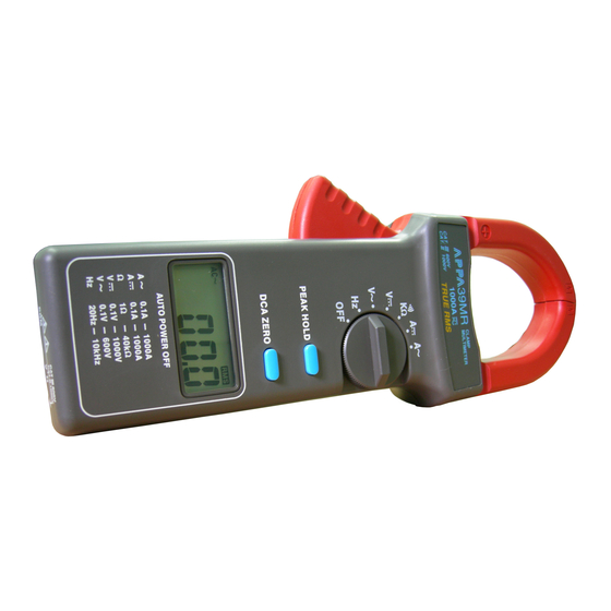
- Page 2 Symbols in this Manual This symbol indicates where cautionary or other information is found in the manual. Battery 1-3 Front Panel Refer to Figure 1 and the following numbered steps to familiarize yourself with the meter’s front panel controls and connectors. 1.
- Page 3 3. Function Switch — Rotary switch is used to select Hz, V , V , Ω, A , A function. 4. Trigger — Press the lever to open the transformer jaws. When the pressure on the lever is released, the jaws will close again.
- Page 4 Figure 1...
-
Page 5: Specifications
SPECIFICATIONS 2-1 General Specifications Display : 3 3/4 Digital Liquid Crystal Display ( LCD) with a maximum reading of 3999. Polarity : Automatic polarity indicated. Overrange Indication : “OL” or “-OL” indicated. Range : Autoranging. Measuring Rate : 2 times per second, nominal. Position Error : +/- 1% of Reading. - Page 6 Max/Conductor Size : 51mm diameter or 24 x 60mm busbar. Size : 100mm (W) x 265mm (L) x 42mm (H). Weight : 420 grams (including battery) Accessories : Test leads, battery (installed), manual and carrying case. 2-2 Environmental Conditions: Indoor use Maximum Altitude : 2000 Meter Installation Category...
- Page 7 2-3 Electrical Specifications Accuracy is ± (% reading + number of digits) at 23ºC ± 5ºC, less than 80% R.H. (1) Frequency : Hz Over Voltage Range Resolution Accuracy Protection 4KHz AC/DC 2000A ±(0.5% rdg + 3 dgt) for 1 min. 10KHz 10Hz Min.
- Page 8 (2) ACV : V Range Resolution Accuracy Overload Protection 400V 0.1V ±(1.2% rdg + 5 dgt) 850V rms 50Hz -500Hz 600V Additional error according to crest factor (CF) : CF from 2 to 3 : + 1.4% CF from 3 to 4 : + 3% Input impedance : 10MΩ...
- Page 9 (4) Resistance : Ω Max. Open Overload Range Resolution Accuracy Circuit Voltage Protection 4KΩ 1Ω ±(1.0% rdg + 2 dgt) 3.3V 600V r.m.s. 40KΩ 10Ω Instant Continuity Description : Built - in buzzer sound when resistance is less than 100Ω. (5) DCA : A Range Resolution...
- Page 10 Additional error according to remanence : 1% max. of current crest (6) ACA : A Frequency Overload Range Resolution Accuracy Response Protection 0 ~ 400A 0.1A ±(1.5% rdg + 5 dgt) 40 ~ 400 Hz AC 2000A 400 ~ 600A for 1 min.
-
Page 11: Operation
OPERATION This instrument has been designed and tested in accordance with IEC Publication 1010, Safety Requirements for Electronic Measuring Apparatus and has been supplied in a safe condition. This instruction manual contains some information and warnings which have to be followed by the user to ensure safe operation and to retain the instrument in safe condition. - Page 12 6. If the unit is not to be used for a long period of time, remove the battery. 7. Do not forget to turn off after use. THIS INSTRUMENT MUST NOT BE USED ON UNINSULATED CONDUCTORS AT A VOLTAGE GREATER THAN 600V ac/dc.
- Page 13 B. Frequency measurement by input terminal (AC voltage) 1. Set the rotary switch to "Hz" position. 2. Connect the black test lead to the “COM” terminal on the bottom of the meter and the red test lead to the "V Ω" terminal.
- Page 14 3-4 DC Voltage Measurement 1. Set the rotary switch at "V " position. 2. Connect the black test lead to the “COM” terminal on the bottom of the meter and the red test lead to the "V Ω” terminal. You can now place the test probes on the conductors to make the measurement. To avoid electrical shock, hazard or damage to the meter, do not attempt to measure voltage that might exceed 1000V dc between the common input terminal and earth ground.
- Page 15 3-6 DC Current Measurement Set the rotary switch at “A “ position at first. Low current : Press DCA ZERO switch before measuring. High current : 1. Enclose the conductor lead and close the clamp. 2. Remove the clamp and press the DCA ZERO switch . (remnant magnetization compensation) 3.
- Page 16 3-7 AC Current Measurement 1. Set the rotary switch at " A " position. 2. Open Spring-loaded clamp by pressing trigger on left side of meter. 3. Position clamp around wire or conductor and release clamp trigger, make sure that the clamp is entirely closed. The clamp must be positioned around only one conductor of a circuit.
-
Page 17: Maintenance
MAINTENANCE WARNING TO AVOID ELECTRICAL SHOCK REMOVE TEST LEADS BEFORE OPENING THE COVER. 4-1 General Maintenance 1. Repairs or servicing not covered in this manual should only be performed by qualified personnel. 2. Periodically wipe the case with a dry cloth and detergent do not use abrasives or solvents. 4-2 Battery Installation or Replacement The meter is powered by a single 9V battery. - Page 18 Battery Replacement Or Installation Figure 2...
Need help?
Do you have a question about the 39MR and is the answer not in the manual?
Questions and answers