Table of Contents
Advertisement
Quick Links
Advertisement
Table of Contents

Related Manuals for APPA 67


Summary of Contents for APPA 67
- Page 1 DIGITAL MULTIMETER INSTRUCTION MANUAL APPA 67...
- Page 2 INTRODUCTION 1-1 Unpacking and Inspection Upon removing your new Digital Multimeter from its packing, you should have the following items: 1. Digital Multimeter. 2. Test lead set (one black, one red). 3. Operators Manual. 4. Holster. 1-2 Meter Safety Terms as Marked on Equipment ...
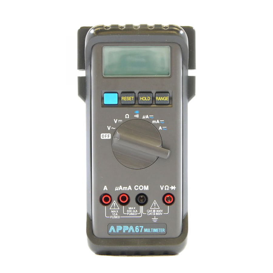
- Page 3 Symbols in this Manual This symbol indicates where cautionary or other information is found in the manual. Fuse Battery 1-3 Front Panel Refer to Figure 1 and the following numbered steps to familiarize yourself with the meter's front panel controls and connectors.
- Page 4 5. µA mA Input Terminal — Positive input connector for current and measurements. (up to 300mA). 6. A Input Terminal — Positive input connector for current measurements, up to 10A. 7. Function Switch (Blue) — Press the switch to measure AC voltage or DC voltage in the Voltage mode or to measure AC current or DC current in the current mode, or to measure continuity or diode check in ;/ ...
- Page 5 Figure 1...
-
Page 6: Specifications
SPECIFICATIONS 2-1 General Specifications Display : The Liquid Crystal Display (LCD) has a maximum reading of 3200, and 65 segments bar graph. Polarity Indication : Automatic, positive implied, negative indicated. Overrange Indication : "OL" or "-OL". Low Battery Indication : " " is displayed when the battery voltage drops below operating voltage. Sampling : 2 times/sec for digit. - Page 7 2-2 Environmental Conditions For indoor use. Maximum Altitude : 2000m. Pollution Degree : 2 Operating Ambient : 0°C to 50°C, 0 to 80% R.H. Storage Temperature : -20°C to 60°C, 0 to 80% R.H. with battery removed from meter. Installation Category : IEC 61010, 600V CAT II. Application field The circuits not connected to mains.
- Page 8 2-3 Electrical Specifications Accuracy is ± (% reading + number of digits) at 23C ± 5C less than 80% R.H. (1) DC Volts Range Resolution Accuracy Over voltage protection 300mV 100µV 10mV ±(0.7%reading + 2digits) 600Vd.c. or 600Va.c.rms 300V 100mV 600V Input Impedance : 10MΩ.
- Page 9 (2) AC Volts Range Resolution Accuracy Over voltage protection ±(1.7%reading + 5digits) 10mV 600Vd.c. or 600Va.c.rms ±(1.7%reading + 5digits) 300V 100mV 40Hz to 400Hz 600V * Frequency Response : 40Hz ~ 300Hz for 3V Range. AC Conversion Type : Average Sensing rms indication. Input Impedance : 10MΩ...
- Page 10 (3) DC Current Range Resolution Accuracy Voltage Burden 300µA 0.1µA 200mV max 1µA 2V max ±(1.2%reading + 2digitst) 30mA 10µA 200mV max 300mA 0.1mA 2V max 10mA 2V max ±(2.5%reading + 5digits) * 20A Range : 30 seconds maximum above 10A input. Overload Protection : 1A/240V fast for µA/mA input.
- Page 11 (4) AC Current Range Resolution Accuracy Voltage Burden 300µA 0.1µA 200mV max 1µA 2V max ±(1.7%reading + 4digits) 30mA 10µA 200mV max 300mA 0.1mA ±(2.0%reading + 4digits) 2V max 10mA ±(2.9%reading + 7digits) 2V max * Frequency Response : 40Hz ~ 500Hz. * 20A Range : 30 seconds maximum above 10A input.
- Page 12 (5) Resistance Range Resolution Accuracy Voltage Burden 300Ω 0.1Ω ±(1.2%reading + 4digits) 3KΩ 1Ω 30KΩ 10Ω ±(0.9%reading + 2digits) 600Vd.c. or 600Va.c. rms 300KΩ 100Ω 3MΩ 1KΩ ±(1.2%reading + 3digits) 30MΩ 10KΩ ±(2.5%reading + 5digits) * Open Circuit Voltage : 1.3V approx.
- Page 13 (6) Diode Check and Continuity Max. Open Range Resolution Accuracy Max. Test Current Circuit Voltage ±(1.5%reading + 5digits) 1.5mA 3.3V *For 0.4V ~ 0.8V. Overload Protection: 600V DC/AC rms max. Continuity: Built-in sounder will operate when resistance is less than 30Ω. (7) Auto Power Off The meter will automatically shut itself off approximately 10 minutes after power on unless the value being measured changes within this time.
-
Page 14: Operation
OPERATION This instrument has been designed and tested in accordance with IEC Publication 1010, Safety Requirements for Electronic Measuring Apparatus and has been supplied in a safe condition. This instruction manual contains some information and warnings which must be followed by the user to ensure safe operation and to retain the instrument in safe condition. - Page 15 3-2 Voltage Measurements 1. Connect the red test lead to the "VΩ" input terminal and the black test lead to the "COM" terminal. 2. Set the rotary function switch to the ACV or DCV position. 3. Connect the test leads to the device to be measured. 4.
- Page 16 WARNING TO AVOID ELECTRIC SHOCK HAZARD, OR DAMAGE TO THE METER, DO NOT ATTEMPT TO MEASURE VOLTAGES THAT MIGHT EXCEED 600 VOLTS d.c. OR 600 VOLTS a.c.. DO NOT APPLY MORE THAN 600V d.c. OR 600V a.c. RMS BETWEEN THE COMMON INPUT TERMINAL AND EARTH GROUND. 3-3 Resistance Measurement 1.
- Page 17 3-4 Continuity Check by Sounder 1. Connect the red test lead to the "VΩ" terminal and the black test lead to the "COM" terminal. 2. Set the rotary function switch to " " position. 3. Connect the test leads to the circuit to be measured. The sounder will operate if the resistance of the circuit measured is lower than 30Ω.
- Page 18 3-6 Current Measurement 1. Connect the red test lead to "µA/mA" terminal and the black test lead to "COM" terminal or use the "A" and "COM" terminal in the "A" range. 2. Set the function selector rotary switch to "µA" or "mA" or "A". 3.
-
Page 19: Maintenance
MAINTENANCE WARNING : TO AVOID ELECTRICAL SHOCK REMOVE TEST LEAD BEFORE OPENING THE COVER. 4-1 General Maintenance To keep the instrument clean, wipe the case with a dry cloth and detergent, do not use abrasives or solvents. Any adjustment, maintenance and repair of the opened instrument under voltage shall be avoided as far as possible and, if inevitable, shall be carried out by a skilled person who is aware of the hazard involved. -
Page 20: Battery Installation Or Replacement
4-2 BATTERY INSTALLATION OR REPLACEMENT The meter is powered by two 1.5V batteries. Refer to Figure 2A and use the following procedure to replace the batteries: 1. Disconnect the test leads and turn the meter off. Remove the test leads from the front terminals. 2. -
Page 21: Fuse Replacement
4-3 FUSE REPLACEMENT Refer to Figure 2B and use the following procedure to examine or replace the meter's fuse: 1. Perform steps 1 through 4 of the battery replacement procedure. 2. Lift the circuit board from case top. Do not remove the screws from the circuit board. 3. -
Page 22: Battery Replacement
BATTERY REPLACEMENT Case Bottom 1.5V x 2 Batteries Fuse 13A/240V Case Top Fuse 1A/240V Battery Box Battery Connector Figure 2A Figure 2B... - Page 23 HOW TO USE THE PROBE HOLDER Wrap the leads around the holster to store the test probes.
- Page 24 HOW TO USE THE PROBE HOLDER Slide out one probe holder for one handed meter operation.
- Page 25 HOW TO USE THE TILT STAND AND HOLSTER Swing the stand out for Swing the upper holder out easier meter reading. and hook it over a door. Hang on a nail at the workbench.
- Page 26 APPA TECHNOLOGY CORP. 9F.119-1 Pao-Zong Rd., Shin-Tien, Taipai, 23115, Taiwan, R.O.C. P.O.Box. 12-24 Shin-Tien, Taiwan. Tel : 886-2-29178820 Fax : 886-2-29170848 e-mail:info @appatech.com http://www.appatech.com Printed In Taiwan Copright 2005, APPA Tech., Corp. All rights reserved.
Need help?
Do you have a question about the 67 and is the answer not in the manual?
Questions and answers