Advertisement
Quick Links
Advertisement

Related Manuals for APPA 36II


Summary of Contents for APPA 36II
- Page 1 AC/DC CLAMP MULTIMETER INSTRUCTION MANUAL APPA 36Ⅱ/36RⅡ...
- Page 2 INTRODUCTION 1-1 Unpacking and Inspection Upon removing your new Digital Clamp Multimeter from its packing, you should have the following items: 1. Digital Clamp Multimeter. 2. Test lead set (one black, one red). 3. Carrying case. 4. Instruction manual. 5. Battery. 1-2 Meter Safety Terms as Marked on Equipment.
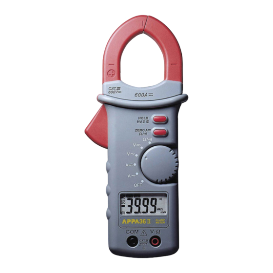
- Page 3 Symbols in this Manual. This symbol indicates where cautionary or other information is found in the manual. Battery 1-3 Front Panel Refer to Figure 1 and the following numbered steps to familiarize yourself with the meter’s front panel controls and connectors. 1.
- Page 4 4. HOLD/MAX( ) — This button has two modes one is data hold (A) and the other is maximum hold (B). (A) Turning the rotary switch to power on, the button will work in data hold mode. Press to toggle data hold ON/OFF.
- Page 5 Figure 1...
-
Page 6: Specifications
SPECIFICATIONS 2-1 General Specifications Display : 3 3/4 Digital Liquid Crystal Display (LCD) with a maximum reading of 3999. Polarity : Automatic polarity indicated. Over range Indication : “OL” indicated. Low Battery Indication : “ “ is displayed when the battery voltage drops below the operating voltage. Measuring Rate : 2 times/second, normal. - Page 7 Max/Conductor Size : 35 mm diameter. Temperature Coefficient : 0.2 x ( spec.Acc’y ) / ℃ < 18℃, > 28℃. Size : 82 mm (W) x 208 mm (L) x 41 mm (H) . Weight : 360 grams (including battery) Accessories : Test leads, battery, manual and carrying case.
- Page 8 2-2 Electrical Specifications Accuracy is ± (% reading + number of digits) at 23℃ ± 5℃ at less than 80% R.H. (1) AC Voltage : Auto-ranging Over voltage Range Resolution Accuracy protection μ Unspecified 400.0mV 4.000V ±(1.5% reading + 5digits ) 40Hz ~ 300Hz 600V rms 40.00V 10mV...
- Page 9 AC Conversion Type : 36Ⅱ: AC conversion are average sensing rms indication calibrated to the rms value of a sine wave input. 36RⅡ: AC conversions are ac-coupled, true rms responding, calibrated to the rms value of a sine wave input . Accuracies are given for sine wave at full scale and non-sine wave below half scale.
- Page 10 (2) DC Voltage : Auto-ranging Over voltage Range Resolution Accuracy protection 400.0mV μ 4.000V 600V rms 40.00V 10mV ±(0.7% reading + 2 digits) 400.0V 100mV 600V Input Impedance : ≧ 9MΩ.
- Page 11 (3) Resistance Auto-ranging Overload Range Resolution Accuracy Protection 400.0Ω 100mΩ ±(1.2% reading + 6 digits) 4.000KΩ 1Ω ±(0.9% reading +3 digits) 40.00KΩ 10Ω 600V rms 400.0KΩ 100Ω ±(1.2% reading + 3 digits) 4.000MΩ 1KΩ 40.00MΩ 10KΩ ±(2.5% reading + 5 digits) *1 *3...
- Page 12 * 1: The reading maybe rolling ≦ 6 digits when the reading is close to full scale. * 2: The reading maybe rolling ≦ 3 digits when the reading is close to full scale. * 3: The response time is approximate 20 seconds. * : Put a low resistor in the input terminal before turn the rotary function switch to resistor and continuity function maybe cause a buzzer sound.
- Page 13 (5) DCA : Auto-ranging Range Resolution Accuracy Over voltage protection 0 ~ 40.0A 0.1A ±(1.5% reading + 10 digits) 40.0A ~ 400.0A 0.1A ±(1.5% reading + 7 digits) * 600A rms 400A ~ 600A ±(1.9% reading + 10 digits) 1. * For 200.0A ~ 400.0A add 1% to accuracy. 2.
- Page 14 (6) ACA : Auto-ranging Frequency Overload Range Resolution Accuracy Response Protection 0 ~ 40.0A 0.1A ±(1.9% reading + 7 digits) 40.0A ~ 400.0A 0.1A 50Hz ~ 60Hz ±(1.9% reading + 5 digits) ** 400A ~ 600A ±(1.9% reading + 10 digits) 600A r.m.s.
- Page 15 3. Temperature Coefficient : 0.2 x (Spec.Acc'y) /℃ < 21 ℃ or > 26℃. 4. Operating Temperature : 0℃ to 30℃ (≦ 80%RH) , 30℃ to 40℃ (≦ 75%RH) AC Conversion Type : 36Ⅱ: AC conversion are average sensing rms indication calibrated to the rms value of a sine wave input.
- Page 16 (7) Maximum Hold 7-1 In maximum hold function the accuracy is changed as following. Original Accuracy + 10 digitals/ change steps of range . For example : At First , the maximum hold reading on display is 100.0mV on 400.0mV range. If a voltage vibration changes the maximum hold reading to 120.0V.
-
Page 17: Operation
OPERATION This instrument has been designed and tested in accordance with IEC Publication 1010, Safety Requirements for Electronic Measuring Apparatus and has been supplied in a safe condition. This instruction manual contains some Information and warnings which have to be followed by the user to ensure safe operation and to retain the instru- ment in safe condition. - Page 18 5. Do not replace battery with power on condition. 6. If the unit is not to be used for a long period of time , remove the battery. 7. Do not forget to turn off after use. Maximum rated voltage to earth for voltage measurement terminals is 600V CAT.III THIS INSTRUMENT MUST NOT BE USED ON UNINSULATED CONDUCTORS AT A VOLTAGE GREATER THAN 600V ac/dc.
- Page 19 3-2 AC/DC Current Measurement 1. Turning the rotary switch at “A ” or “A “ position. 2. Open clamp by pressing trigger on left side of meter. 3. Position clamp around wire or conductor and release clamp trigger smoothly , do not release quickly, make sure that the clamp is entirely closed.
- Page 20 Figure 2...
- Page 21 3-3 AC/DC Voltage Measurement 1. Turning the rotary switch at " V " or “V “ position. 2. Connect the black test lead to the "COM" terminal on the bottom of the meter and the red test lead to the "...
-
Page 22: Maintenance
MAINTENANCE WARNING : TO AVOID ELECTRICAL SHOCK OR DAMAGE REMOVE TEST LEADS BEFORE OPENING THE COVER. 4-1 General Maintenance 1. Repairs or servicing not covered in this manual should only be performed by qualified personal. 2. Periodically wipe the case with a dry cloth and mild detergent do not use abrasives or solvents. 4-2 Battery Installation or Replacement The meter is powered by single 9V standard battery. - Page 23 Screw Battery Cover Battery Connector 9V Battery Figure 3...
- Page 24 APPA TECHNOLOGY CORP. 9F.119-1 Pao-Zong Rd., Shin-Tien, Taipai, 23115, Taiwan, R.O.C. P.O.Box. 12-24 Shin-Tien, Taiwan. Tel : 886-2-29178820 Fax : 886-2-29170848 E-MAIL:info @appatech.com http://www.appatech.com Printed In Taiwan Copright 2001, APPA Tech., Corp. All rights reserved.
Need help?
Do you have a question about the 36II and is the answer not in the manual?
Questions and answers