Table of Contents
Advertisement
Quick Links
Advertisement
Table of Contents

Subscribe to Our Youtube Channel
Related Manuals for APPA 33II


Summary of Contents for APPA 33II
- Page 1 CLAMP MULTIMETER INSTRUCTION MANUAL APPA 33Ⅱ/33RⅡ...
- Page 2 INTRODUCTION 1-1 Unpacking and Inspection Upon removing your new Digital Clamp Meter from its packing, you should have the following items: 1. Digital Clamp meter. 2. Carrying case. 3. Instruction manual. 4. Test lead set (one black, one red). 1-2 Meter Safety Terms as Marked on Equipment .
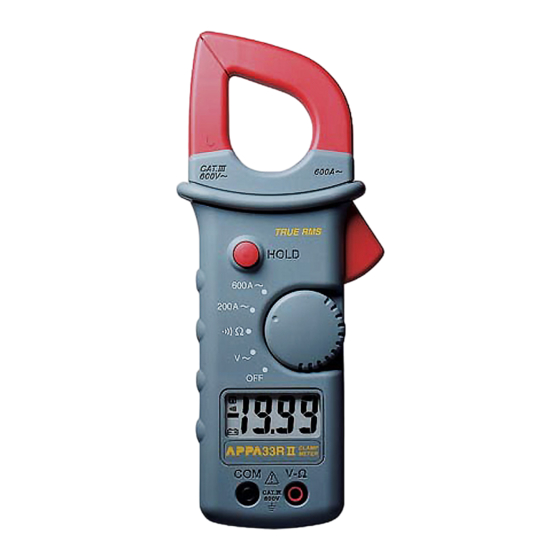
- Page 3 Symbols in this Manual This symbol indicates where cautionary or other information is found in the manual. Battery. 1-3 Front Panel Refer to Figure 1 and the following numbered steps to familiarize yourself with the meter’s front panel controls and connectors.
- Page 4 5. Trigger — Press the lever to open the transformer jaws. When the pressure on the lever is released, the jaws will close again. 6. Transformer Jaws — Designed to pick up the AC current flowing through the conductor. 7. Hand Guard — Designed to protect user for safety. 8.
- Page 5 Figure 1...
-
Page 6: Specifications
SPECIFICATIONS 2-1 General Specifications Display : 3 1/2 Digital Liquid Crystal Display (LCD) with a maximum reading of 1999. Overrange Indication : “1” indicated, show the real value for “V” function and 600A range of “A” function. Measuring Rate : 4 times per second, nominal. Low Battery Indication : is displayed when the battery voltage drops below the operating voltage. - Page 7 Temperature Coefficient : 0.2 x (Spec.Acc'y) / °C , < 18 °C or > 28°C. Power Requirement : Single 9V battery (NEDA 1604,IEC 6F22) Battery Life : Alkaline 400 hours. Shock Proof : 4 feet drops. Maximum Jaw Opening : 42mm Maximum Conductor Size : 40mm diameter.
-
Page 8: Electrical Specifications
2-3 Electrical Specifications Accuracy is ±(%reading + number of digits) at 23 °C ± 5 °C , less than 75% R.H. (1) AC Voltage : Auto-ranging Overload Range Resolution Accuracy protection ±(1.2%rdg + 3dgt) 600V 600V r.m.s. 40Hz ~ 500Hz * AC Conversion Type : Average Sensing rms indication. - Page 9 (2) AC Current : Auto-ranging Overload Range Resolution Accuracy protection 200A 0.1A ±(1.9%rdg + 5dgt) 50/60Hz 800A ±(1.5%rdg + 5dgt) 50/60Hz (for 0 ~ 400A) 600A ±(2.5%rdg + 5dgt) 50/60Hz (for 400 ~ 600A) * AC Conversion Type : Average Sensing rms indication. (33Ⅱ) AC Conversions are ac-coupled, true rms responding , calibrated to the rms value since wave input , the basic accuracy is for sine wave at full scale, for non-sine wave accuracy reference to ** (33RⅡ)
-
Page 10: Overvoltage Protection
(3) Resistance : Auto - ranging Max. Open Over voltage Range Resolution Accuracy Circuit Voltage protection ±(1.5%rdg + 2dgt) 600V r.m.s. 2000Ω 1Ω (4) Instant Continuity Description : Built - in buzzer sound when resistance is less than approximately 50Ω . (5) Data Hold : Hold display reading for all functions and ranges. -
Page 11: Operation
OPERATION This instrument has been designed and tested in accordance with IEC Publication 1010, Safety Require- ments for Electronic Measuring Apparatus and has been supplied in a safe condition. This instruction manual contains some information and warnings which have to be followed by the user to ensure safe operation and to retain the instrument in safe condition. - Page 12 7. If the meter is used near equipment that generates electromagnetic noise, the display may be unstable or indicate large errors. Maximum rated voltage to earth for voltage measurements terminals is 600V CAT. Ⅲ. 9. When using the instrument as a Voltmeter or ohmmeter never clamp the jaws around or onto a conductor. THIS INSTRUMENT MUST NOT BE USED ON UNINSULATED CONDUCTORS AT A VOLTAGE GREATER THAN 600V ac/dc.
- Page 13 3-3 AC Voltage Measurement 1. Set the function switch at " V ~ " position. 2. Connect the black test lead to the "COM" terminal and the red test lead to the " V-Ω" terminal. You can now place the test probes on the conductors to make the measurement. 3-4 Resistance Measurement 1.
-
Page 14: Maintenance
MAINTENANCE WARNING : TO AVOID ELECTRICAL SHOCK REMOVE TEST LEAD BEFORE OPENING THE COVER. 4-1 General Maintenance 1. Repairs or servicing not converted in this manual should only be performed by qualified personal. 2. Periodically wipe the case with a dry cloth and detergent do not use abrasives or solvents 4-2 Battery Replacement WARNING : Before opening the battery cover, remove the test leads (or jaw) from the circuit and shut off the unit. - Page 15 Screw Battery Cover 9V Battery Top Case Bottom Case Figure 2...
- Page 16 APPA TECHNOLOGY CORP. 9F.119-1 Pao-Zong Rd., Shin-Tien, Taipai, 23115, Taiwan, R.O.C. P.O.Box. 12-24 Shin-Tien, Taiwan. Tel : 886-2-29178820 Fax : 886-2-29170848 E-MAIL:info @appatech.com http://www.appatech.com Printed In Taiwan 71-10660-1 Copright 2001, APPA Tech., Corp. All rights reserved.
Need help?
Do you have a question about the 33II and is the answer not in the manual?
Questions and answers