Advertisement
Quick Links
Advertisement

Related Manuals for APPA 30R


Summary of Contents for APPA 30R
- Page 1 AC/DC CLAMP MULTIMETER INSTRUCTION MANUAL APPA 30R...
- Page 2 Warning Safety sheet ........
- Page 3 Symbols as marked on the meter and Instruction manual Risk of electric shock See instruction manual DC measurement Equipment protected by double or reinforced insulation < Battery Earth AC measurement Conforms to EU directives Application around and removal from hazardous live conductors is permitted Do not discard this product or throw away...
- Page 4 INTRODUCTION 1-1 Unpacking and Inspection Upon removing your new Digital Clamp Multimeter from its packing, you should have the following items: 1. Digital Clamp Multimeter. 2. Test lead set (one black, one red). 3. Carrying case. 4. Instruction manual. 5. Battery.
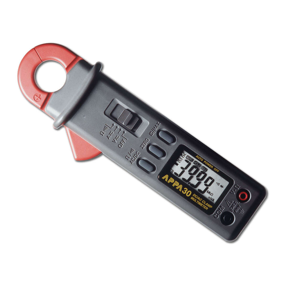
- Page 5 1-2 Front Panel Refer to Figure 1 and to the following numbered steps to familiarize yourself with the meter’s front panel controls and connectors. 1. Digital Display — The digital display has a 3 3/4 digit LCD readout (maximum reading 3999) plus decimal point , AC , DC , AUTO, HOLD, MAX , ;...
- Page 6 6. ZERO Switch —This switch is used to ZERO the reading on display. 7. Ω / ; AC/DC Selection Switch — Push the "Ω / ;, AC/DC" switch alternately to measure AC voltage or DC voltage in the " V H " function or to measure AC current or DC current in the " A H " function or to measure resistor or continuity in "...
- Page 7 Figure 1...
-
Page 8: Specifications
SPECIFICATIONS 2-1 General Specifications Display : 3 3/4 Digital Liquid Crystal Display (LCD) with a maximum reading of 3999. Polarity Indication : Automatic polarity indicated. Over range Indication : “OL” indicated. Low Battery Indication : ““ is displayed when the battery voltage drops below operating voltage. Measuring Rate : 2 times/second normal. - Page 9 Max/Conductor Size : 22 mm diameter. Temperature Coefficient : 0.15 x ( spec.Acc’y ) / °C < 18°C or > 28°C . Size : 66 mm (W) x 192 mm (L) x 27 mm (H) . Weight : 205 grams (including battery) Accessories : Test leads, battery, manual and carrying case.
- Page 10 2-3 Electrical Specifications Accuracy is ± (% reading + number of digits) at 23°C ± 5°C at less than 80% R.H. (1) AC Voltage : Auto-ranging Over voltage Range Resolution Accuracy protection μ 400.0mV ±(2.0% rdg + 5dgt ) 50Hz ~ 60Hz * 4.000V ±(1.5% rdg + 5dgt ) 40Hz ~ 300Hz 600V rms...
- Page 11 LCD display 0 count when the reading ≦1mV AC Conversion Type : AC conversions are ac-coupled, true rms responding, calibrated to the rms value of a sine wave input . Accuracies are given for sine wave at full scale. For distorted signals, add the following Crest Factor corrections: For Crest Factor of 1.4 to 2.0, add 1.0% to accuracy.
- Page 12 (2) DC Voltage : Auto-ranging Over voltage Range Resolution Accuracy protection μ 400.0mV ±(0.5% rdg + 5 dgt) 4.000V 600V rms 40.00V 10mV ±(0.5% rdg + 2 dgt) 400.0V 100mV 600V Input Impedance : ≧ 10MΩ.
- Page 13 (3) Resistance Auto-ranging Overload Range Resolution Accuracy Protection 400.0Ω 100mΩ ±(1.2% rdg + 6 dgt) 4.000KΩ 1Ω ±(0.9% rdg +3 dgt) 40.00KΩ 10Ω 600V rms 400.0KΩ 100Ω ±(1.2% rdg + 3 dgt) 4.000MΩ 1KΩ 40.00MΩ 10KΩ ±(2.5% rdg + 5dgt) *1 *3...
- Page 14 * 1: The reading maybe rolling ≦ 6 digits when the reading is close to full scale. * 2: The reading maybe rolling ≦ 3 digits when the reading is close to full scale. * 3: The response time is approximate 20 seconds. * : Put a low resistor in the input terminal before slide the sliding function switch to resistor and continuity function maybe cause a buzzer sound.
- Page 15 (5) DCA : Auto-ranging Over voltage Range Resolution Accuracy protection 0 ~ 40.00A 10mA ±(1.0% rdg + 2 dgt) 40.0A ~ 200.0A 100mA 400A rms 200.0A ~ 300.0A 100mA ±(2.0% rdg + 2 dgt) For DCA & ACA : 1. Temperature Coefficient : 0.2 x (Spec.Acc'y) / °C < 20 °C or > 26°C . 2.
- Page 16 (6) ACA : Auto-ranging Frequency Overload Range Resolution Accuracy Response Protection 0 ~ 4.00A 10mA ±(1.0% rdg + 5 dgt) 4.00A ~ 40.00A 10mA 50Hz ~ 60Hz ±(1.0% rdg + 3 dgt) 40.0A ~ 200.0A 100mA 200.0A ~ 300.0A 100mA ±(3.0% rdg + 3 dgt) 400A r.m.s.
- Page 17 LCD display 0 count when the reading ≦0.1A AC Conversion Type : AC conversions are ac-coupled, true rms responding, calibrated to the rms value of a sine wave input . Accuracies are given for sine wave at full scale. For distorted signals, add the following Crest Factor corrections : For Crest Factor of 1.4 to 2.0, add 1.0% to accuracy.
-
Page 18: Operation
OPERATION This instrument has been designed and tested in accordance with IEC 61010, Safety Requirements for Electronic Measuring Apparatus and has been supplied in a safe condition. This instruction manual contains some Information and warnings which have to be followed by the user to ensure safe operation and to retain the instrument in safe condition. - Page 19 THIS INSTRUMENT MUST NOT BE USED ON UNINSULATED CONDUCTORS AT A VOLTAGE GREATER THAN 600V ac/dc. 3-2 AC/DC Current Measurement 1. Set the slide switch at " A A " position. 2. Open Spring-loaded clamp by pressing trigger on left side of meter. 3.
- Page 20 Figure 2...
- Page 21 Figure 3...
- Page 22 3-3 AC/DC Voltage Measurement 1. Set the slide switch at " V A " position. 2. Connect the black test lead to the "COM" terminal on the bottom of the meter and the red test lead to the " V-Ω" terminal . You can now place the test probes on the conductors to make the measurement. 3.
-
Page 23: Maintenance
MAINTENANCE WARNING : TO AVOID ELECTRICAL SHOCKS REMOVE TEST LEADS FROM INSTRUMENT BEFORE OPENING THE COVER. 4-1 General Maintenance 1. Repairs or servicing not covered in this manual should only be performed by qualified personal. 2. Periodically wipe the case with a dry cloth and detergent do not use abrasives or solvents. 4-2 Battery Installation or Replacement The meter is powered by two 1.5V alkaline battery. - Page 24 Screw Battery Cover Battery Figure 4...
- Page 25 APPA TECHNOLOGY CORP. 9F.119-1 Pao-Zong Rd., Shin-Tien, Taipai, 23115, Taiwan, R.O.C. P.O.Box. 12-24 Shin-Tien, Taiwan. Tel : 886-2-9178820 Fax : 886-2-9170848 E-MAIL:info @appatech.com http://www.appatech.com Printed In Taiwan Copright 2013, APPA Tech., Corp. All rights reserved.
Need help?
Do you have a question about the 30R and is the answer not in the manual?
Questions and answers