Table of Contents
Advertisement
Advertisement
Table of Contents

Subscribe to Our Youtube Channel
Related Manuals for APPA 107N


Summary of Contents for APPA 107N
- Page 1 APPA 107N/109N DIGITAL MULTIMETER INSTRUCTION MANUAL...
-
Page 2: Table Of Contents
TABLE OF CONTENTS 1. SAFETY 2. PRODUCT DESCRIPTION 3. PANELS OVERVIEW 3.1 REAR PANEL 4. BUTTONS FUNCTION 4.1 LIGHT (Yellow Button) 4..2 BAR 4.3 PEAK HOLD 4.4 AUTO HOLD 4.5 BLUE 4.6 M/M/A 4.7 REL △ 4.8 RANGE 4.9 dB/dBm 4.10 STORE 4.11 RECALL 4.12 RED (Data Log) -
Page 3: Safety
1. SAFETY Review the following safety precautions to avoid injury and prevent damage to this product or any products connected to it. To avoid potential hazards, use the prod- uct only as specified. CAUTION. These statements identify conditions or practices that could result in damage to the equipment or other property. -
Page 4: Product Description
The meters provide many functions and features, Depending on your meter type, each type of meter has own features described in this manual. The following list provides a comparison of the features between meters. FUNCTION 107N 109N • • DC Voltage •... - Page 5 FEATURES 107N 109N • • Auto Power Off (30 minutes) • • Analog Bargraph Display , 42 Segments Graph • • Center Zero Analog Bargraph • • Auto Calibration • • Auto HOLD • • Autorange With Rang HOLD •...
-
Page 6: Panels Overview
3. FRONT PANEL OVERVIEW Figure 1 1. Input connectors. 2. Measurement function dial. Black labels are the initial settings, blue labels are selected by the blue button. 3. Function buttons. 4. Data log features. 5. LCD display with dual numeric readout. -
Page 7: Rear Panel
3-1 DISPLAY INDICATORS Figure 2 1. Auto range indicator. 2. True RMS mode indicator. 3. AC, DC and AC + DC mode indicators. 4. Low voltage resistance indicator. 5. Auto hold indicator. 6. Peak hold indicator. 7. Maximum, Minimum and Average indicators. 8. -
Page 8: Buttons Function
Indicator Unit Indicator Unit µ micro Volt milli Ampere kilo Farad mega Hertz △ delta Second percent Fahrenheit ℃ Decibel (1V ref.) Celsius Ω Decibel(1mW on 600Ω) gega nano 4. BUTTONS FUNCTION Prediction : Buzzer beeps once for every key-press. Buzzer beeps twice for every invalid key-press. -
Page 9: Peak Hold
4.3 PEAK HOLD * This button longlegs the peak hold on and off. * On the peak hold mode, push the M/M/A button to toggle peak hold max and min values. * The beeper sounds when new minimum or maximum values are detected. 4.4 AUTO HOLD * Auto hold is activated when a stable reading is first achieved. -
Page 10: Db/Dbm
4.9 dB/dBm * Pressing RANGE key for ≧ 2 sec enables "dB/dBm" function in AC Volt mode; One press in this mode toggles dB and dBm. * The reading of dB or dBm appears on sub-display, reference resistance for dBm is 600Ω and reference voltage for dB is 1V. * Again 2 sec press on this key in this mode escaps. -
Page 11: Data Log-In
* While data log-in performing, the “—” sub-display is blinking for storing indication. * When stores data at 40Kth (6Kth for 107N), data log-in stops, the bar is full (for 109 only) , sub-display keeps blinking “—” and showing FULL. -
Page 12: Dtgit
4.13 DIGIT * Pressing on BAR key for ≧ 2 sec enables “DIGIT” function, again 2 sec pressing excapes. * Press under this mode toggles 20000 / 4000 count modes. * Rotate to power OFF then on to reset to 20000 count mode (default). * This key is not available on following items. -
Page 13: Operation
5 OPERATION 5.1 VOLTAGE MEASUREMENTS (AC, DC, AC + DC) (Set to autoranging mode for unknown voltage measurements). * Set dial. * Choose AC, DC or AC + DC * Connect leads * The AC and AC + DC measurements provide a true RMS measurement. * In AC mode, the frequency of the measured signal ≧20% of full scale is displayed on sub-display. -
Page 14: Milli Voltage Measurements (Ac,Dc,Ac + Dc)
5.2 Milli VOLTAGE MEASUREMENTS (AC, DC, AC + DC) * Set dial. * Choose AC, DC or AC + DC *Connect leads * The AC and AC + DC measurements provide a true RMS measurement. * In AC mode, the frequency of the measured signal ≧20% of full scale is displayed on sub-display. -
Page 15: Ohm And Low Voltage Ohm Measurements
5.3 OHM AND LOW VOLTAGE OHM MEASUREMENTS * Set dial. * Choose Ω or LV Ω *Connect leads CAUTION : Remove all power from the circuit before connecting the test leads. * LV setting reduces the maximum test voltage level to about 0.5V to avoid turning on semiconductor devices. -
Page 16: Diode Test
5.4 DIODE TEST * Set dial. * Choose diode test. *Connect leads Forward bias Good = 0.4 to 0.9V Bad = o or = > 2.0V Reverse bias Good = OL Bad = <2.0V CAUTION : Remove all power from the circuit before connecting the test leads. -
Page 17: Continuity Check
5.5 CONTINUITY CHECK * Set dial. * Choose diode test. *Connect leads CAUTION : Remove all power from the circuit before connecting the test leads. * The beeper sounds if the resistance of the circuit is less than 50Ω. -
Page 18: Current Measurements (Ac, Dc, Ac +Dc)
5.6 CURRENT MEASUREMENTS (AC, DC, AC +DC) * Set dial. * Choose AC, DC or AC + DC * Connect leads... -
Page 19: Capacitance Measurements
CAUTION : Limit large current measurements ( 10 to 20A) to 30 seconds and allow two minutes of cooling between measurements. * Do not connect to circuits with > 600V. * The AC and AC + DC measurements provide true RMS. * In AC mode, the frequency of the measured signal ≧... -
Page 20: Frequency And Duty Factor Measurements
5.8 FREQUENCY AND DUTY FACTOR MEASUREMENTS * Set dial. * Choose period or duty factor on sub-display. *Connect leads * The duty factor displays the percent of the signal that is high. -
Page 21: Temperature Measurements
5.9 TEMPERATURE MEASUREMENTS * Set dial. * Choose Celsius or Fahrenheit. *Connect leads * This setting requires an optional temperature probe and adapter. Refer to Accessories. * Allow about 5 minutes room temperature balance after settled for best measurement. -
Page 22: Special Feature Descriptions
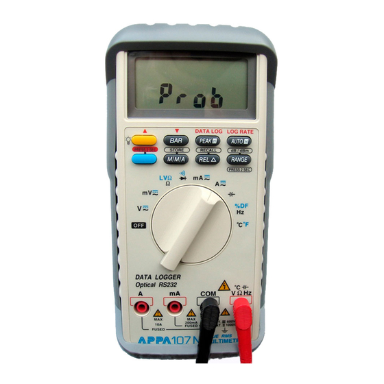
6. SPECIAL FEATURE DESCRIPTIONS 6.1 Auto fuse detection The meter checks the integrity of the internal fuses for the mA, A measure- ments. If an open fuse is detected, ProbE is displayed and beep sounds continuously when the correct function position and probe insertion are applied. 6.2 Probe input guard The meter beeps continuously and displays “ProbE”... -
Page 23: Specifications
8. SPECIFICATIONS All specifications are warranted unless noted typical and apply to the DMM 107N and DMM 109N. Stated accuracies are at 23°C ± 5°C at less than 80% relative humidity and without the battery indicator displayed. 8.1 General specifications... - Page 24 Functions with 4000-count mode divide the [ number of least digits ] by 10 when on 4000 count mode, in addition DCV to add 2 more digits on every ranges. 1. VOLTAGE : 107N 109N 20mV ± (0.06% + 60) ±...
- Page 25 AC + DC Volts : Same as AC(RMS) + 1.00% + 80. Crest Factor : +1.5% addition error for C.F. 1.4 to 3 +3.0% addition error for C.F. from 3 to 4 2. CURRENT : 107N 109N ± (0.20% + 40) ± (0.20% + 40) 20mA, 200mA ±...
- Page 26 3. PEAK HOLD : +[±(0.7% + 20)] additional error for > 20% of full scale and pulse width greater than 0.5mS; ±(10) more for 50% of full scale on 2V range. (2000 / 4000 counts) 4. RESISTANCE : 107N 109N ± (0.30% + 30) ± (0.30% + 30) 200Ω, 2KΩ...
- Page 27 7. CAPACITANCE (4000 counts) (Excludes DIGIT switch) Capacitance 107N 109N ± (1.50% + 10d) ± (1.50% + 10d) 4nF, 40nF ± (0.90% + 5d) ± (0.90% + 5d) 400nF, 4µF 40µF, 400µF ± (1.20% + 5d) ± (1.20% + 5d) 4mF,40mF ±...
- Page 28 8.3 Physical characteristics Characteristics Description 200mmx90mmx42mm Dimensions (H x W x D) 212mmx100mmx55mm(with holster) Weight (with battery) 0.4Kg With holster 0.6Kg 8.4 Environmental characteristics Characteristics Description Temperature operating 0 to + 50°C Non-Operating -20 to + 60°C Humidity (operating) < 80% R.H. Altitude Operating 2,222 m (7290 ft.) Non-Operating...
- Page 29 Certifications and compliances (cont.) Meets the intent of Directive 89/336/EEC for Electtromag- netic Compatibility and Low Voltage Directive 73/23/EEC for Product Safety. Compliance was demonstarted to the following specifications as listed in the official Journal EC Declaration of the European Communites: of Conformity En 55011 Class A : Radiated and Conducted Emissions.
-
Page 30: Maintenance
9. MAINTENANCE Protect the meter from adverse weather conditions. The meter is not waterproof. Do not expose the LCD display to direct sunlight for long period of time. CAUTIONS. To avoid damage to the meter, do not expose it to sprays, liquids, or solvents. - Page 31 Battery and Fuse Replacement Screw Screw Battery Battery Cover Screw Cover Screw Battery Battery Connector Connector Figure 4 Figure 4 9V Battery Battery Top Case Case Fuse 2 Fuse2 15A (600V) 15A(600v) Figure 5 Figure 5 Fuse 1 Fuse1 1A(600v) 1A (600V) Bottom Bottom Case...
-
Page 32: Accessories
10. ACCESSORIES 107N 109N • • Gift Box • • Meter • • Holster + Tilt • • Battery (9V Alkaline) • • Manual • • Test Leads • • Aligator Clip • • Temp. Socket • • K-Type Sensor (50BK) •... - Page 33 APPA TECHNOLOGY CORP. 9F, 119-1 Pao-Zong Rd., Shin-Tien, Taipei, 23115, Taiwan, R.O.C. P.O.Box. 12-24 Shin-Tien, Taiwan. Tel : +886-2-29178820 Fax: +886-2-29170848 E-mail : info@appatech.com Http: // www.appatech.com...
Need help?
Do you have a question about the 107N and is the answer not in the manual?
Questions and answers