Advertisement
Quick Links
Advertisement

Subscribe to Our Youtube Channel
Related Manuals for APPA 98II


Summary of Contents for APPA 98II
- Page 1 DIGITAL MULTIMETER INSTRUCTION MANUAL APPA 98II...
- Page 2 # WARNING THESE SERVICING INSTRUCTIONS ARE FOR USE BY QUALIFIED PERSONNEL ONLY. TO AVOID ELECTRIC SHOCK, DO NOT PERFORM ANY SERVICING OTHER THAN THAT CONTAINED IN THE OPERATING INSTRUCTIONS UNLESS YOU ARE QUALIFIED TO DO SO.
- Page 3 INTRODUCTION 1-1 Unpacking and Inspection Upon removing your new Digital Multimeter from its packing, you should have the following items: 1. Digital Multimeter. 2. Test lead set (one black, one red). 3. Instruction manual. 4. Protective holster.
- Page 4 1-2 Meter Safety Terms as Marked on Equipment. ATTENTION — Refer to manual. DOUBLE INSULATION — Protection Class ¢º. " DANGER — Risk of electric shock. Symbols in this Manual. This symbol indicates where cautionary or other information is found in the manual. FUSE Battery...
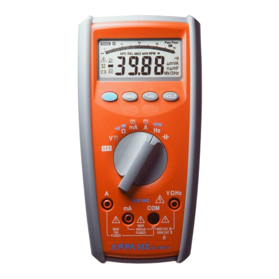
- Page 5 1-3 Front Panel Refer to Figure 1 and to the following numbered steps to familiarize yourself with the meter’s front panel controls and connectors. 1. Digital Display — The digital display has a 4000 counts LCD readout with 82 segments analog bar graph, auto polarity, decimal point, “...
- Page 6 8. Blue Switch — Press the switch to toggle between AC Voltage / Current and DC Voltage / Current in the Voltage / Current mode or to toggle between Resistance and continuity and diode in £[ / /: mode or to toggle between Frequency and RPM in Hz/RPM mode. 9.
- Page 7 Figure 1...
-
Page 8: Specifications
SPECIFICATIONS 2-1 General Specifications Display : The Liquid Crystal Display (LCD) has a maximum reading of 4000 and 82 segments bar graph. Polarity Indication : Automatic, positive implied, negative indicated. Overrange Indication : “OL” or “-OL”. Low Battery Indication : “ “... - Page 9 Dimensions (W x H x D) : 88mm x 180mm x 33.5mm , without holster. 94mm x 188mm x 40mm , with holster. Accessories : Protective Holster , Battery (installed), Test leads and Instruction Manual. 2-2 Environmental Conditions Indoor use. Maximum Altitude : 2000 Meter.
- Page 10 2-3 Electrical Specifications Accuracy is ¡Ó (% reading + number of digits) at 23°C ¡Ó 5°C , less than 80% R.H. (1) DC Volts Over voltage Range Resolution Accuracy protection 400mV 100µV ¡Ó ( 0.25%reading + 5digits) ¡Ó ( 0.4%reading + 1digit) DC 1000V 10mV 400V...
- Page 11 (2) AC Volts Range Resolution Accuracy Over voltage protection 400mV 0.1mV ¡Ó ( 2.0%reading + 10digits) ¡Ó ( 1.3%reading + 5digits) 10mV 750V rms ¡Ó ( 1.3%reading + 5digits) 400V 100mV 40Hz to 1KHz 750V Input Impedance : 10M£[ // less than 100pF. 1.
- Page 12 Crest Factor : +1.5% addition error for C.F. from 1.4 to 3 where C.F. = Peak +3.0% addition error for C.F. from 3 to 4 (3) DC Current Range Resolution Accuracy Voltage Burden 40mA 10µA ¡Ó ( 0.6%reading + 2digits) 200mV max 400mA 0.1mA...
- Page 13 (4) AC Current Range Resolution Accuracy Voltage Burden 40mA 10µA 200mV max ¡Ó ( 2.0%reading + 5digits) 400mA 0.1mA 2V max ¡Ó 10mA (2.5%reading + 5digits) 2V max Frequency Response : 40Hz ~ 1KHz. Overload Protection : 1A (500V) fast blow fuse (10KA breaking capacity @440Vac) for mA input. (size 32¡Ñ...
- Page 14 (5) Resistance Overload Range Resolution Accuracy Protection 400£[ ¡Ó ( 0.7%reading + 3digits) 0.1£[ 4K£[ 1£[ ¡Ó ( 0.4%reading +3digits) 40K£[ 10£[ 600V rms 400K£[ 100£[ ¡Ó ( 0.6%reading + 3digits) 4M£[ 1K£[ ¡Ó ( 1.5%reading + 5digits) 40M£[ 10K£[ Open circuit Voltage : -1.3V approx.
- Page 15 (6) Diode Check and Continuity Max. Test Max. Open Range Resolution Accuracy Current Circuit Voltage ¡Ó ( 1.5%reading + 5digits)* 1.5mA * For 0.4V ~ 0.8V. Overload Protection : 600V rms max. Continuity : Built-in buzzer sounds when resistance is less than 30£[ approximately.
- Page 16 (7) Frequency / RPM Overload Range Resolution Sensitivity Accuracy Protection 4.0KHz/40KRPM 1Hz/30RPM Frequency : 0.01% ¡Ó 1digit 40KHz/400KRPM 10Hz/300RPM 100mV rms 400KHz/4MRPM 100Hz/3KRPM 600V rms 4MHz/40MRPM 1KHz/30KRPM 250mV rms RPM : 0.01% ¡Ó 10digits 40MHz/400MRPM 10KHz/300KRPM 1V rms...
- Page 17 (8) Capacitance Range Resolution Accuracy Overload Protection ¡Ó ( 3%reading + 10digits) 40nF 10pF 400nF 100pF 4µF 600V rms * ¡Ó ( 2%reading + 8digits) 40µF 10nF 400µF 100nF * 4mF 1µF ** ¡Ó ( 5%reading + 20digits) * 40mF 10µF * 4mF and 40mF ranges may have rolling within accuracy.
- Page 18 (9) VAHz Function Range Sensitivity Accuracy 400mV 40mV rms 0.2V rms 2V rms 400V 20V rms 0.01%reading + 5digits 750V 200V rms 40mA 8mA rms 400mA 80mA rms 8A rms...
- Page 19 (10) Auto Power Off (APO) The APO sign on the LCD panel indicates the meter is working in the Auto Power Off mode. If the meter idles for more than 30 minutes, the meter automatically turns the power off. When this happens, the state (non- logic measurement) of the meter is saved, the meter can be turned back on by pressing any switch or changing the rotary switch.
-
Page 20: Operation
OPERATION This instrument has been designed and tested in accordance with IEC Publication 1010, Safety Requirements for Electronic Measuring Apparatus and has been supplied in a safe condition. This instruction manual contains some Information and warnings which have to be followed by the user to ensure safe operation and to retain the instru- ment in safe condition. - Page 21 3-2 Voltage Measurements 1. Connect the red test lead to the “V£[ Hz” input terminal and the other (black) test lead to the “COM ” terminal. 2. Set the rotary function to the V ' position. 3. Measurement of AC voltage can be performed by pushing the “BLUE” key switch. WARNING TO AVOID ELECTRICAL SHOCK, HAZARD OR DAMAGE TO METER, DO NOT A ATTEMPT TO MEASURE VOLTAGE THAT MIGHT EXCEED 1000V ms.
- Page 22 3-3 Current Measurement 1. Connect the red test lead to “mA” terminal and the other (black) test lead to “COM” terminal, or use the “A ” and “COM” terminal in the 10A range. 2. Set function selector rotary switch to “ mA ”...
- Page 23 3-5 Continuity Check by Internal Sounder 1. Connect the red test lead to the “ V£[ Hz” terminal and the other (black) test lead to the “COM ” terminal. 2. Set the rotary function selector to “£[ : ” position. 3.
- Page 24 3-7 Hz / RPM Measurement 1. Connect the red test lead to the “ V£[ Hz ” terminal and the other (black) test lead to the “COM ” terminal. 2. Set the rotary function selector to “Hz RPM” position to measure the frequency or RPM. 3.
-
Page 25: Maintenance
MAINTENANCE # WARNING : TO AVOID ELECTRICAL SHOCK REMOVE TEST LEAD BEFORE OPENING THE COVER. 4-1 General Maintenance 1. Repairs or servicing not covered in this manual should only be performed by qualified personal. 2. Periodically wipe the case with a dry cloth and detergent do not use abrasives or solvents. 4-2 Battery Installation or Replacement The meter is powered by one 9V battery. - Page 26 Screw (i) Battery Cover (ii) 9V Battery Figure 2...
- Page 27 4-3 Fuse Replacement Refer to Figure 3 and the following procedure to examine or replace the meter’s fuse: 1. Perform steps 1 though 3 of the battery replacement procedure. 2. Than remove the two screws from the case bottom and lift the case bottom until it gently unsnaps from the case top.
- Page 28 Bottom Case Rapid Fuse 10A (500V), Radid Fuse 16A (500V), 10KA capacity @ 440 Vac 10KA capacity @ 440 Vac Rapid Fuse 1A (500V), Radid Fuse 1A (500V), 10KA capacity @ 440 Vac 10KA capacity @ 440 Vac Top Case Fuse size is 32mm x 6.3mm Fuse size is 32mm x 6.3mm Figure 3...
- Page 29 HOW TO USE THE PROBE HOLDER Clip one probe on the holder for Wrap the leads around the holster one handed meter operation. to store the test probes.
- Page 30 HOW TO USE THE PROBE HOLDER Swing the stand out for easier meter reading. Swing the upper holder out and hook it over a door.
- Page 31 HOW TO USE THE TILT STAND AND HOLSTER Meter in holster face down. Hang on nail at workbench.
- Page 32 APPA TECHNOLOGY CORP. 9F.119-1 Pao-Zong Rd., Shin-Tien, Taipai, 23115, Taiwan, R.O.C. P.O.Box. 12-24 Shin-Tien, Taiwan. Tel : 886-2-9178820 Fax : 886-2-9170848 e-mail:info @appatech.com http://www.appatech.com Printed In Taiwan Copright 3 2003, APPA Tech., Corp. All rights reserved.
Need help?
Do you have a question about the 98II and is the answer not in the manual?
Questions and answers