Eaton Power Xpert 9395P User And Installation Manual
500 kva / 600 kva
Hide thumbs
Also See for Power Xpert 9395P:
- Installation manual (32 pages) ,
- Mechanical installation manual (31 pages) ,
- Installation and operation manual (239 pages)

Related Manuals for Eaton Power Xpert 9395P


Summary of Contents for Eaton Power Xpert 9395P
- Page 1 Power Xpert™ 9395P UPS 500 kVA / 600 kVA P-164000476 User’s and Installation Guide...
- Page 2 9395P 500kVA / 600 kVA P-164000476 Revision 002 User’s and Installation Guide...
- Page 3 Power Xpert™ 9395P UPS 500 kVA / 600 kVA User’s and Installation Guide 9395P 500kVA / 600 kVA P-164000476 Revision 002 User’s and Installation Guide...
- Page 4 This is a product for commercial and industrial application in the second environment. Installation restrictions or additional measures may be needed to prevent disturbances. ©February 9, 2015 Eaton Corporation All Rights Reserved The contents of this manual are the copyright of the publisher and may not be reproduced (even extracts) unless permission granted.Every care has been taken to ensure the accuracy of the...
-
Page 5: Table Of Contents
Introduction ..................1 1.1 UPS standard features . - Page 6 6.4.2 Normal mode – distributed bypass............. 75 6.4.3 Bypass mode –...
- Page 7 7.5.18 Single UPS restart............... . . 122 7.5.19 UPS and critical load shutdown .
- Page 8 Table 5-7: Recommended installation parts (not supplied by Eaton Corporation)....... .
- Page 9 Figure 3-8. Eaton 9395P 500 kVA / 600 kVA cabinet as shipped on pallet ......
- Page 10 Figure 7-21. Battery Log Detail Screen................. . 94 Figure 7-22.
-
Page 11: Introduction
AC power to protect the customer’s load from power failures. The Eaton 9395P UPS 500 kVA PF 1.0 and 600 kVA PF 0.92 contains two sections: a section configured either as an integrated system bypass module (ISBM) or an Input Output Module (IOM) rated for a maximum of 500/600 kVA and an Uninterruptible Power Module (UPM) section containing two UPMs. -
Page 12: Customer Interface
Figure 1-1. UPS (500 kVA / 600 kVA) with the 7-inch color touchscreen 1.1.3 Customer Interface • Building Alarm Monitoring – Up to five inputs in the UPS are available to connect the facility’s alarm system contacts. Some system configurations may limit the number of inputs available. The UPS uses these inputs to monitor the building alarms in addition to the UPS status. -
Page 13: Advanced Battery Management
1.2.5 Separate rectifier input (factory-installed option) The Eaton 9395P 500 kVA / 600 kVA UPS can be supplied with separate rectifier inputs for each UPM. Separate inputs provide increased flexibility and reliability by allowing multiple input sources to supply the UPS. -
Page 14: Distributed Bypass System
System Bypass Module (SBM) to provide system bypass capabilities. 1.2.8 Inherent redundancy To deliver greater reliability, the Eaton 9395P UPS can be configured by an authorized Eaton Customer Service Engineer for inherent redundancy. When configured, the UPS automatically becomes redundant if the load is at or below the capacity of the UPMs minus the capacity of one UPM. Under normal conditions the UPMs in the UPS share the load equally. -
Page 15: Variable Module Management System And High Alert Modes
a power disturbance. At the end of the time period, the unit defaults back to Energy Saver mode. If the High Alert mode is reactivated during the time period, the timer will be restarted. 1.2.10 Variable Module Management System and High Alert modes NOTE The Variable Module Management System and Energy Saver System modes are mutually exclusive. -
Page 16: Using This Manual
1.4 Using this manual This manual describes how to install and operate the Eaton 9395P 500 kVA / 600 kVA cabinet. Read and understand the procedures described in this manual to ensure trouble-free installation and operation. In particular, be thoroughly familiar with the REPO procedure (see Section “Using the Remote Emergency Power-off Switch”... -
Page 17: For More Information
• Detailed illustrations of the cabinet, including dimension and connection point drawings. Visit www.Eaton.com or contact your service representative for information on how to obtain copies of these manuals. 1.8 Getting help Call your local service representative if help is needed with any of the following: •... - Page 18 9395P 500kVA / 600 kVA P-164000476 Revision 002 User’s and Installation Guide...
-
Page 19: Safety Warnings
2 Safety warnings IMPORTANT SAFETY INSTRUCTIONS SAVE THESE INSTRUCTIONS This manual contains important instructions that should be followed during installation and maintenance of the UPS and batteries. Please read all instructions before operating the equipment and save this manual for future reference. The UPS is designed for computer room applications, and contains safety shields behind the door and front panels. - Page 20 shock is less likely if you disconnect the grounding connection before you work on the batteries. • Proper disposal of batteries is required. Refer to local codes for disposal requirements. • Do not dispose of batteries in a fire. Batteries may explode when exposed to flame. •...
-
Page 21: Ups Installation Plan And Unpacking
6. Have authorized service personnel perform preliminary operational checks and startup. NOTE Startup and operational checks must be performed by an authorized Eaton Customer Service Engineer, or the warranty terms specified on page 123 become void. This service is offered as part of the sales contract for the UPS. -
Page 22: Environmental And Installation Considerations
3.2.1 Environmental and installation considerations The UPS system installation must meet the following guidelines: • The system must be installed on a level floor suitable for computer or electronic equipment. • The system must be installed in a temperature and humidity controlled indoor area free of conductive contaminants. -
Page 23: Table 3-3: Air Conditioning Or Ventilation Requirements During Full Load Operation
Heat rejection Heat rejection Rating/kVA BTU / h x 1000 500 kVA 19.8 67.6 600 kVA 25.5 87.0 Table 3-3: Air conditioning or ventilation requirements during full load operation Ventilation required for cooling air exhaust: approximately 920 liter/sec/250-300kVA unit, + 280 liter/sec (ISBM). -
Page 24: Figure 3-2. Ups Cabinet Dimensions (Right Side View)
Figure 3-2. UPS cabinet dimensions (right side view) Figure 3-3. UPS cabinet dimensions (top view 9395P 500kVA / 600 kVA P-164000476 Revision 002 User’s and Installation Guide... -
Page 25: Figure 3-4. Ups Cabinet Dimensions (Bottom View)
Figure 3-4. UPS cabinet dimensions (bottom view) 9395P 500kVA / 600 kVA P-164000476 Revision 002 User’s and Installation Guide... -
Page 26: Figure 3-5. Ups Cabinet Center Of Gravity
1882 1874 1057 Figure 3-5. UPS cabinet center of gravity 9395P 500kVA / 600 kVA P-164000476 Revision 002 User’s and Installation Guide... -
Page 27: Figure 3-6. Remote Epo Switch Dimensions
Figure 3-6. Remote EPO switch dimensions 1/2 in knockout pattern typ. 5 sides 9395P 500kVA / 600 kVA P-164000476 Revision 002 User’s and Installation Guide... -
Page 28: Ups System Power Wiring Preparation
3.2.2 UPS system power wiring preparation NOTE If installing, as part of the UPS system, a maintenance bypass without a rectifier input breaker, a minimum of two separate feeds with upstream feeder breakers, or one feed with two upstream feeder breakers, must be provided: one for the UPS and one for the maintenance bypass input. DO NOT use one feed or a single feeder breaker to supply both the UPS and the maintenance bypass. -
Page 29: Table 3-5: Separate Rectifier Input Upm Ratings And External Wiring Requirements For The 9395P 500 Kva / 600 Kva
Units Rating 50/60 Hz Basic UPM rating Input voltage Volts 400/400 400/400 AC input to each UPM rectifier (PF 0.99 min) Amps Full load current plus battery recharge current (3) phases, (1) ground Table 3-5: Separate rectifier input UPM ratings and external wiring requirements for the 9395P 500 kVA / 600 kVA Read and understand the following notes while planning and performing the installation: •... -
Page 30: Table 5-6: Ups Cabinet Power Cable Terminations For The 9395P 500 Kva / 600 Kva
Terminals E1 through E12 are 2-hole bus bar mountings. See Table 5-6 for power cable terminations and Table 5-7 for recommended installation parts not supplied by Eaton Corporation. Figure 4-5 on page 37 through Figure 4-9 on page 42 show the location of the power cable terminals inside the UPS. -
Page 31: Table 5-7: Recommended Installation Parts (Not Supplied By Eaton Corporation)
As required As required Table 5-7: Recommended installation parts (not supplied by Eaton Corporation) External overcurrent protection is not provided by this product, but is required by codes. Refer to Table 3-4 and Table 3-5 on page 19 for wiring requirements. If an output lockable disconnect is required, it is to be supplied by the user. -
Page 32: Table 5-9: Recommended Bypass And Output Circuit Breaker Ratings
Table 5-9: Recommended bypass and output circuit breaker ratings There is no DC disconnect device within the UPS. A battery disconnect switch is recommended, and may be required by local codes when batteries are remotely located. The battery disconnect switch should be installed between the battery and the UPS. -
Page 33: Ups System Interface Wiring Preparation
3.2.3 UPS system interface wiring preparation Control wiring for features and options should be connected at the customer interface terminal blocks located inside the UPS as described in Chapter 15: “Installing options and accessories”. WARNING Do not directly connect relay contacts to the mains related circuits. Reinforced insulation to the mains is required. -
Page 34: Distributed Bypass Power Wiring Preparation
3.2.4 Distributed bypass power wiring preparation Read and understand the following notes while planning and performing the installation: • All distributed bypass UPS rectifier inputs must come from one source and all bypass input feeds must come from one source. •... -
Page 35: Inspecting And Unpacking The Ups Cabinet
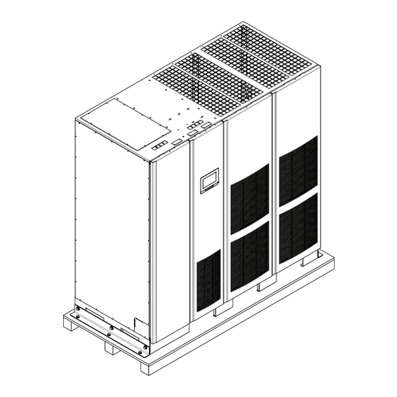
3.3 Inspecting and unpacking the UPS cabinet The UPS cabinet is palleted separately for shipping. The cabinet is shipped bolted to a wooden pallet and protected with outer protective packaging material (see Figure 3-8). WARNING The UPS cabinet is heavy (see Table 3-1 on page 12). If unpacking instructions are not closely followed, the cabinet may tip and cause serious injury and equipment damage. -
Page 36: Figure 3-8. Eaton 9395P 500 Kva / 600 Kva Cabinet As Shipped On Pallet
While waiting for installation, protect the unpacked cabinet from moisture, dust, and other harmful contaminants. Failure to store and protect the UPS properly may void your warranty. Figure 3-8. Eaton 9395P 500 kVA / 600 kVA cabinet as shipped on pallet 9395P 500kVA / 600 kVA... - Page 37 9395P 500kVA / 600 kVA P-164000476 Revision 002 User’s and Installation Guide...
-
Page 38: Ups System Installation
4 UPS system installation 4.1 Preliminary installation information WARNING Installation should be performed only by qualified personnel. Refer to the following while installing the UPS system: • Chapter 3: “UPS installation plan and unpacking” for cabinet dimensions, equipment weight, wiring and terminal data, and installation notes. •... - Page 39 • Insert the forks all the way through the base. DO NOT insert forks partially into the base to move the cabinet. • Fork may be partially inserted into the front or rear fork lift slots for minor positioning if the forks are kept in a horizontal position with no upward angling.
-
Page 40: Figure 4-1. Removing Left Side Shipping Bracket, Isbm And Fi-Upm
Figure 4-1. Removing left side shipping bracket, ISBM and FI-UPM Shipping bracket bolts Removable right front panel Pallet Left side shipping bracket 9395P 500kVA / 600 kVA P-164000476 Revision 002 User’s and Installation Guide... -
Page 41: Figure 4-2. Removing Right Side Shipping Bracket, Isbm And Fi-Upm
Figure 4-2. Removing right side shipping bracket, ISBM and FI-UPM Top screw Removable left front panel Front door Bottom screws Pallet Right side shipping bracket Shipping bracket bolts 9395P 500kVA / 600 kVA P-164000476 Revision 002 User’s and Installation Guide... -
Page 42: Field Installed Upm (Fi-Upm) Installation
4.3 Field installed UPM (FI-UPM) installation If installing a system with Field Upgrade UPM, install the FI-UPM using the instructions in the Eaton 9395P Field Installed UPM Mechanical Installation Manual, listed in section 1.8 on page 10. After the FI- UPM is installed, proceed to Section 4.4 if installing a battery system;... -
Page 43: Figure 4-3. Distributed Bypass Wire Length
Figure 4-3. Distributed bypass wire length NOTE Required parallel system wiring length must be equal to ensure approximately equal current sharing when in Bypass mode. For proper operation the following must be true: 1A = 2A = 3A = 4A 1B = 2B = 3B = 4B In order to save cabling costs, the following is also considered to be sufficient: 1A+1B=2A+2B=3A+3B=4A+4B... -
Page 44: Installing Ups External And Battery Power Wiring
4.6 Installing UPS external and battery power wiring NOTE The UPS cabinet is shipped with a debris shield covering the ventilation grill on top of the unit. Do not remove the debris shield until installation is complete. However, remove the shield before operating the UPS. -
Page 45: Figure 4-4. Conduit And Wire Entry Locations
Figure 4-4. Conduit and wire entry locations Exhaust grill debris shield (Remove covering before operating system.) Top entry conduit landing for AC input and output, and DC input (Remove panel to drill or punch cable entry holes.) Interface entry for TB1 through TB3 wiring and X-Slot connections (Remove panels to drill or punch cable entry holes.) Bottom entry conduit landing for AC input and output, and DC input (remove panel to drill or punch cable entry holes.) -
Page 46: Figure 4-5. Ups Power Terminal Locations - Part A The Terminals In The Circle Are Not Included In Iom Units
Figure 4-5. UPS power terminal locations - part a The terminals in the circle are not included in IOM units. 9395P 500kVA / 600 kVA P-164000476 Revision 002 User’s and Installation Guide... - Page 47 NOTE UPS power terminal locations - part bA unit with separate rectifier feeds has two sets of rectifier AC input connections. 9395P 500kVA / 600 kVA P-164000476 Revision 002 User’s and Installation Guide...
-
Page 48: Figure 4-6. Ups Power Terminal Locations - Separate Rectifier Feed
15704.0209 15704.0209 Figure 4-6. UPS power terminal locations - separate rectifier feed 9395P 500kVA / 600 kVA P-164000476 Revision 002 User’s and Installation Guide... -
Page 49: Figure 4-7. Front View
Figure 4-7. Front view Rectifier input Load output Not in use By-pass input Battery + Neutral Battery 9395P 500kVA / 600 kVA P-164000476 Revision 002 User’s and Installation Guide... -
Page 50: Battery Wiring
Chapter 23: “Product specifications” for maximum battery charger current. To install wiring to connections: 1. If using an Eaton battery cabinet, proceed to Step 2; otherwise, proceed to Step 5. 2. Route and connect the battery cables between the UPS and the battery cabinets in accordance with the instructions in the Eaton 9395P Integrated Battery Cabinet (Model IBC-L) installation manual. -
Page 51: Installing Interface Connections
4.7 Installing interface connections WARNING Hazardous voltages are present near the user interface terminal area if the UPS is not totally disconnected. 4.7.1 TB1, TB2, and TB3 connections (other than TB1 battery interface connections) NOTE Interface wiring must be installed from the top of the UPS cabinet. To install wiring to connections: 1. -
Page 52: Figure 4-8. Typical Alarm Relay Connection
Figure 4-8. Typical alarm relay connection NOTE Alarm relay contacts have a maximum current rating of 5A and a switched voltage rating of 30 Vac and 28 Vdc. Alarm relay normally-open and normally-closed return terminals are separated on the terminal board, but are connected together. -
Page 53: Figure 4-9. Interface Terminal Locations
Figure 4-9. Interface terminal locations X-slot communication bays TB1 and TB2 Protective cover panels Control panel AC input breaker CB1 9395P 500kVA / 600 kVA P-164000476 Revision 002 User’s and Installation Guide... - Page 54 For TB1, TB2 and TB3 connector assignments, see Figure 4-10 and for detail AA, see Figure . The X-Slot communication bays are illustrated in Figure 4-12. NOTE Interface terminal detail AA X-Slot communication bays 9395P 500kVA / 600 kVA P-164000476 Revision 002 User’s and Installation Guide...
-
Page 55: Figure 4-10. Terminal Blocks Tb1, Tb2, And Tb3 Connector Assignments
Figure 4-10. Terminal blocks TB1, TB2, and TB3 connector assignments Remote EPO NC Alarm relay return Remote EPO return Alarm relay NO Remote EPO NO Alarm relay return Remote EPO return Building alarm 1 Battery aux Building alarm 1 return Battery aux return Building alarm 2 Battery shunt trip +... - Page 56 NOTE All building alarm inputs require an isolated normally-open or normally-closed contact or switch (rated at 24 Vdc, 20 mA minimum) connected between the alarm input and common terminal as shown. Building alarm inputs can be programmed for use with either normally-open or normally-closed contacts.
-
Page 57: Tb1 Battery Interface Connections
Step10. Route the Shunt trip and Aux wiring harness supplied with the battery cabinet from the battery cabinet to the UPS cabinet. Refer to the Eaton 9395P Integrated Battery Cabinet (Model IBC-L) installation manual for battery cabinet wiring access information. -
Page 58: X-Slot Connections
When installing internal wiring to X-Slot terminals, route the wiring through the internal opening in the X-Slot communication bay. For installation and setup of an X-Slot card, please contact Eaton Corporation. To install wiring to connections: 1. If not already installed, install the LAN and telephone drops. -
Page 59: Figure 4-12. X-Slot Communication Bays
Figure 4-12. X-Slot communication bays X-Slot communications bay 1 X-Slot communications bay 2 X-Slot communications bay 3 X-Slot communications bay 4 9395P 500kVA / 600 kVA P-164000476 Revision 002 User’s and Installation Guide... -
Page 60: Installing A Remote Epo Switch
This switch must be a dedicated switch not tied into any other circuits. This procedure is intended to be used for the installation of the Eaton remote EPO switch. If installing another manufacturer’s switch, only use this procedure as a guide. -
Page 61: Table 4-2: Remote Epo Wire Terminations
To customer interface From remote EPO switch Remarks Terminal board TB1 in UPS cabinet TB1-4 TB1-3 Twisted wires (2) 2... 0.75mm 2.5mm TB1-5 TB1-4 Table 4-2: Remote EPO wire terminations Figure 4-14. Normally-open remote EPO switch wiring NOTE Remote EPO switch rating is 24 Vdc, 1 A minimum. Remote EPO normally-open and normally-closed return terminals are separated on the terminal board, but are connected together. -
Page 62: Figure 4-15. Normally-Closed Remote Epo Switch Wiring
Figure 4-15. Normally-closed remote EPO switch wiring NOTE Remote EPO switch rating is 24 Vdc, 1 A minimum. Remote EPO normally-open and normally-closed return terminals are separated on the terminal board, but are connected together. Figure 4-16. Normally closed and normally open remote EPO switch wiring NOTE Remote EPO switch rating is 24 Vdc, 1 A minimum. -
Page 63: Installing Options, Accessories, And Distributed Bypass Control Wiring
4.10 Initial startup Startup and operational checks must be performed by an authorized Eaton Customer Service Engineer, or the warranty terms specified on page 123 become void. This service is offered as part of the sales contract for the UPS. Contact service in advance (usually a two-week notice is required) to reserve a preferred startup date. -
Page 64: Installing Options And Accessories
5 Installing options and accessories 5.1 Installing an optional HotSync CAN Bridge Card As an option, a HotSync Controller Area Network (CAN) Bridge Card, shown in Figure 5-1, can be installed to provide connectivity for operational mode control of a parallel system. In addition, this card can be used to connect optional system monitoring devices, such as a Remote Monitor Panel II, a Relay Interface Module II, or a Supervisory Contact Module II, to the UPS. -
Page 65: Table 5-1: Hotsync Can Bridge Card Interface Connections
To locate the appropriate terminals on the HotSync CAN Bridge Card, see Figure 5-2 and Table 5-1 on page 55. Figure 5-2. HotSync CAN Bridge Card connections Connections for Parallel Systems Control Connections for RPM II, RIM II, or SCM II Connections for Bypass Status Alarm J3 Terminal... -
Page 66: Installing Distributed Bypass Control Wiring
NOTE Setup of the HotSync CAN Bridge Card for parallel operation must be performed by an authorized Eaton Customer Service Engineer. Contact an Eaton service representative to schedule a date. 12. Reinstall the protective cover panel and secure with the cabinet mounted screws. -
Page 67: Figure 5-3. Distributed Bypass System Can And Pull-Chain Simplified Interface Wiring
Figure 5-3. Distributed bypass system CAN and Pull-Chain simplified interface wiring NOTE This drawing is for distributed bypass wiring purposes and is not a floor layout plan. UPSs can be placed in any physical order. Figure 5-4. Distributed bypass system UPS CAN wiring without MOBs NOTE External CAN connections between UPSs require shielded twisted pair wire. -
Page 68: Table 5-2: Can Bridge Card Wiring Terminations
J3-10 (Shield) J3-10 (Shield) J3-10 (Shield) J3-10 (Shield) Table 5-2: CAN Bridge Card wiring terminations Figure 5-5. Distributed bypass Pull-Chain wiring without MOBs NOTE Use twisted pair wiring between the UPS and MOB AUX contacts. From UPS 1 To UPS 2 To UPS 3 (if installed) To UPS 4 (if installed) TB2-1... -
Page 69: Figure 5-6. Distributed Bypass Pull-Chain Wiring With Mobs
Figure 5-6. Distributed bypass Pull-Chain wiring with MOBs NOTE NC and NO designations on MOB AUX contacts are defined with breaker in OFF (open) position. If MOB contacts have pigtail leads, use the same wire gauge to connect to the UPS and use the correct crimp connections for the wire gauge. -
Page 70: Table 5-4: Pull-Chain Wiring Terminations With Mobs
Always confirm contact operation prior to wiring. From Function UPS 1 CAN Bridge Card J3-1 (Alarm) MOB 1 Aux 1 NC MOB Open Alarm UPS 1 CAN Bridge Card J3-2 (Alarm MOB 1 Aux 1 Com Return) UPS 1 TB2-1 (Pull Chain) MOB 1 Aux 2 NO Pull Chain UPS 1 TB2-2 (Pull Chain Common) -
Page 71: Understanding Ups Operation
6 Understanding UPS operation 6.1 Looking inside the UPS system The Eaton 9395 UPS is a continuous-duty, solid-state, transformerless (at 400 Vac), three-phase, true online system that provides conditioned and uninterruptible AC power to the UPS system’s output and critical load. The basic system consists of a rectifier, battery converter, inverter, monitoring/operation control panel, integrated communication server, and digital signal processor (DSP) logic. -
Page 72: Single Ups
UPS to successfully support its applied loads. 6.2.1 Modes The Eaton 9395 UPS supports a critical load in five different modes of operation. The UPS can automatically use all five modes, as required. NOTE The Variable Module Management System and Energy Saver System modes are mutually exclusive. -
Page 73: Figure 6-2. Path Of Current Through The Ups In Normal Mode
Figure 6-2. Path of current through the UPS in normal mode During normal UPS operation, power for the system is derived from a utility input source through the rectifier input contactor K1. The front panel displays Normal, indicating the incoming power is within voltage and frequency acceptance windows. -
Page 74: Bypass Mode
6.2.3 Bypass mode The UPS automatically switches to bypass mode if it detects an overload, load fault, or internal failure. The bypass source supplies the commercial AC power to the load directly. Figure 6-3 shows the path of electrical power through the UPS system when operating in Bypass mode. CAUTION The critical load is not protected while the UPS is in Bypass mode. -
Page 75: Variable Module Management System
6.2.4 Variable Module Management System NOTE VMMS and ESS modes are mutually exclusive. If VMMS mode is enabled, ESS mode is disabled. In VMMS mode, the UPS operates as a traditional double-conversion UPS. However, the UPS will selectively shift the load to fewer UPMs based on the required load in order to force the remaining UPMs to carry a higher load. -
Page 76: Battery Mode
Figure 6-4. Path of current through the UPS in Energy Saver System If the bypass source falls outside of a predetermined voltage or frequency window, the system forward transfers to Battery mode and then to Normal mode with the inverter assuming the load. The transfer takes place with a 2 ms typical transfer time, to ensure loads being fed by the system output are not interrupted. -
Page 77: Figure 6-5. Path Of Current Through The Ups In Battery Mode
Figure 6-5. Path of current through the UPS in battery mode During a utility power failure, the rectifier no longer has an AC utility source from which to supply the DC output current required to support the inverter. The input contactor K1 opens and the battery instantaneously supplies energy to the battery converter. -
Page 78: Ups System Oneline Configurations
6.3 UPS system oneline configurations The system oneline drawings in this section show the simplified internal structure of the UPS, battery supply, and basic maintenance bypass. Voltage Oneline drawing UPS model System type Input Output Figure 6-6 on 9395P-600 kVA Single Reverse Transfer UPS - Two UPM, Common Rec- page 69 9395P-500 kVA... -
Page 79: Figure 6-6. Ups System - Common Rectifier Feed, Common Battery, Dual-Feed Configuration
Figure 6-6. UPS system – common rectifier feed, common battery, Dual-Feed configuration *) Static Switch line not present in IOM configuration systems. 9395P 500kVA / 600 kVA P-164000476 Revision 002 User’s and Installation Guide... -
Page 80: Figure 6-7. Ups System - Common Rectifier Feed, Separate Battery, Dual-Feed Configuration
Figure 6-7. UPS system – common rectifier feed, separate battery, Dual-Feed configuration *) Static Switch line not present in IOM configuration systems. 9395P 500kVA / 600 kVA P-164000476 Revision 002 User’s and Installation Guide... -
Page 81: Figure 6-8. Ups System With A Field Upgrade Upm - Common Rectifier Feed, Common Battery, Dual-Feed Configuration
Figure 6-8. UPS system with a Field Upgrade UPM – common rectifier feed, common battery, Dual-Feed configuration 9395P 500kVA / 600 kVA P-164000476 Revision 002 User’s and Installation Guide... -
Page 82: Figure 6-9. Ups System With A Field Upgrade Upm - Common Rectifier Feed, Separate Battery, Dual-Feed Configuration
Figure 6-9. UPS system with a Field Upgrade UPM – common rectifier feed, separate battery, Dual-Feed configuration 9395P 500kVA / 600 kVA P-164000476 Revision 002 User’s and Installation Guide... -
Page 83: Figure 6-10. Simplified Dual-Feed Ups With Maintenance Bypass Panel
Figure 6-10. Simplified Dual-Feed UPS with maintenance bypass panel NOTE If installing a maintenance bypass, a minimum of two separate feeds with upstream feeder breakers, or a single feed with two upstream feeder breakers, must be provided: one for the UPS or rectifier input breaker (RIB) (if installed) and one for the maintenance bypass input. -
Page 84: Multiple Ups Distributed Bypass System
The system is paralleled for capacity if all UPMs in a system are required to support the load. 6.4.1 Multiple UPS parallel system modes Similar to the single UPS system, the Eaton 9395 UPS parallel system supports a critical load in five different modes of operation. The standard operation modes are: NOTE The Variable Module Management System and Energy Saver System modes are mutually exclusive. -
Page 85: Normal Mode - Distributed Bypass
The UPSs continually monitor themselves and the incoming utility power and automatically switch between these modes as required, without operator intervention, except when manually switching to Bypass mode. The sophisticated detection and switching logic inside the UPSs ensures that operating mode changes are automatic and transparent to the critical load, while internal monitoring systems indicate the current mode of operation. -
Page 86: Bypass Mode - Distributed Bypass
6.4.3 Bypass mode – distributed bypass In Bypass mode, the output of the system is provided with three-phase AC power directly from the bypass input. While in this mode, the output of the system is not protected from fluctuations, spikes, or power outages from the source. -
Page 87: Battery Mode - Distributed Bypass
In the Parallel Redundant (N+1) arrangement, the bypass circuitry in each UPS operates to support the applied loads on bypass. If the UPSs are in NORMAL and one UPS trips offline, the remaining UPSs do not go to bypass as long as they have the capacity to support the load. In the Parallel Capacity (N+0) arrangement, if one UPS trips offline and goes to bypass, the remaining UPSs also go to bypass, if remaining UPSs can not support the load 6.4.4 Battery mode –... -
Page 88: Multiple Ups Distributed Bypass System Oneline Configurations
6.5 Multiple UPS distributed bypass system oneline configurations The distributed bypass system oneline drawings in this section show the simplified internal structure of the UPS, battery supply, and basic maintenance bypass in a multiple UPS configuration. These onelines do not show each UPM in the UPSs, but represent each UPS in the distributed bypass system. The internal structure of each UPS is shown in Figure 6-6 through Figure 6-9 starting on page 77. -
Page 89: Figure 6-14. Typical Distributed Bypass System (1+1 And 2+0 Configurations)
Figure 6-14. Typical distributed bypass system (1+1 and 2+0 configurations) 9395P 500kVA / 600 kVA P-164000476 Revision 002 User’s and Installation Guide... -
Page 90: Figure 6-15. Typical Distributed Bypass System (2+1 And 3+0 Configurations)
Figure 6-15. Typical distributed bypass system (2+1 and 3+0 configurations) 9395P 500kVA / 600 kVA P-164000476 Revision 002 User’s and Installation Guide... -
Page 91: Figure 6-16. Typical Distributed Bypass System (3+1 And 4+0 Configurations)
Figure 6-16. Typical distributed bypass system (3+1 and 4+0 configurations) 9395P 500kVA / 600 kVA P-164000476 Revision 002 User’s and Installation Guide... -
Page 92: Ups Operating Instructions
The controls and indicators identified and described in this section are used to control and monitor UPS operation. Figure shows the UPS controls and indicators. Figure 7-1. Eaton 9395 500 kVA UPS controls and indicators Control panels AC input breaker CB1 (optional) -
Page 93: Control Panel
7.1.1 Control panel The control panel is used to set up and control the UPS, and to monitor UPS operation. For a description of the UPS control panel functions, see Section . 7.1.2 Circuit breakers The optional circuit breaker (CB1) is used to control the AC input to the UPS rectifier. CB1 has three positions: ON, OFF and tripped. -
Page 94: Color Touchscreen Control Panel
7.2 Color Touchscreen Control Panel This section describes how the various screens are used to control and monitor UPS operation. The following figure shows the location of the optional color touchscreen control panel (1) on the front door of the UPS. For a description of the control panel, see Section 7 .3 “Using the Color Touchscreen Control Panel”... -
Page 95: Using The Color Touchscreen Control Panel
7.3 Using the Color Touchscreen Control Panel The following sections describe the UPS control panel and how to monitor and control UPS operation. Figure 7-3. UPS Color Touch screen Control Panel (Typical) The color touchscreen control panel consists of: • A color liquid crystal touch screen display (1) •... -
Page 96: Using The Touch Screen
(see Figure “Sign In or Password Request Screen”). Figure 7-4. Parts of the Touch Screen A The UPS status area automatically displays the Eaton model number, current time and date, active alarms, active notices, and load percent and battery run time for the UPS. If the Environmental Monitoring Probe is installed, the temperature and humidity sensed by the probe will also be displayed. -
Page 97: Using The Main Menu Buttons
The small head symbol between the system model and time allows the operator select a different language from an imbedded list. The top line of the display blinks while scrolling when the system needs attention. Some notices and alarms may be accompanied by an audible horn. To silence the horn, touch anywhere on the control panel once. -
Page 98: Power Maps Screen (Online Mode)
Menu Option Description POWER MAPS Allows operator to observe system power flow. LOGS Allows access to system information logs. STATISTICS Allows access to see system specific operation values. SETTINGS Allows access to various screen controlled variables for system operation. Level 0, 1 and 2 are for user/operator. Level 3 is used only by service person- nel. -
Page 99: Figure 7-7. Main Menu And Power Maps Screen (Online Mode)
Number 3) refers to Figure “Consumption Screen from Home Screen” . Figure 7-7. Main Menu and Power Maps Screen (Online Mode) Touching the LOAD kVA button displays the Output kVA screen shown in the following figure. Figure 7-8. Output kVA Screen from Home Screen Touching the AVERAGE EFFICIENCY button displays the system efficiency screen shown in the following figure. -
Page 100: Power Maps Screen (Bypass Mode)
Figure 7-10. Consumption Screen from Home Screen 7.3.5 Power Maps Screen (Bypass Mode) The following figure shows the Bypass screen. The Bypass screen displays only when the system is in Bypass mode. The Bypass screen shows a real-time graphical representation of the operating status. Touching any of the buttons on the right side of the screen takes the user directly to that information screen. -
Page 101: Meters Summary Screen
Figure 7-12. Typical Command Confirmation Screen (Charger Off) 7.3.7 Meters Summary Screen The following figure shows the Meters Summary screen. This screen allows selection of the various metering readout functions of Input, Output and overall System status. The three left items in the OVERVIEW section of the screen are not active buttons but are status detail panels. -
Page 102: Figure 7-14. Input Meters Screen
Figure 7-14. Input Meters Screen The Bypass Meters Screen shown in the following figure displays values pertaining to the Bypass conditions. Figure 7-15. Bypass Meters Screen The Output Meters Screen shown in the following figure displays values pertaining to the system output. -
Page 103: Input Meters Detail Screen
7.3.9 Input Meters Detail Screen The following figure shows the Input Meters detail screen. This screen displays the individual values of the system in additional detail. The Bypass, Output, and Battery meters screens display similar values relevant to their monitoring of the system. -
Page 104: Figure 7-19. Battery Meters Screen
Figure 7-19. Battery Meters Screen Figure 7-20. Battery Log Screen The following figures show the Battery Log Detail screen and the Battery Log Summary screen. Figure 7-21. Battery Log Detail Screen 9395P 500kVA / 600 kVA P-164000476 Revision 002 User’s and Installation Guide... -
Page 105: System Events Main Screen
Figure 7-22. Battery Log Summary Screen 7.3.11 System Events Main Screen When the UPS system is running in Online mode, it continually monitors itself and the incoming utility power. In Battery or Bypass modes, the UPS may issue alarms to display exactly what event caused the change from Online mode. -
Page 106: System Status Screen And Controls
• System Event Messages - When a system event occurs, a message appears on the LCD in the UPS status area. This message is also written to the Active Events Log and may be added to the History Log. The messages are divided into four categories: alarms, notices, status, and commands. -
Page 107: Figure 7-26. System Status Screen
Figure 7-26. System Status Screen The following figure shows the Module Controls screen. This screen allows control of the individual modules within the system. It also gives their values and status. Figure 7-27. Module Controls Screen The following figure shows the Module Control Detail screen. By selecting any of the modules shown on the previous screen, the user can observe full details of an individual module. -
Page 108: Figure 7-28. Module Control Detail Screen
Figure 7-28. Module Control Detail Screen The Metering Method screen allows the operator to select line-to-line or line-to-neutral monitoring values. See the following figures. Figure 7-29. Online Mode Metering Method Option Screen Number 1) in the following figure points to an icon that indicates an Event (System or Bypass). 9395P 500kVA / 600 kVA P-164000476 Revision 002... -
Page 109: Settings Screen
Figure 7-30. Bypass Mode Metering Method Option Screen 7.3.14 Settings Screen The screen shown in the following figure gives the operator access to basic system information such as serial number, installed firmware version, etc. Touching the CLEAN SCREEN button disables the screen for 30 seconds to allow the user to safely clean the screen without affecting operation. -
Page 110: Energy Advantage Architecture (Eaa) Screen
Figure 7-32. Configuration Options Screen 7.3.16 Energy Advantage Architecture (EAA) Screen This screen shown in the following figure allows the operator to activate the various energy saving and power efficiency modes of the system. The various Energy Advantage Architecture operations are described in Section 1.2.9 and in Section 1.2.10. -
Page 111: Statistics Basic Screen
Figure 7-34. Disable ESS Screen The screen shown in the previous figure asks the operator to verify disabling the ESS mode running at that time. Figure 7-35. High Alert Timer Screen The screen shown in the figure above asks the operator if they want to start the High Alert mode timer. 7.3.17 Statistics Basic Screen The screen shown in the following figure allows the operator to query the system for various operational statistics such as shown in the second figure (“Statistics Data Detail Screen”) in this... -
Page 112: Ess Comparison Screen
Figure 7-36. Statistics Basic Screen Figure 7-37. Statistics Data Detail Screen 7.3.18 ESS Comparison Screen The screen shown in the following figure allows the operator to visually obtain EAA mode efficiency values. Figure 7-38. ESS Comparison Screen 9395P 500kVA / 600 kVA P-164000476 Revision 002 User’s and Installation Guide... -
Page 113: Ups Module Map Screen
7.3.19 UPS Module Map Screen The screen shown in the following figure allows the operator to control the individual UPMs. Figure 7-39. UPS Module Map Screen 7.3.20 System Overview Screen The screen shown in the following figure displays values for all UPS and UPM parameters. Figure 7-40. -
Page 114: Ups Operation Using The Color Touchscreen Control Panel
Panel NOTE The Energy Saver System mode commands are displayed only if installed at the factory or by an Eaton Customer Service Engineer. NOTE The Variable Module Management System and Energy Saver System modes are mutually exclusive. If the Variable Module Management System mode is enabled, the Energy Saver System mode commands will not be displayed. -
Page 115: Starting The Ups In Bypass Mode
UPS to achieve Online mode. The Online status indicator is illuminated. The UPS status indicates ONLINE on the header section of the screen. The UPM status indicates ONLINE, CHARGING on the MIMIC Screen. To activate or enable/disable any of the UPS operational modes, follow the online screen prompts. To obtain any system information, follow the on screen prompts to get to the proper screen. -
Page 116: Starting A Single Upm
NOTE The Variable Module Management System mode commands are displayed only if enabled at the factory or by an Eaton Customer Service Engineer. The Variable Module Management System and Energy Saver System modes are mutually exclusive. If the Energy Saver System mode is enabled, the Variable Module Management System mode commands will not be displayed. -
Page 117: Disable Variable Module Management System Mode From The Eea Controls Menu
EEA controls menu To start High Alert mode: NOTE The High Alert mode commands are displayed only if enabled at the factory or by an Eaton Customer Service Engineer. The Variable Module Management System and Energy Saver System modes are mutually exclusive. -
Page 118: Transfer From Normal To Bypass Mode
5. The High Alert Timer is now running (default time is 1 hour) and during this time the UPS will not enter ESS or VMMS modes. After the timer has expired the alarm will clear and the UPS once again transfer to ESS / VMMS modes. 7.4.8 Transfer from Normal to Bypass mode To transfer the critical load to Bypass mode, perform the following procedure: CAUTION... -
Page 119: Disable Energy Saver System From Eaa Controls Menu
NOTE The Energy Saver System commands are displayed only if enabled at the factory or by an Eaton Customer Service Engineer. Press the LOCK icon on the main screen. The Sign In screen is displayed. Use operator password to log in (factory default password is 0101). -
Page 120: Transfer From Normal To Bypass Mode And Shut Down Ups
7.4.13 Transfer from Normal to Bypass mode and shut down UPS To transfer the critical load to Bypass mode and shut down the UPS, perform the following procedure: Transfer the critical load to bypass by performing the procedure in Section 7.3.11. 2. -
Page 121: Charger Control
2. Perform the LOAD OFF procedure in Section 7 .4.18. The input, output, and bypass backfeed contactors open, the battery breaker or disconnect is tripped, and the power module is turned off. WARNING Power is present inside the UPS cabinet until the upstream input feeder circuit breaker is opened. -
Page 122: Using The Remote Emergency Power-Off Switch
NOTE The following instructions are for the Eaton Corporation-supplied REPO switch. If a customer- supplied REPO switch is used, it may not activate in the same manner; refer to the operating instructions provided with the switch. -
Page 123: Figure 7-41. The Normal Positions Of The Mbs Switches And Rectifier Disconnect Switch (Must Be Located In The Site Wiring)
NOTE The integral MBS and Static Bypass need to supplied by the same source. Figure 7-41. The normal positions of the MBS switches and rectifier disconnect switch (must be located in the site wiring) Turn UPS from normal mode to mechanical bypass The procedure to turn the UPS to mechanical bypass switch is described below. - Page 124 Turn UPS from mechanical bypass to normal mode The procedure to turn the UPS back to normal mode is described below. 1. The normal start position should be the following: 2. Turn ON rectifier switch to connect rectifier input to UPS. 3.
-
Page 125: Multiple Ups Distributed Bypass Operation
7.5 Multiple UPS distributed bypass operation 7.5.1 Starting the distributed bypass system in normal mode To start the distributed bypass system: Unfasten the front door latches and swing the doors open on all of the UPS. If the UPSs contain input breakers (CB1), verify that all input breakers are open. -
Page 126: Enable Variable Module Management System Mode From The Eea Controls Menu
5. Close all UPS Bypass input feeder circuit breakers. 6. Close the doors and secure the latches. Observe the UPS control panel displays becoming active, indicating logic power. 8. On any UPS, press the LOCK icon on the main screen. The Sign In screen is displayed. Use operator password to log in (factory default password is 0101). -
Page 127: Starting A Single Upm
NOTE To transfer to Normal mode after starting individual UPMs, follow the procedure in Section 7.5.9. 7.5.7 Starting a single UPM To start a single UPM: Unfasten the front door latch and swing the door open. 2. If the UPS contains input breaker CB1, verify that input breaker CB1 is open. 3. -
Page 128: Transfer From Bypass To Normal Mode
To transfer the critical load to Energy Saver System: NOTE The Energy Saver System commands are displayed only if enabled at the factory or by an Eaton Customer Service Engineer. On any UPS, press the LOCK icon on the main screen. The Sign In screen is displayed. Use the op- erator password to log in (factory default password is 0101). -
Page 129: Transfer From Energy Saver System To Bypass Mode
To transfer the critical load to Bypass mode: NOTE The Energy Saver System commands are displayed only if enabled at the factory by an Eaton Customer Service Engineer. On any UPS, press the LOCK icon on the main screen. The Sign In screen is displayed. Use operator password to log in (factory default password is 0101). -
Page 130: Single Upm Restart
5. To turn of the previously chosen power module, select SHUT DOWN UPM again. Command confirmation pop-up screen will show up asking confirmation for the action. Select YES. The UPM opens its input contactor and goes to SHUTDOWN. The power module is turned off. The remaining UPMs continue to supply the critical load. -
Page 131: Single Ups Shutdown Using Upm Shutdown
WARNING Power is present inside the UPS cabinet until the upstream input feeder circuit breaker is opened. NOTE If the UPS contains an input breaker (CB1), DO NOT open the breaker unless no input feeder breaker is installed. 9. Open the input and bypass feeder circuit breakers for the UPS being shut down. The UPS is now completely shut down. -
Page 132: Single Ups Restart
WARNING Power is present inside the UPS cabinet until the upstream input feeder circuit breaker is opened. NOTE If the UPS contains an input breaker (CB1), DO NOT open the breaker unless no input feeder breaker is installed. 10. Open the input and bypass feeder circuit breakers for the UPS being shut down. The UPS is now completely shut down. -
Page 133: Ups And Critical Load Shutdown
7.5.19 UPS and critical load shutdown To perform maintenance or service on the critical load, shut down power to the load: Turn off all equipment that is being powered by the distributed bypass system. 2. Transfer the UPSs to bypass by performing the procedure in Section 7 .5.11. 3. -
Page 134: Using The Remote Emergency Power-Off Switch
NOTE The following instructions are for the Eaton-supplied REPO switch. If a customer-supplied REPO switch is used, it may not activate in the same manner; refer to the operating instructions provided with the switch. - Page 135 1. Firmly push the red pushbutton until it locks into place. The switch latches into the activated state. The input, output, and bypass backfeed contactors open, the battery breaker or disconnect is tripped, and the power module is turned off immediately, without asking for verification on all UPSs.
-
Page 136: Communication
Figure 4-4 on page 36 and Figure 4-9 on page 44 through Figure 4- 11 on page 46. 8.1 X-Slot cards The Eaton 9395P UPS has four X-Slot communication bays (see Figure 4-9 on page 44 for bay locations). The UPS is compatible with the following X-Slot cards (see Figure 8-1): •... -
Page 137: Lansafe Power Management Software
Industrial relay card 8.2 LanSafe Power Management Software Each Eaton 9395P UPS ships with LanSafe® Power Management Software. To begin installing LanSafe software, see the instructions accompanying the Software Suite CD. LanSafe software uses an RS-232 serial link to communicate with the UPS. The software provides up- to-date graphics of UPS power and system data and power flow, a complete record of critical power events, and notification of important UPS or power information. -
Page 138: Display Ups Control Panel
In Terminal mode, the user can request the following: • [ESC] [A] displays the Active Alarms. • [ESC] [H] displays the Event History. • [ESC] [N] displays the Node Bits Setup. • [ESC] [V] displays the UPS control panel. • [ESC] [Q] Quit. - Page 139 If a port is operating in Terminal mode and is connected to a computer, you can press [Esc] [H] to print the entire log with a firmware version header. The log in terminal mode is always in english. MODEL: Eaton 9395P CTO: TF12710000000 SERIAL: MCU DSP:70.81.14...
-
Page 140: Building Alarm Monitoring
103 NOTICE: INVERTER L2 CURRENT LIMIT (PM1) 104 NOTICE: INVERTER L3 CURRENT LIMIT (PM1) 8.4 Building alarm monitoring This standard feature lets you connect the UPS to your building alarms, such as smoke detectors or overtemperature alarms. The customer interface terminals for external connections are located inside the UPS. -
Page 141: Ups Maintenance
9 UPS maintenance The components inside the UPS cabinet are secured to a sturdy metal frame. All repairable parts and assemblies are located for easy removal, with very little disassembly. This design allows authorized service personnel to perform routine maintenance and servicing quickly. You must schedule periodic performance checks of your UPS system to keep it running properly. -
Page 142: Performing Preventive Maintenance
9.2 Performing preventive maintenance The UPS system requires very little preventive maintenance. However, the system should be inspected periodically to verify that the units are operating normally and that the batteries are in good condition. 9.2.1 DAILY maintenance Perform the following steps daily: 1. -
Page 143: Installing Batteries
A basic training course, available from Eaton Corporation, gives you a competent working knowledge of the UPS system operation and teaches you how to perform first level corrective maintenance. For more information about training and other services, contact the Eaton Help Desk for Eaton products. 9395P 500kVA / 600 kVA... -
Page 144: Product Specifications
10 Product specifications 10.1 Model numbers The UPS systems are housed in free-standing cabinets with safety shields behind the doors. The UPS systems are available in 50/60 Hz with various output power ratings. Models Power Rating Frequency 9395P 500 kVA 500 kVA PF 1.0 50/60 Hz 9395P 600 kVA... -
Page 145: Environmental
Output Voltage Balance 3% for 100% maximum load imbalance (linear load) Output Voltage Phase Displacement 3° for 100% maximum load imbalance (linear load) Output Transients ±5% for 100% load step or removal Frequency Regulation ±0.1 Hz free running Synchronous to Bypass Bypass within voltage limits of +5%, –8% of output setting;... -
Page 146: Warranty
11 Warranty The product is warranted against defects in design, materials and workmanship for a period of twelve (12) months from its original date of purchase. The local office or distributor may grant a warranty period different to the above and refer to local terms of liability as defined in the supply contract. The UPS manufacturer is not responsible for •... -
Page 147: Installation Checklist
Accessories are mounted in installed locations and wiring is terminated inside the UPS cabinet. (OPTIONAL) The debris shield covering the UPS cabinet ventilation grill is removed. Startup and operational checks are performed by an authorized Eaton Customer Service Engineer. 9395P 500kVA / 600 kVA...
Need help?
Do you have a question about the Power Xpert 9395P and is the answer not in the manual?
Questions and answers