Eaton Power Xpert 9395P Mechanical Installation Manual
Field installed upm
Hide thumbs
Also See for Power Xpert 9395P:
- User and installation manual (147 pages) ,
- Installation manual (32 pages) ,
- Installation and operation manual (239 pages)
Table of Contents
Advertisement
Quick Links
Advertisement
Table of Contents

Related Manuals for Eaton Power Xpert 9395P


Summary of Contents for Eaton Power Xpert 9395P
- Page 1 Power Xpert™ 9395P Field Installed UPM P-16400478 Mechanical Installation Manual...
- Page 3 Power Xpert™ 9395P Field Installed UPM Mechanical Installation Manual...
- Page 4 Eaton is a registered trademark of Eaton Corporation or its subsidiaries and affiliates. ©Copyright 2008–2014 Eaton Corporation, Raleigh, NC, USA. All rights reserved. No part of this document may be reproduced in any way without the express written approval of Eaton Corporation.
-
Page 5: Table Of Contents
Introduction ..................1 1.1 Using This Manual . - Page 7 Figure 3-7. Eaton 9395P FI-UPM Cabinet as Shipped on Pallet .......
-
Page 9: Introduction
Service Engineer, or the warranty terms specified on page 23 become void. This service is offered as part of the sales contract for the FI-UPM. Contact an Eaton service representative in advance (usually a two-week notice is required) to request service. -
Page 10: Symbols, Controls, And Indicators
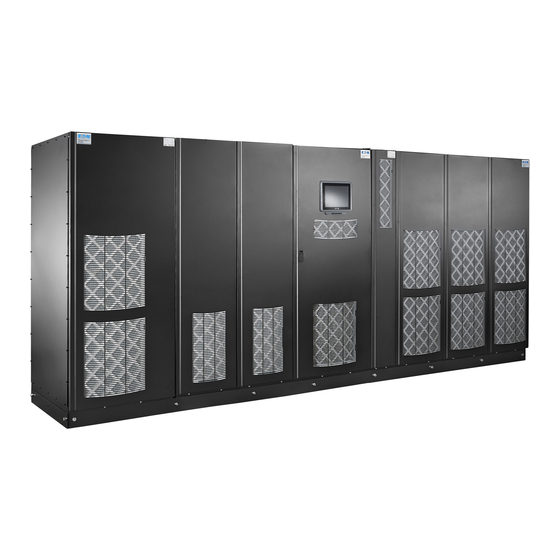
Figure 1-1. Eaton 9395P Field Installed UPM 1.3 Symbols, controls, and indicators The following are examples of symbols used on the UPS or accessories to alert you to important information:... -
Page 11: For More Information
• Communication capabilities of the UPS system. Visit www.eaton.com/power quality or contact Eaton service representative for information on how to obtain copies of these manuals. 1.5 Getting Help If help is needed with any of the following: •... - Page 12 • Regional locations and telephone numbers • A question about any of the information in this manual • A question this manual does not answer Please call your local service representative.
-
Page 13: Safety Warnings
2 Safety warnings IMPORTANT SAFETY INSTRUCTIONS SAVE THESE INSTRUCTIONS This manual contains important instructions that should be followed during installation of the Field Installed UPM (FI-UPM). Read all instructions before operating the equipment and save this manual for future reference. The FI-UPM cabinet is designed for industrial or computer room applications, and contains safety shields behind the panel. -
Page 15: Field Installed Upm Installation Plan And Unpacking
Service Engineer, or the warranty terms specified on page 23 become void. This service is offered as part of the sales contract for the FI-UPM. Contact an Eaton service representative in advance (usually a two-week notice is required) to request service. - Page 16 Model Shipping Installed Eaton 9395P FI-UPM Table 3-1: FI-UPM Cabinet Weight The FI-UPM cabinet uses forced air cooling to regulate internal component temperature. Air inlets are in the front of the cabinet and outlets are in the top. Allow clearance in front of and above each cabinet for proper air circulation.
-
Page 17: Figure 3-1. Fi-Upm Cabinet Dimensions (Front View; Dimensions Are In Millimeters [Inches])
1871.5 [73.7] [28.8] Figure 3-1. FI-UPM Cabinet Dimensions (Front View; dimensions are in millimeters [inches]) 831.5 39.5 [32.7] [1.6] 149.2 [5.9] 192.4 [7.6] [34.3] Figure 3-2. FI-UPM Cabinet Dimensions (Right Side View, dimensions are in millimeters [inches]) -
Page 18: Figure 3-3. Fi-Upm Cabinet Dimensions (Top View; Dimensions Are In Millimeters [Inches])
475.4 [1.4] [18.7] [1.5] 758.8 [20] Figure 3-3. FI-UPM Cabinet Dimensions (Top View; dimensions are in millimeters [inches]) [8.4] 602.8 [23.7] Figure 3-4. FI-UPM Cabinet Dimensions (Bottom View; dimensions are in millimeters [inches]) [33.4] [31.8] 59.2 [28.7] [2.4] 39.2 [1.54] [2.7] [13.6] [32.7]... -
Page 19: Inspecting And Unpacking The Fi-Upm Cabinet
1871.5 [73.7] [36.4] [17.1] [11.8] [32.7] [28.8] Figure 3-6. FI-UPM Cabinet Center of Gravity (dimensions are in millimeters [inches]) 3.3 Inspecting and Unpacking the FI-UPM Cabinet The FI-UPM cabinet is palleted separately for shipping. The cabinet is shipped bolted to a wooden pallet and protected with outer protective packaging material (see Figure 3-7). - Page 20 CAUTION Do not install a damaged cabinet. Report any damage to the carrier and contact an Eaton service representative immediately. NOTE For the following step, verify that the forklift or pallet jack is rated to handle the weight of the cabinet (see Table 3-1 on page 8 for cabinet weight).
-
Page 21: Figure 3-7. Eaton 9395P Fi-Upm Cabinet As Shipped On Pallet
Figure 3-7. Eaton 9395P FI-UPM Cabinet as Shipped on Pallet... -
Page 23: Field Installed Upm Installation
4 Field Installed UPM Installation 4.1 Preliminary Installation Information WARNING Installation should be performed only by qualified personnel. Refer to the following while installing the Field Installed UPM (FI-UPM): • Chapter 3 for cabinet dimensions, equipment weight, wiring and terminal data, and installation notes. -
Page 24: Figure 4-1. Removing The Left Side Shipping Bracket
1. If not already accomplished, use a forklift or pallet jack to move the cabinet to the installation area, or as close as possible, before unloading from the pallet. If possible, move the cabinet using the pallet. Insert the forklift or pallet jack forks from the right side of the pallet (facing the cabinet), be- tween the supports on the bottom of the pallet (see Figure 3-6 on page 11 for the FI-UPM cabinet center of gravity measurements). -
Page 25: Mechanical Installation
Figure 4-2. Removing the Right Side Shipping Bracket FI-UPM Removable Front Panel Pallet Right Side Shipping Bracket Shipping Bracket Bolts 4.3 Mechanical Installation To mechanically install the FI-UPM: 1. Remove the wire entry plate located on the bottom left side of the UPS cabinet (see Figure 4-3). 2. -
Page 26: Figure 4-3. Ups Cabinet Wire Entry Plate And Knockout Locations (Left Side View)
NOTE A flat cabinet joining bracket is provided for securing the cabinets at the top front (see Step 7). 6. Remove and retain one top screw and two bottom screws securing the FI-UPM front panel (see Figure 4-2). Lift the panel straight up to remove it from the panel hanger bracket at the top of the cabinet. -
Page 27: Electrical Installation
UPS, and FI-UPM battery terminals will be installed by an Eaton Customer Service Engineer. This service is offered as part of the sales contract for the FI-UPM. Contact an Eaton service representative in advance (usually a two-week notice is required) to request service. - Page 29 A 230 Vac service outlet (depending on local mains voltage) is located within 7.5 meters of the UPS equip- ment. The debris shield covering the FI-UPM cabinet ventilation grill is removed. Startup and operational checks are performed by an authorized Eaton Customer Service Engineer.
- Page 30 Notes...
-
Page 31: Warranty
Warranty The product is warranted against defects in design, materials and workmanship for a period of twelve (12) months from its original date of purchase. The local office or distributor may grant a warranty period different to the above and refer to local terms of liability as defined in the supply contract. The UPS manufacturer is not responsible for •...
Need help?
Do you have a question about the Power Xpert 9395P and is the answer not in the manual?
Questions and answers