Raven SCS 460 Installation & Service Manual
Hide thumbs
Also See for SCS 460:
- Installation & service manual (58 pages) ,
- Installation and service manual (50 pages) ,
- Operator's manual (47 pages)

Related Manuals for Raven SCS 460


Summary of Contents for Raven SCS 460
- Page 1 SCS 460 Installation & Service Manual P/N 016-0159-479 Rev K 09/15 Copyright 2009, 2015...
- Page 2 N O T I C E The use of the suspension type fertilizers and lime slurries will significantly reduce the life of the plastic parts in the Flow Meter and motorized Control Valve. Check the rotor and inlet hub assembly in the Flow Meter frequently for worn parts. Excessive wear can affect accuracy.
-
Page 5: Table Of Contents
SYMBOL DEFINITION .............................. 3 INTRODUCTION ............................... 4 INSTALLATION ................................. 5 1. MOUNTING THE RAVEN RADAR SPEED SENSOR ......5 2. MOUNTING THE FLOW METER ........... 6 3. MOUNTING THE CONTROL VALVE ........6 4. MOUNTING THE CONSOLE AND CABLING ........7 BATTERY CONNECTIONS ............................ -
Page 6: Symbol Definition
SYMBOL DEFINITION - Gallons per minute - Centimeters lit/min - Liters per minute - Decimeters dl/min - Deciliter per minute - Meter - Pounds per square inch - Miles per hour - Kilopascal - Kilometers - Gallon per acre km/h - Kilometers per hour lit/ha - Liter per hectare... -
Page 7: Introduction
The motorized Control Valve and Flow Meter mount to the framework supporting the boom valves. Appropriate cabling is furnished for field installation. The operator sets the target volume per area to be sprayed and the SCS 460 automatically maintains the flow regardless of vehicle speed or gear selection. A manual override switch allows the operator to manually control flow for system check-out and spot spraying. -
Page 8: Installation
INSTALLATION MOUNTING THE RAVEN RADAR SPEED SENSOR See Appendix 1 for Wheel Drive Speed Sensor installation instructions. See Appendix 2 for Speedometer Drive Speed Sensor installation instructions. For mounting the radar, the following guidelines will assure proper installation: It is suggested that a large heavy mounting bracket, (P/N 107-0159-693) be attached to the vehicle frame for mounting the radar. -
Page 9: Mounting The Flow Meter
MOUNTING THE FLOW METER Mount Flow Meter in the area of the boom valves per Figure 4. All flow through Flow Meter must go to booms only, i.e., no return line to tank or pump after Flow Meter. Mount Flow Meter horizontal to the ground. Use the bracket to secure the Flow Meter. -
Page 10: Mounting The Console And Cabling
FIGURE 5 FIGURE 5 NOTE: The SCS 460 Control Console is designed to be used with external boom switches. In order for the Console to know when and which boom signal wires are provided. The Console recognizes a boom ON whenever +12 VDC is applied to the boom signal wire. -
Page 11: Battery Connections
FIGURE 6 FIGURE 6 NOTE: Disconnect SCS 460 battery wires if the system is not used for an extended period, (i.e. two weeks). With the POWER switch to OFF, the system draws .25 milliamps of current to maintain information stored in Console... -
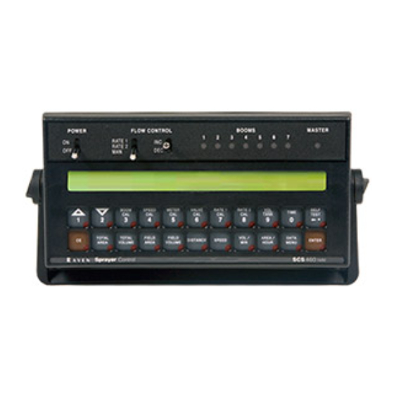
Page 12: Console Features
CONSOLE FEATURES IMPORTANT: This Console requires selection of US (acres), SI [hectares], or TU {1,000 sq. ft.} area; SP1 (wheel drive, etc.) or SP2 (radar) speed sensor; and C-Sd (Standard Valve), C-F (Fast Valve), or C-FC (Fast Close Valve). Console Revision can be determined by the letter stamped in REV box on label. -
Page 13: Console Calibration
CONSOLE CALIBRATION CALCULATING "BOOM CAL" Broadcast Spraying Calculate the width of each boom in inches [cm] by multiplying the number of tips times the spacing. Write these boom widths down for future reference when programming the Console. FIGURE 7 Band Spraying Calculate the width of each boom in inches [cm] by multiplying the number of tips by the spacing. -
Page 14: Calculating "Speed Cal
CALCULATING "SPEED CAL" Initial SPEED CAL is 598 [152]. Complete Steps 1 thru 6 to refine this number after "INITIAL CONSOLE PROGRAMMING" has been completed. Set POWER switches to ON, all other switches to OFF. Enter "0" in key labelled: Drive 1 mile [1 kilometer]. -
Page 15: Calculating "Valve Cal
CALCULATING "VALVE CAL" The initial Control Valve calibration number for VALVE CAL is 2123 for C-Sd (standard valve), or 743 for C-F (fast valve) and C-FC (fast close valve). The VALVE CAL number is used to control response time of the Motor Control to the change in vehicle speed. -
Page 16: Calculating "Rate 1 And Rate 2 Cal
CALCULATING "RATE 1 AND RATE 2 CAL" Determine the application rate at which your chemical should be sprayed. Consult with your Dealer to ensure your spray nozzles are capable of applying at this rate. In determining which spray nozzles to use with your sprayer, you must know: 1) Nominal Application Pressure ___ PSI [kpa] 2) Target Application Rate... -
Page 17: Console Programming
CONSOLE PROGRAMMING When entering data into the Console, the entry sequence is always the same. NOTE: DATA MUST BE ENTERED FOR ALL BOOMS. ENTER "0" IF BOOM IS NOT USED. DATA MUST ALSO BE ENTERED IN KEYS 3 THRU 8. Depress the key in which Depress the ENTER key. -
Page 18: Initial Console Programming
INITIAL CONSOLE PROGRAMMING When you first turn on Console power, after all installation procedures have been completed, the Console will flash "CAL" in the RATE display. This means you must "calibrate", or program, the Console before it can be operated. This is a one- time operation which does not have to be repeated. - Page 19 Display C-Sd (Standard Valve), C-F (Fast Valve), or C-FC (Fast Close Valve). Depressing momentarily steps the DATA display from C-Sd to C-F. Depressing momentarily steps the DATA display from C-F to C-FC. Depressing momentarily steps the DATA display from C-FC to C-Sd. Selecting C-Sd, C-F, or C-FC.
- Page 20 NOTE: RATE 2 should not be more than 20% different from RATE 1 or else spray pattern may suffer. YOU HAVE NOW COMPLETED PROGRAMMING THE CONSOLE The flashing "CAL" will now extinguish. If not, repeat procedure starting at Step 9. ENTERING ADDITIONAL DATA: You may wish to enter data in the keys labelled although it is not...
- Page 21 Enter TIME Select TIME Enter TIME when RATE display shows "TInE". NOTE: This is a 24 hour clock. Therefore, all time after 12:59 p.m., add 12 hours. Thus, 8:30 a.m. is entered as 8:30, but 1:30 p.m. is entered as 13:30 in the keyboard.
-
Page 22: Other Display Features
OTHER DISPLAY FEATURES To display TOTAL AREA covered, momentarily depress key labelled: To "zero out" this total at any time, enter a "0" in this key. To display TOTAL VOLUME sprayed, momentarily depress key labelled: To "zero out" this total at any time, enter a "0" in this key. To display FIELD AREA covered, momentarily depress key labelled: To "zero out"... -
Page 23: Volume/Minute Rate Fault
VOLUME/MINUTE RATE FAULT Depress until DATA display flashes. A low limit flow rate may now be entered. If the actual volume per minute falls below this limit, the Control Valve stops closing, an alarm sounds, and the display flashes "-LL-". The low limit value should be determined with all booms ON. -
Page 24: Control Valve Delay
CONTROL VALVE DELAY Depress until DATA display flashes. The first digit, ( X 0 0 0 ), is the Control Valve delay digit. This feature allows the user to set a delay between the time the booms are turned ON and when the Console begins to control the flow rate. -
Page 25: 12. Data Menu
(Serial interface console only). FILE GPS FILE REFERENCE Used only with Raven Grid Application System. See Grid Application System manual for more details (Serial inter- face console only). InAC GPS OPTIONS Used only with Raven Grid Application System. - Page 26 DISPLAY RATE DATA FEATURE and DESCRIPTION bAUd 1200 BAUD RATE Used in GPS mode and data logging mode. Selectable between 1200 or 9600 baud (Serial interface console only). TriG DATA LOGGER TRIGGER VALUE Used in data logging mode. The trigger determines how often actual rate data string (See Appendix 9 for data communi- cation string formats) is sent to the serial port.
- Page 27 AUDIBLE ALARM ON/OFF RATE display will show "ALrn". DATA display will show "on". Depressing momentarily changes the DATA display between "on" and "off". A value of "on" means the audible alarms are enabled; a value of "off" means the audible alarms are disabled. Momentarily depress to advance to DISPLAY SMOOTHING ON/OFF.
- Page 28 GPS OPTIONS GPS is inactive when the RATE display shows "GPS" and the DATA display shows "InAC". The GPS features are explained further in the GRID APPLICATION SYSTEM MANUAL. Momentarily depress to advance to FIELD REFERENCE. FIELD REFERENCE RATE display will show "FrEF". DATA display will show "0".
- Page 29 DATA LOGGER ON/OFF The DATA LOGGER uses the communications strings listed in Appendix 9 to pass data out through the serial port. The data is sent at a set time interval or a set distance traveled, as determined by the values entered in the DATA LOGGER TRIGGER VALUE and DATA LOGGER TRIGGER UNITS.
-
Page 30: 13. Decimal Shift
13. DECIMAL SHIFT The DECIMAL SHIFT feature is used to increase system accuracy at low application rates. Shifting of the decimal point is done during the entry of METER CAL. After entering METER CAL mode, depress the decimal shift key labelled , enter the meter calibration constant number, and depress . -
Page 31: Initial System Set-Up
INITIAL SYSTEM SET-UP Fill tank with water only. (If positive displacement pump is used, open pressure relief valve, PRV). Place MASTER ON/OFF switch to ON and BOOM ON/OFF switches to OFF. Place RATE 1/RATE 2/MAN switch to MAN. Place POWER ON/OFF switch to ON. Verify that Boom Widths, SPEED CAL, METER CAL, VALVE CAL, and RATE CALS have been entered correctly into the Console. -
Page 32: Initial System Field Test
INITIAL SYSTEM FIELD TEST Drive down field or road at target speed with sprayer booms off, to verify SPEED readout on Console. Turn on sprayer and booms and place the RATE 1/RATE 2/MAN switch to RATE 1. Increase or decrease speed by one MPH [2 km/h]. The system should automatically correct to the target application rate. -
Page 33: Troubleshooting Guide
TROUBLESHOOTING GUIDE CORRECTIVE ACTION PROBLEM 1) Check fuse on back of Console. 1) NO DISPLAY LIGHTS WITH POWER ON. 2) Check battery connections. 3) Check operation of POWER ON/OFF switch. 4) Return Console to your Dealer to replace Processor Board Assembly. 1) Return Console to your dealer to 2) ALL KEYBOARD LIGHTS ON AT SAME replace Face Plate Sub-assembly. - Page 34 2) Remove one red magnet and one black magnet from the wheel. (Reposition remaining red and black magnets directly across from each other). Enter a SPEED CAL number in the Console twice as large as the correct SPEED CAL number. speed check on hard surface road.
- Page 35 4) If problem persists, return Console to Dealer to replace Processor Board Assembly. 15) CAN NOT VARY RATE IN MANUAL 1) Check cabling to motorized Control OPERATION OR IN AUTO. Valve for breaks. 2) Check connections in cabling for cleanliness. 3) Verify that there is voltage at the valve connector by placing MASTER switch ON;...
-
Page 36: Appendixes
APPENDIX 1 WHEEL DRIVE SPEED SENSOR INSTALLATION AND CALIBRATION PROCEDURE MOUNTING WHEEL DRIVE SPEED SENSOR The Wheel Drive Speed Sensor consists of four magnets, a switch assembly with cable, and mounting hardware. Sequence of mounting Speed Sensor: Select a non-driven wheel (left front tractor wheel or implement wheel). Check for predrilled holes in rim. - Page 37 RIM DRILLING INSTRUCTIONS FOR WHEEL DRIVE SPEED SENSOR MAGNETS On wheels which do not have pre-punched mounting holes, proceed as follows: RIMS WITH FOUR OR EIGHT HOLE STUD PATTERN: Choose stud holes that are opposite each other as shown below. Using the center of opposite holes, scribe two lines on the rim web to divide the circumference into four equal parts.
- Page 38 CALCULATING "SPEED CAL" Place a chalk mark or tape onto the vehicle tire that the Speed Sensor mounted to it as shown below. Mark the initial spot on the ground. Drive vehicle straight ahead counting 10 full revolutions of the wheel. The mark must stop at the same position it was in when the vehicle started.
-
Page 39: Speedometer Drive Speed Sensor Installation
APPENDIX 2 SPEEDOMETER DRIVE SPEED SENSOR INSTALLATION AND CALIBRATION PROCEDURE MOUNTING THE SPEEDOMETER DRIVE SPEED SENSOR Remove the existing speedometer cable from the back of the vehicle speedometer. Pull cable through fire wall into engine compartment. Install adapter and key on speedometer cable and connect to Transducer Assembly. (Some units do not use adapter and key). - Page 40 CALCULATING "SPEED CAL" Complete "INITIAL CONSOLE PROGRAMMING" before doing this procedure. Enter “0” in key labelled Enter a SPEED CAL of 612 [155] in key labelled Drive 1 mile [1 km]. CAUTION: Do not use vehicle odometer to determine distance. Use section lines or Highway markers.
-
Page 41: Alternate By-Pass Line Plumbing System
APPENDIX 3 ALTERNATE BY-PASS LINE PLUMBING SYSTEM FIGURE 11 FIGURE 11 FIGURE 11 FIGURE 11 FIGURE 11 INITIAL SYSTEM SET-UP Plumb the system as shown in Figure 11. Adjust as follows: Install Polarity Reversal Jumper in motorized Control Valve Cable (P/N 115-0159-415). Fill tank with water only. - Page 42 Verify that each boom valve operates and that no nozzles are plugged by operating the BOOM ON/OFF switches. Place all BOOM ON/OFF switches to ON. Hold the FLOW CONTROL switch to INC position for approximately 12 seconds. This assures motorized Control Valve is fully closed. (Pressure gauge is not supplied). Adjust agitator line hand valve for desired agitation.
-
Page 43: Procedure To Test Speed Sensor Extension Cables
APPENDIX 4 PROCEDURE TO TEST SPEED SENSOR EXTENSION CABLES Verify that the Console is in the SP1 Speed Sensor mode while testing the cable. Disconnect extension cable from Speed Sensor Assembly cable. Hold extension cable connector so that keyway is pointing in the 12 o’clock position. PIN DESIGNATIONS 2 o’clock socket location is power. -
Page 44: Procedure To Test Flow Meter Cables
APPENDIX 5 PROCEDURE TO TEST FLOW METER CABLES Disconnect cable from Flow Sensor. Hold Flow Sensor cable so that the keyway is pointing in the 12 o’clock position: PIN DESIGNATIONS 2 o’clock socket location is ground. 10 o’clock socket location is power. 6 o’clock socket location is signal. -
Page 45: Flow Meter Maintenance And Adjustment Procedure
APPENDIX 6 FLOW METER MAINTENANCE AND ADJUSTMENT PROCEDURE Remove Flow Meter from sprayer and flush with clean water to remove any chemicals. WARNING: Thoroughly bleed nurse tank hose and all other system lines prior to disassembling the Flow Meter, fittings, and hoses. Remove flange bolts or clamp from the Flow Meter. -
Page 46: Procedure To Re-Calibrate Flow Meter
APPENDIX 7 PROCEDURE TO RE-CALIBRATE FLOW METER Enter a METER CAL number of 10 [38] in the key labelled Enter a TOTAL VOLUME of 0 in the key labelled Switch OFF all booms. Remove a boom hose and place it into a calibrated 5 gallon [19 liter] container. Switch ON appropriate boom switch (for the hose that was just placed into the 5 gallon container) and the MASTER switch. -
Page 47: Serial Interface
Line Feed Communication Carriage Return string RATE 1 Rate Cal = 123.4 Decimal point is not sent from Remote Computer to Raven Console. Optional 9 pin to 9 pin cable pinout (P/N 115-0159-822). DSR 6 CTS 8 RAVEN DTR 4 COMPUTER/... -
Page 48: Scs 460 Communication Strings
APPENDIX 9 SCS 460 COMMUNICATION STRINGS REMOTE COMPUTER TO SCS 450/460 CONSOLE All request strings begin with $R, to indicate a Raven communication string. Rate 1 Change Request: $R,RC,<rate_1_cal><CR><LF> Calibration String Values Request: $R,CR<CR><LF> Data String Request: $R,DR<CR><LF> SCS 450/460 CONSOLE TO REMOTE COMPUTER... - Page 49 063-0159-946 Display Board Spacer 107-0159-478 LCD Display Board 064-0159-428 Processor Board 064-0159-570 Processor Board (Serial Interface) 064-0159-572 Connector Plate Assembly 063-0159-948 Connector Plate Assembly (Serial Interface) 063-0171-255 Back Assembly 063-0159-530 SCS 460 Console 063-0159-938 SCS 460 Console (Serial Interface) 063-0171-249...
- Page 51 How Can I Get Service? Bring the defective part and proof of purchase to your Raven Dealer. If your Dealer agrees with the warranty claim, the Dealer will send the part and proof of purchase to their distributor or to Raven Industries for final approval.
Need help?
Do you have a question about the SCS 460 and is the answer not in the manual?
Questions and answers