Raven SCS 450 Installation & Service Manual
Hide thumbs
Also See for SCS 450:
- Installation and service manual (50 pages) ,
- Installation manual (13 pages)
Table of Contents
Advertisement
Advertisement
Table of Contents
Troubleshooting

Related Manuals for Raven SCS 450


Summary of Contents for Raven SCS 450
- Page 1 Installation & Service Manual SCS 450 Serial Interface...
- Page 2 Raven Industries shall not be held responsible or liable for the effects of atmospheric conditions and sunspot activity on the performance of our products. Raven Industries cannot guarantee the accuracy, integrity, continuity, or availability of the GPS signal from the U.S.
-
Page 3: Table Of Contents
Calibration Card..............11 Introduction ..........................11 Chapter 4 Installation................13 Sensor Installation ........................13 Raven Radar Speed Sensor ....................13 Wheel Drive Speed Sensor ....................14 Phoenix 10 GPS Speed Sensor ..................16 Flow Meter Installation ......................17 Mounting the Flow Meter .................... - Page 4 ..................... 45 Speed Sensor Cables ......................46 Testing Speed Sensor Extension Cables ................46 Troubleshooting ........................47 Console Issues ........................47 Rate Control Issues ......................48 Chapter 8 Replacement Parts ............... 51 SCS 450 Serial Interface Installation & Service Manual...
-
Page 5: Important Safety Information
Do not operate the SCS 450 Serial Interface system while under the influence of alcohol or an illegal substance. • Remain in the operator’s position in the machine at all times when the SCS 450 Serial Interface system is engaged. •... -
Page 6: Hydraulic Safety
CAUTION Hydraulic Safety • Raven Industries recommends that appropriate protective equipment be worn at all times when working on the hydraulic system. • Never attempt to open or work on a hydraulic system with the equipment running. Care should always be taken when opening a system that has been previously pressurized. -
Page 7: Chapter 2 Introduction
SCS 450 also functions as an area monitor, speed monitor, and volume totalizer. The operator sets the target volume per area to be applied, and the SCS 450 automatically maintains the flow. A manual override switch allows the operator to manually control the flow for spot-spraying. The actual volume per area being applied is displayed at all times on the console. -
Page 8: Unit Definitions And Conversions
1 kPa = 0.145 psi • 1 meter (m) = 3.281 feet • 1 kilometer (km) = 0.621 miles • 1 inch = 25.4 mm or 2.54 cm • 1 mile = 1.609 km SCS 450 Serial Interface Installation & Service Manual... -
Page 9: Calculating Machine's Calibration Values
Calculate the Speed Cal Value Raven Radar Only The initial Speed Cal value for Raven radar is 598 [152]. After the initial console programming has been performed, this value may be adjusted to optimize the system’s performance. Manual No. 016-0159-831... - Page 10 After calculating the Speed Cal value, the number must be adjusted according to the actual number of magnets used. For Example: Normal Number of Magnets Calculated Speed Cal Adjusted Speed Cal Actual Number of Magnets 1200 SCS 450 Serial Interface Installation & Service Manual...
-
Page 11: Calculate The Meter Cal Value
Introduction Calculate the Meter Cal Value No calculation of the Meter Cal value is necessary, since the flow meter calibration value is stamped on the tag attached to each flow meter. Locate this number and write it down for future reference when programming the console. -
Page 12: Calculate The Rate 1 And Rate 2 Cal Values
Calculate the Rate 1 and Rate 2 Cal Values Determine the application rate at which the chemical is to be sprayed, and then consult with your Raven dealer to verify that the spray nozzles are capable of applying at that rate. To determine which spray nozzles to use... -
Page 13: Verifying Flow Rate Limits
35 - 1,800 GPM [132.48 - 6813 lit/min] Krohne 6” Magmeter* 70 - 3,000 GPM [264.95 - 11,355 lit/min] *Note: Only Krohne Magmeters sold through Raven Industries should be used with Raven controllers. No other Krohne Magmeters are supported. Manual No. 016-0159-831... - Page 14 Chapter 2 SCS 450 Serial Interface Installation & Service Manual...
-
Page 15: Calibration Card
C alibration Card CHAPTER C h a p t e r 3 Introduction Located on the next page is a card that may be used to record the machine’s calibration values. Write the calibration numbers in pencil so that they may be revised if necessary. Cut on the dotted line, fold, and insert the card into the plastic envelope provided for your convenience. - Page 16 Chapter 3 SCS 460 Serial Interface Installation & Service Manual...
-
Page 17: Installation
C h a p t e r 4 Sensor Installation Raven Radar Speed Sensor Note: Raven Industries recommends the installation of a large, heavy mounting bracket (P/N 107-0159- 693) on the machine’s frame for mounting the radar speed sensor. Radar Mounting Locations FIGURE 1. -
Page 18: Wheel Drive Speed Sensor
Measure in one inch from the rim on each end of the lines and mark the wheel at each point. Drill a 1/2” hole on each of the four marks. Note: The distance between each set of drilled holes must be equal within 1/8” [3 mm] to ensure system accuracy. SCS 450 Serial Interface Installation & Service Manual... - Page 19 Installation Rim Drilling for Six Hole Wheel Stud Patterns - Optional This section is required only on wheels that do not have pre-punched mounting holes. If your machine has the pre-punched mounting holes, proceed to the Mounting the Wheel Drive Speed Sensor section on the following page.
-
Page 20: Phoenix 10 Gps Speed Sensor
Turn off all equipment on the machine to avoid interference with the speed sensor setup. Apply power to the speed sensor by connecting the white wire to a clean ground and the red wire to a clean switched power source. SCS 450 Serial Interface Installation & Service Manual... -
Page 21: Flow Meter Installation
Installation Flow Meter Installation Mounting the Flow Meter Flow Meter Installation Diagram FIGURE 8. Note: All flow through the flow meter must go to the boom sections only. Ensure there are no return, agitation, or sparge lines to the tank or pump after the flow meter. Mount the flow meter in the area of the boom valves (horizontal to the ground) using the supplied bracket. -
Page 22: Control Valve Installation
Install the control valve on the main hose line between the flow meter and the booms, with the motor in the upright position. Refer to the diagram above. Connect the yellow and green 2-pin connector of the flow control cable to the control valve. SCS 450 Serial Interface Installation & Service Manual... -
Page 23: Alternate Bypass Line Plumbing System
Installation Alternate Bypass Line Plumbing System Alternate Bypass Line Plumbing System Diagram FIGURE 10. Note: This plumbing schematic applies only to applications of less than 3 GPM [11 lit/min]. For flow of 3 GPM [11 lit/min] or greater, the motorized control valve is installed on the main hose line. Refer to the Install the Control Valve section on page 18 for the main hose line plumbing procedure. -
Page 24: Console And Cabling Installation
Mount the SCS 450 console to a secure area inside the machine’s cab. Note: The SCS 450 console should be mounted in the machine’s cab so that the machine operator has easy access to it. Connect the female end of the console control cable into the back of the console. - Page 25 Installation Console Cabling Diagram FIGURE 11. Manual No. 016-0159-831...
-
Page 26: Install The Remote Switch - Optional
The master switch on the console can be used again once the remote switch is turned off. Refer to the figure above to install the optional remote switch. SCS 450 Serial Interface Installation & Service Manual... -
Page 27: Battery Connections
If the system will not be used for an extended period of time (for example, two weeks), be sure to disconnect the SCS 450 battery wires. If the wires are not disconnected and the SCS 450 is only turned OFF, the system will continue to draw 0.25 milliamperes of current to maintain information stored in the console computer, draining the battery. - Page 28 Chapter 4 SCS 450 Serial Interface Installation & Service Manual...
-
Page 29: Console Programming And Calibration
Calibration Important: The SCS 450 console requires the selection of volume rate (US, SI, or TU), speed sensor type (SP1 or SP2), and valve type (C-SD - standard valve, C-F - fast valve, C-FC - fast close valve, C-P - PWM valve, or C-PC - PWM close valve). Hold the SELF TEST key to review the selections. -
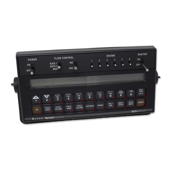
Page 30: Console Features
Chapter 5 Console Features SCS 450 Serial Console FIGURE 2. SCS 450 Serial Interface Installation & Service Manual... -
Page 31: Button Definitions
Console Programming and Calibration Button Definitions Calibration Buttons The calibration buttons are used to enter data into the console when calibrating the system. Refer to the table below for the button names and functions. Button Name Function BOOM CAL Length of the boom. Select the boom number by using the up/down arrow keys. SPEED CAL Determined by speed sensor. -
Page 32: Console Programming
Press ENTER. The message “CAL SELF TEST 00” will appear in the console’s display. Press the BOOM CAL button. The message “CAL BOOM 1 CAL” will appear in the console’s display. Enter the boom width that was previously calculated. SCS 450 Serial Interface Installation & Service Manual... - Page 33 Refining the Speed Cal Value - Raven Radar Only The initial Speed Cal value when using Raven radar is 598 [152]. However, after initial console programming, it may be necessary to refine this number to improve the system’s performance. Complete the following steps to refine the speed cal value: Turn the POWER switch ON.
-
Page 34: Changing Initial Console Programming
Complete the following steps to refine the speed cal value: Verify the SCS 450 console is powered ON. Press the DISTANCE button on the SCS 450 console. Enter 0 as the value. Drive 1 mile [1 km]. -
Page 35: Programming Additional System Data
Console Programming and Calibration Programming Additional System Data Although it is not required for system operation, data may be entered in the VOL TANK and TIME submenus. Vol Tank Press the VOL TANK button. Press ENTER. Enter the estimated volume of product in the tank. Press ENTER. -
Page 36: System Features
Menu Option Function Sends data through the serial port to the attached printer (optional - not supplied by Raven) to Print Field Begin and Print Field End pages. Pressing CE will toggle between the two pages. PRINT FIELD BEGIN Press ENTER to print the Print Field Begin. The display will now show PRINT FIELD END. -
Page 37: Data Logger On/Off
Remote Computer to SCS 450 Console Data Strings All request strings begin with $R, indicating a Raven communication string. Rate 1 Change Request = $R, RC, <rate_1_cal> <CR> <LF> Calibration String Values Request = $R, CR <CR> <LF>... -
Page 38: Self Test Feature
SCS 450 Console to Remote Computer Data Strings All request strings begin with $R, indicating a Raven communication string. The 124 value indicates the last three digits of the programmed chip part number in the console, and F is the software revision letter of the console. -
Page 39: Volume/Min Rate Fault
Volume/Area Rate Alarm The SCS 450 console alarm will sound if the actual application rate is 30% or more away from the target application rate for more than 30 seconds. The alarm may be turned off thru the DATA MENU. -
Page 40: Control Valve Delay And Valve Advance
Enter the old 4-digit data lock code within 15 seconds. Press ENTER. The message “NEW CODE E” will appear in the display. Enter the new 4-digit code within 15 seconds, or enter 0 to disable the Data-Lock feature. Press ENTER. SCS 450 Serial Interface Installation & Service Manual... -
Page 41: Decimal Shift Feature
0 as outlined in the “Change the Data Lock Code” on page 36, or the console can be reset, clearing the data-lock code from the system. Important: All calibration values entered into the SCS 450 console will be lost and must be reprogrammed. To reset the console: Turn the POWER ON/OFF switch to the OFF position. - Page 42 Enter the flow meter calibration value stamped on the identification tag. Press ENTER. Unshift the Decimal Place Press the METER CAL button. Enter the flow meter calibration value stamped on the identification tag. Press ENTER. SCS 450 Serial Interface Installation & Service Manual...
-
Page 43: Initial System Setup And Testing
Testing Initial System Setup After all components of the system have been installed and the console has been programmed, the SCS 450 is ready to be set up. Complete the following steps to set up the SCS 450 system. -
Page 44: Alternate Bypass Line System Setup
Note: The minimum pressure should be approximately half the normal spraying pressure. If the normal spraying pressure is 30 psi [210 kPa], set the minimum pressure to approximately 15 psi [105 kPa]. SCS 450 Serial Interface Installation & Service Manual... -
Page 45: Initial System Field Test
Initial System Setup and Testing Initial System Field Test Note: This procedure applies only to applications of 3 GPM [11 lit/min] or greater. For flow less than 3 GPM [11 lit/min], refer to the Alternate Bypass Plumbing Initial System Field Test section for the alternate bypass line testing procedure. - Page 46 Chapter 6 SCS 450 Serial Interface Installation & Service Manual...
-
Page 47: Preventative Maintenance & Troubleshooting
Maintenance & Troubleshooting General Preventative Maintenance Preventative maintenance is extremely important to ensure the long life of your machine and the SCS 450 system. The following preventative maintenance measures should be taken on a regular basis: • Flush the entire system with water after the use of suspension-type chemicals. Failure to clean the system can result in the crystallization of chemicals, causing plugs in the flow meter, lines, or nozzles. -
Page 48: Testing Flow Meter Cables
• If the TOTAL VOLUME increases, replace the flow sensor. Perform voltage checks as illustrated in the figure above. Important: Re-enter the original METER CAL figure after testing is complete. SCS 450 Serial Interface Installation & Service Manual... -
Page 49: Recalibrating The Flow Meter
Preventative Maintenance & Troubleshooting Recalibrating the Flow Meter Note: This procedure should be performed when the tank is filled with water, not chemicals. Enter a METER CAL value of 10 [38] into the console. Enter a TOTAL VOLUME value of 0 into the console. Turn OFF all booms. -
Page 50: Speed Sensor Cables
If the DISTANCE does not increase, replace the defective cable and repeat the ground-signal short test. • If the DISTANCE increases, replace the speed sensor. Perform voltage checks as illustrated in the figure above. Important: Re-enter the original SPEED CAL figure after testing is complete. SCS 450 Serial Interface Installation & Service Manual... -
Page 51: Troubleshooting
Preventative Maintenance & Troubleshooting Troubleshooting Console Issues Issue Corrective Action Check the fuse on the back of the console. Check the battery connections. The console is on, but there are no Check the operation of the Power ON/OFF switch. lights lit up on the console. Return the console to the dealer to have the processor board assembly replaced. -
Page 52: Rate Control Issues
If pressure cannot be adjusted manually, refer to the “Total volume registers flow inaccurately” issue in this section. If the problem persists, return the console to the dealer to have the processor board assembly replaced. SCS 450 Serial Interface Installation & Service Manual... - Page 53 Preventative Maintenance & Troubleshooting Issue Corrective Action Check the cabling to the motorized control valve for breaks in the line. Verify the cable connections are clean. Verify that there is voltage to the valve connector. Turn the Master switch ON. Cannot vary the RATE in automatic or manual operation.
- Page 54 Chapter 7 SCS 450 Serial Interface Installation & Service Manual...
-
Page 55: Replacement Parts
R eplacement Parts CHAPTER C h a p t e r 8 Manual No. 016-0159-831... - Page 56 Chapter 8 SCS 450 Serial Interface Installation & Service Manual...
- Page 57 Installing the Control Valve 18 Flow Meter 17 Installing the Pressure Transducer 17 Mounting the Flow Meter 17 Sensors 13 Phoenix 10 GPS Speed Sensor 16 Raven Radar Speed Sensor 13 Wheel Drive Speed Sensors 14 Introduction Manual No. 016-0159-831...
- Page 58 Index SCS 450 Serial Interface Installation & Service Manual...
-
Page 59: Limited Warranty
How Can I Get Service? Bring the defective part and proof of purchase to your Raven Dealer. If your Dealer agrees with the warranty claim, the Dealer will send the part and proof of purchase to their distributor or to Raven Industries for final approval. - Page 60 P.O. Box 5107 Fax: 605-331-0426 Sioux Falls, SD 57117-5107 www.ravenprecision.com atdinfo@ravenind.com Notice: This document and the information provided are the property of Raven Industries, Inc. and may only be used as authorized by Raven Industries, Inc. All rights reserved under copyright laws.
Need help?
Do you have a question about the SCS 450 and is the answer not in the manual?
Questions and answers