Patton electronics SMARTNODE 4110 Series Getting Started Manual
Voip gateway routers
Hide thumbs
Also See for SMARTNODE 4110 Series:
- User manual (78 pages) ,
- Getting started manual (90 pages) ,
- Quick start manual (13 pages)
Table of Contents
Advertisement
Quick Links
For Quick
Start Installation
SmartNode 4520 & 4110 Series
VoIP Gateway Routers
Getting Started Guide
Sales Office:
+1 (301) 975-1000
Technical Support:
+1 (301) 975-1007
E-mail:
support@patton.com
WWW:
www.patton.com
Document Number: 132021U Rev. A
Part Number: 07MD4524-UG
Revised: September 22, 2003
Advertisement
Table of Contents

Related Manuals for Patton electronics SMARTNODE 4110 Series


Summary of Contents for Patton electronics SMARTNODE 4110 Series
- Page 1 For Quick Start Installation SmartNode 4520 & 4110 Series VoIP Gateway Routers Getting Started Guide Sales Office: +1 (301) 975-1000 Technical Support: +1 (301) 975-1007 E-mail: support@patton.com WWW: www.patton.com Document Number: 132021U Rev. A Part Number: 07MD4524-UG Revised: September 22, 2003...
- Page 2 Patton Electronics Company, Inc. 7622 Rickenbacker Drive Gaithersburg, MD 20879 USA tel: +1 (301) 975-1000 fax: +1 (301) 869-9293 support: +1 (301) 975-1007 web: www.patton.com e-mail: support@patton.com Trademark Statement The terms SmartWare, SmartView, and SmartNode are trademarks of Patton Electronics Company. All other trademarks presented in this document are the prop- erty of their respective owners.
-
Page 3: Table Of Contents
Ports descriptions ............................21 LED descriptions ............................22 Applications Overview ..........................25 Introduction ................................26 Applications for SmartNode 4110 Series .......................26 H.323 terminal media gateway ........................26 Application—Private line automatic ringdown (PLAR) ..................27 Application—Enterprise campus BRI to FXS telephony extension ..............27 Application—PBX toll bypass gateway ......................28... - Page 4 Contents Model 4520 & 4110 Series Getting Started Guide Site log ................................34 Network information ............................34 Network Diagram .............................34 IP related information .............................34 Software tools ..............................34 Power source ..............................34 Location and mounting requirements ......................35 Installing the gateway router..........................35 Mounting the gateway router ..........................35 Connecting cables ............................35...
- Page 5 Model 4520 & 4110 Series Getting Started Guide Contents Voice Routing—Session Router ..........................57 IP services ................................57 Management .................................58 Operating Environment ............................58 Operating temperature ............................58 Operating humidity ............................58 System ...................................58 Compliance ................................58 Dimensions ................................58 Weight ..................................59 Power supply .................................59 AC version ..............................59 DC version ..............................59...
- Page 6 Contents Model 4520 & 4110 Series Getting Started Guide...
-
Page 7: Compliance Information
Compliance information Radio and TV interference The SmartNode Series router generates and uses radio frequency energy, and if not installed and used properly- that is, in strict accordance with the manufacturer’s instructions-may cause interference to radio and television reception. The SmartNode router have been tested and found to comply with the limits for a Class A comput- ing device in accordance with specifications in Subpart B of Part 15 of FCC rules, which are designed to pro- vide reasonable protection from such interference in a commercial installation. - Page 8 Compliance information Model 4520 & 4110 Series Getting Started Guide...
-
Page 9: About This Guide
About this guide This guide describes the SmartNode 4110 and 4520 Series hardware, installation and basic configuration. For detailed software configuration information refer to the SmartWare Software Configuration Guide and the avail- able Configuration Notes. Audience This guide is intended for the following users: •... -
Page 10: Precautions
About this guide Model 4520 & 4110 Series Getting Started Guide Precautions Notes and cautions, which have the following meanings, are used throughout this guide to help you become aware of potential Router problems. Warnings relate to personal injury issues, and Cautions refer to potential property damage. -
Page 11: Preventing Electrostatic Discharge Damage
Model 4520 & 4110 Series Getting Started Guide About this guide Before opening the chassis, disconnect the telephone network cables to avoid contact with telephone line voltages. Ultimate disposal of this equipment must be handled according to all applicable national laws and regulations. Preventing electrostatic discharge damage When starting to install interface cards place the interface card on its shielded plastic bag if you lay it on your bench. -
Page 12: Typographical Conventions Used In This Document
About this guide Model 4520 & 4110 Series Getting Started Guide Typographical conventions used in this document This section describes the typographical conventions and terms used in this guide. General conventions The procedures described in this manual use the following text conventions: Table 1. -
Page 13: Mouse Conventions
Model 4520 & 4110 Series Getting Started Guide About this guide Mouse conventions The following conventions are used when describing mouse actions: Table 2. Mouse conventions Convention Meaning Left mouse button This button refers to the primary or leftmost mouse button (unless you have changed the default configuration). - Page 14 About this guide Model 4520 & 4110 Series Getting Started Guide...
-
Page 15: General Information
Chapter 1 General information Chapter contents SmartNode Series VoIP routers overview.......................16 SmartNode 4520 Series router ........................17 Ports descriptions ............................18 LED descriptions ............................19 SmartNode 4110 Series router ........................20 Ports descriptions ............................21 LED descriptions ............................22... -
Page 16: Smartnode Series Voip Routers Overview
IP network connectivity plus prioritized Ethernet switching, IP routing, Firewall functions, LAN data services and extensive IP QoS functions. The SmartNode 4110 Series Media Gateways are equipped with a single 10/100Base-T Ethernet port that pro- vides IP network connectivity. A SmartNode Gateway performs the following major functions: •... -
Page 17: Smartnode 4520 Series Router
Model 4520 & 4110 Series Getting Started Guide 1 • General information SmartNode 4520 Series router The SmartNode 4520 Series is a compact VoIP Gateway Router, which supports two to eight voice channels. The following models (each equipped with two 10/100Base-T Ethernet ports) are available (see figure •... -
Page 18: Ports Descriptions
1 • General information Model 4520 & 4110 Series Getting Started Guide Figure 3. SmartNode 4520 Series power input connectors Ports descriptions The SmartNode 4520 Series rear panel ports are described in table Table 3. Rear panel ports Port Location Description 10/100 Ethernet Rear panel RJ-45 connectors (see... -
Page 19: Led Descriptions
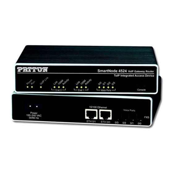
Model 4520 & 4110 Series Getting Started Guide 1 • General information Figure 4. SmartNode 4520 Series front panels LED descriptions This section describes the SmartNode 4520 Series front panel LEDs (see figure Note If an error occurs, all LEDs will flash once per second. •... -
Page 20: Smartnode 4110 Series Router
Model 4520 & 4110 Series Getting Started Guide SmartNode 4110 Series router The SmartNode 4110 Series is a compact VoIP gateway, which supports two to eight voice channels. The fol- lowing models (each equipped with one 10/100Base-T Ethernet port) are available (see figure... -
Page 21: Ports Descriptions
Model 4520 & 4110 Series Getting Started Guide 1 • General information Ports descriptions The SmartNode 4110 Series rear panel ports are described in table Table 4. Rear panel ports Port Location Description 10/100 Ethernet Rear panel RJ-45 connector (see on page 20) that connects the router to an figure 5... -
Page 22: Led Descriptions
Model 4520 & 4110 Series Getting Started Guide Figure 7. SmartNode 4110 Series front panels LED descriptions This section describes the SmartNode 4110 Series front panel LEDs. Note If an error occurs, all LEDs will flash once per second. •... - Page 23 Model 4520 & 4110 Series Getting Started Guide 1 • General information • VoIP Link—When lit, indicates the gateway is registered on a gatekeeper, media gateway controller, associ- ated to a remote unit, or has an active VoIP connection. Off indicates the unit is not configured or regis- tered and has no active VoIP connection.
- Page 24 1 • General information Model 4520 & 4110 Series Getting Started Guide SmartNode Series VoIP routers overview...
-
Page 25: Applications Overview
Chapter 2 Applications Overview Chapter contents Introduction ................................26 Applications for SmartNode 4110 Series .......................26 H.323 terminal media gateway ........................26 Application—Private line automatic ringdown (PLAR) ..................27 Application—Enterprise campus BRI to FXS telephony extension ..............27 Application—PBX toll bypass gateway ......................28 Applications for SmartNode 4520 Series .......................29... -
Page 26: Introduction
VoIP networks. This chapter describes typical applica- tions for which the routers are uniquely suited. Applications for SmartNode 4110 Series The SmartNode 4110 Series, equipped with a single Ethernet port, provide gateway and over-IP line extension services. H.323 terminal media gateway... -
Page 27: Application-Private Line Automatic Ringdown (Plar)
Application—Enterprise campus BRI to FXS telephony extension In combination with the Patton SmartNode 1000 and 2000 Series models the FXS gateways provide ISDN BRI to FXS extensions over IP (see figure 10). Figure 10. BRI to FXS extension Applications for SmartNode 4110 Series... -
Page 28: Application-Pbx Toll Bypass Gateway
PBX systems. A call routed to the FXS gateway can be relayed on a port-to-port basis to the remote gateway or on a dialled number basis. Note With the use of FXS ports extension dialing on the secondary side must be done through two stage dialling (DTMF relay). Figure 11. Toll bypass Applications for SmartNode 4110 Series... -
Page 29: Applications For Smartnode 4520 Series
Model 4520 & 4110 Series Getting Started Guide 2 • Applications Overview Applications for SmartNode 4520 Series These models have dual 10/100Base-T Ethernet ports. The second Ethernet port provides Ethernet and IP layer QoS services. Voice prioritization and rate limitation to avoid network congestion and the respective voice quality degradation. -
Page 30: Applications In Combination With Fxo Models
2 • Applications Overview Model 4520 & 4110 Series Getting Started Guide Applications in combination with FXO models The FXO models will enable the provisioning of POTS (FXS to FXO) extension over any existing Ethernet/IP network. The FXS ports will allow a standard POTS handset to seamlessly connect to a remote PSTN line or PBX extension port over a packet network. -
Page 31: Installation
Chapter 3 Installation Chapter contents Planning the installation ............................32 Installation checklist ............................33 Site log ................................34 Network information ............................34 Network Diagram .............................34 IP related information .............................34 Software tools ..............................34 Power source ..............................34 Location and mounting requirements ......................35 Installing the gateway router..........................35 Mounting the gateway router ..........................35 Connecting cables... -
Page 32: Planning The Installation
3 • Installation Model 4520 & 4110 Series Getting Started Guide Planning the installation Before you start the actual installation, it is strongly recommended that you gather all the information needed to install and setup the device. See table 5 for an example of what pre-installment checks you might need to carry out. -
Page 33: Installation Checklist
Model 4520 & 4110 Series Getting Started Guide 3 • Installation Installation checklist The installation checklist (see table 5) lists the tasks for installing a SmartNode 4520 or 4110 Series router. Make a copy of this checklist and mark the entries as you complete each task. For each SmartNode 4520 or 4110 Series router, include a copy of the completed checklist in your site log. -
Page 34: Site Log
3 • Installation Model 4520 & 4110 Series Getting Started Guide Site log Patton recommends that you maintain a site log to record all actions relevant to the system, if you do not already keep such a log. Site log entries should include information such as listed in table Table 6. -
Page 35: Location And Mounting Requirements
Model 4520 & 4110 Series Getting Started Guide 3 • Installation Location and mounting requirements The SmartNode router is intended to be placed on a desktop or similar sturdy, flat surface that offers easy access to the cables. Allow sufficient space at the rear of the chassis for cable connections. Additionally, you should consider the need to access the unit for future upgrades and maintenance. -
Page 36: Installing An Interface Cable On The Router's Fxs Interface Port
3 • Installation Model 4520 & 4110 Series Getting Started Guide Installing an interface cable on the router’s FXS interface port The gateway comes with at least two FXS voice ports (see figure 13) located on the back of the router. The FXS interfaces are connected to analog devices via cables (see figure 14) terminated with RJ-11 connectors (see... - Page 37 Model 4520 & 4110 Series Getting Started Guide 3 • Installation Figure 15. RJ-11 pinout diagram Table 7. RJ-11 socket Signal Ring (-) Tip (+) Figure 16. Router front panel LEDs and Console port locations (SmartNode 4524 shown) Installing the gateway router...
-
Page 38: Installing The Ethernet Cable
(see table 8 for port pin-out listing) via a cable terminated with RJ-45 plugs. A cross-over cable is only required when connecting SmartNode 4110 Series devices to a host (see figure 18 on page 39). Table 8. Ethernet 10/100Base-T (RJ-45) port pin-outs... - Page 39 Model 4520 & 4110 Series Getting Started Guide 3 • Installation Figure 18. Connecting to a host (cross-over cable required for SmartNode 4110 Series only) Installing the gateway router...
-
Page 40: Installing The Power Cord
3 • Installation Model 4520 & 4110 Series Getting Started Guide Installing the power cord The router comes with an internal or external power supply. This section describes installing the power cord into the router. Do the following: Note Do not connect the other end of the power cord to the power outlet at this time. 1. -
Page 41: Getting Started With The Smartnode
Chapter 4 Getting started with the SmartNode Chapter contents Introduction ................................42 1. Configure IP address ............................43 Power connection and default configuration ....................43 Connect with the serial interface ........................43 Login ................................44 Changing the IP address ..........................44 2. Connect the SmartNode to the network ......................45 3. -
Page 42: Introduction
4 • Getting started with the SmartNode Model 4520 & 4110 Series Getting Started Guide Introduction This chapter leads you through the basic steps to set up a new SmartNode and to download a configuration. Patton SmartNodes can be used for a wide variety of IP-based network applications. To support and ease the configuration of the SmartNodes configuration, templates for the most important applications are available on the Patton server at www.patton.com/voip. -
Page 43: Configure Ip Address
Model 4520 & 4110 Series Getting Started Guide 4 • Getting started with the SmartNode 1. Configure IP address Power connection and default configuration First the SmartNode must be connected to the mains power supply with the power cable. Wait until the 'Run' LED stops blinking and lights constantly. -
Page 44: Login
4 • Getting started with the SmartNode Model 4520 & 4110 Series Getting Started Guide Login Accessing your SmartNode via the local console port (or via a Telnet session) causes the login screen to display. Type the factory default login: administrator and leave the password empty. Press the Enter key after the pass- word prompt. -
Page 45: Connect The Smartnode To The Network
Model 4520 & 4110 Series Getting Started Guide 4 • Getting started with the SmartNode 2. Connect the SmartNode to the network Depending whether you connect the SmartNode to a host directly or via a hub or switch either straight- through wired or cross-over cables must be used (see figure 22). -
Page 46: Additional Information
4 • Getting started with the SmartNode Model 4520 & 4110 Series Getting Started Guide Press ’yes’ to restart, ’no’ to cancel : yes The system is going down Additional information For detailed information about configuring and operating guidance, set up procedures, and troubleshooting, refer to the Software Configuration Guide on the enclosed CD-ROM. -
Page 47: Monitoring Status
Chapter 5 Monitoring Status Chapter contents Status LEDs................................48... -
Page 48: Status Leds
This chapter describes SmartNode gateway router front panel LEDs. Figure 23 shows SmartNode 4520 Series LEDs, figure 24 on page 49 shows SmartNode 4110 Series LEDs. LED definitions are listed in table 10 page 50. Figure 23. SmartNode 4520 Series front panels Status LEDs... - Page 49 Model 4520 & 4110 Series Getting Started Guide 5 • Monitoring Status Figure 24. SmartNode 4110 Series front panels Status LEDs...
- Page 50 5 • Monitoring Status Model 4520 & 4110 Series Getting Started Guide Table 10. SmartNode LED Indications Description Note If an error occurs, all LEDs will flash once per second. Power When lit, indicates power is applied. Off indicates no power applied. When lit, indicates normal operation.
-
Page 51: Contacting Patton For Assistance
Chapter 6 Contacting Patton for assistance Chapter contents Introduction ................................52 Contact information..............................52 Warranty Service and Returned Merchandise Authorizations (RMAs)..............52 Warranty coverage ............................52 Out-of-warranty service ..........................52 Returns for credit ............................52 Return for credit policy ..........................53 RMA numbers ..............................53 Shipping instructions ..........................53... -
Page 52: Introduction
6 • Contacting Patton for assistance Model 4520 & 4110 Series Getting Started Guide Introduction This chapter contains the following information: • “Contact information”—describes how to contact Patton technical support for assistance. • “Warranty Service and Returned Merchandise Authorizations (RMAs)”—contains information about the RAS warranty and obtaining a return merchandise authorization (RMA). -
Page 53: Return For Credit Policy
Model 4520 & 4110 Series Getting Started Guide 6 • Contacting Patton for assistance Return for credit policy • Less than 30 days: No Charge. Your credit will be issued upon receipt and inspection of the equipment. • 30 to 60 days: We will add a 20% restocking charge (crediting your account with 80% of the purchase price). •... - Page 54 6 • Contacting Patton for assistance Model 4520 & 4110 Series Getting Started Guide Warranty Service and Returned Merchandise Authorizations (RMAs)
- Page 55 Appendix A Specifications Chapter contents DSP..................................56 Voice connectivity ..............................56 Connectivity................................56 Voice processing (signalling dependent).........................56 Fax and modem support............................56 Voice Signalling..............................57 Voice Routing—Session Router ..........................57 IP services ................................57 Management .................................58 Operating Environment ............................58 Operating temperature ............................58 Operating humidity ............................58 System ...................................58 Compliance ................................58 Dimensions...
-
Page 56: A Specifications
A • Specifications Model 4520 & 4110 Series Getting Started Guide One or two 4-channel DSPs Voice connectivity 2-wire Loopstart, RJ-11/12 Short haul loop 1.1 km @3REN EuroPOTS (ETSI EG201 188) Programmable AC impedance, feeding, and ring voltage; On-Hook Voltage 29VDC Caller-ID Type-1/2 FSK and ITU V.23/Bell 202 generation Connectivity 2 10/100 Full Duplex/Autosensing Ethernet RJ-45... -
Page 57: Voice Signalling
Model 4520 & 4110 Series Getting Started Guide A • Specifications Voice Signalling H.323v4 • RAS, H.225, H.245 • Fast-connect, early H.245 • Gatekeeper autodiscovery • Alias registration • Overlap sending • Empty capability set (call transfer, hold) • H.323v1 call transfer, hold ISDN over IP (ISoIP) •... -
Page 58: Management
A • Specifications Model 4520 & 4110 Series Getting Started Guide IPSEC AH & ESP Modes Manual Key; IKE optional AES/DES/3DES Encryption Management Industry standard CLI with local console (CRJ-45, RS-232) and remote Telnet access TFTP configuration & firmware loading SNMP v1 agent (MIB II and private MIB) Built-in diagnostic tools (trace, debug) Java™... -
Page 59: Weight
Model 4520 & 4110 Series Getting Started Guide A • Specifications Weight table Table 11. SmartNode weight and maximum power specifications SmartNode model Weight Maximum power dissipation 4112/4522 30.5 oz (500 g) 4114/4524 30.5 oz (500 g) 4116/4526 24.4 oz (400 g 4118/4528 24.4 oz (400 g a. - Page 60 A • Specifications Model 4520 & 4110 Series Getting Started Guide Power supply...
- Page 61 Appendix B Cabling Chapter contents Introduction ................................62 Serial console .................................62 Ethernet 10Base-T and 100Base-T ........................63 Analog FXS ................................64...
-
Page 62: B Cabling
B • Cabling Model 4520 & 4110 Series Getting Started Guide Introduction This section provides information on the cables used to connect the SmartNode and the interface cards to the existing network infrastructure and to third party products. Serial console The SmartNode can be connected to a serial terminal over its serial console port, as depicted in figure Figure 25. -
Page 63: Ethernet 10Base-T And 100Base-T
Model 4520 & 4110 Series Getting Started Guide B • Cabling Ethernet 10Base-T and 100Base-T Ethernet devices (10Base-T/100Base-T) are connected to the SmartNode over a cable with RJ-45 plugs. Use a cross-over cable to a host, or a straight cable to a hub. See figure 26 (host) and figure 27... -
Page 64: Analog Fxs
B • Cabling Model 4520 & 4110 Series Getting Started Guide Figure 27. Ethernet straight-through Analog FXS The router come with at least two FXS voice ports located on the back of the router. The FXS interfaces are connected to analog devices via cables terminated with RJ-11 connectors. Figure 28. - Page 65 Appendix C Port pin-outs Chapter contents Introduction ................................66 Console port................................66 Ethernet 10Base-T and 100Base-T port.........................66 port................................66...
-
Page 66: C Port Pin-Outs
C • Port pin-outs Model 4520 & 4110 Series Getting Started Guide Introduction This section provides pin-out information for the ports of the SmartNode. Console port Figure 29. EIA-561 (RJ-45 8-pin) port Note Pins not listed are not used. Ethernet 10Base-T and 100Base-T port Table 12.
Need help?
Do you have a question about the SMARTNODE 4110 Series and is the answer not in the manual?
Questions and answers