Table of Contents
Advertisement
Advertisement
Table of Contents

Subscribe to Our Youtube Channel
Related Manuals for Harmonic Electra9200


Summary of Contents for Harmonic Electra9200
- Page 1 Electra 9200 Multichannel Encoder Installation Guide Rev O...
- Page 2 Harmonic assumes no responsibility or liability arising from the use of the products described herein, except as expressly agreed to in writing by Harmonic. The use and purchase of this product do not convey a license under any patent rights, copyrights, trademark rights, or any intellectual property rights of Harmonic.
- Page 3 Commercial Computer Software and Commercial Computer Software Documentation are being licensed to U.S. Government as end users (a) only as Commercial Items and (b) with only those rights as are granted to all other end users pursuant to the terms and conditions herein. Harmonic, 4300 North First Street, San Jose, CA 951 34 U.S.A.
- Page 4 CAUTION: The Caution symbol calls your attention to information that, if ignored, can adversely affect the performance of your Harmonic product, or that can make a procedure needlessly difficult. LASER DANGER: The Laser symbol and the Danger alert call your attention to information about the lasers in this product that, if ignored, can cause physical harm to you.
-
Page 5: Table Of Contents
Licensing Information........... 25 © 2015 Harmonic Inc. - Page 6 AHC-RAC Audio Encoding Features ........56 © 2015 Harmonic Inc.
- Page 7 Appendix B: Audio Specifications............80 Appendix C: Encoder Back Panel Slot Specifications ......83 Appendix D: Contacting the Technical Assistance Center ....85 Appendix E: Safety and Regulatory Compliance Information ..87 © 2015 Harmonic Inc. Electra 9200, Rev O...
-
Page 8: Introduction
Manual Organization Introduction This manual describes the Harmonic Electra® 9200 Universal SD/HD MPEG-2 and AVC Encoder series. It describes the encoder features, the various optional components that can be integrated into the encoder, and provides instructions for basic installation and setup. - Page 9 Introduction Manual Organization Appendix C, Encoder Back Panel Slot Specifications, describes the back panel slots for the encoder. © 2015 Harmonic Inc. All rights reserved. Electra 9200, Rev O...
-
Page 10: Chapter 1 Electra 9200 Overview
The encoder operates within an ASI or IP environment, allowing flexible network architectures. In an IP environment, encoders and multiplexers do not need to be in the same physical location. © 2015 Harmonic Inc. All rights reserved. Electra 9200, Rev O... -
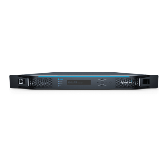
Page 11: Front And Back Panels
Status indicator Latch Front panel latch Right key Menu right ESC key Menu escape ENTER key Menu Select Down key Menu down Left key Menu left Up key Menu up © 2015 Harmonic Inc. All rights reserved. Electra 9200, Rev O... -
Page 12: Optional Modules
Audio module that can accept MPEG-2 TS and SDI inputs Module AHC-RAC (AHC-RAC Audio module that can accept AES3/S/PDIF inputs Module) AHC-561 (AHC-561 Audio module that can accept AES3/S/PDIF inputs Module) © 2015 Harmonic Inc. All rights reserved. Electra 9200, Rev O... -
Page 13: Features Overview
Up to two outputs plus PiP per video input High-quality integrated decoding with FLEX™ option Statmux over IP in LAN and WAN environments with DiviTrackIP™ Integrated statmux with DiviTrackMX™ © 2015 Harmonic Inc. All rights reserved. Electra 9200, Rev O... - Page 14 (Up to 16 stereo pairs using IOM-RAC2) Built-in, broadcast-quality up/down conversion Using optional audio cards: pass-through of precompressed audio, encode from PCM audio, multichannel to stereo down mix, and audio leveling. © 2015 Harmonic Inc. All rights reserved. Electra 9200, Rev O...
-
Page 15: Chapter 2: Installing The Encoder
Preparing the Encoder You need a Phillips-head screwdriver to mount the encoder in a standard 19-inch rack. Harmonic ships the necessary rack-mount screws and rack rails with the optional rack- mounting kit. The encoder comes in a specially designed shipping container that ensures the integrity of your encoder hardware during shipping and handling. -
Page 16: Rack Guidelines
Bauteil unten im Gestell anzubringen ist. Wird das Gestell mit Stabilisierungszubehör geliefert, sind zuerst die Stabilisatoren zu installieren, bevor sie die Einheit im Gestell anbringen oder sie warten. © 2015 Harmonic Inc. All rights reserved. Electra 9200, Rev O... -
Page 17: Airflow
3. Using the #10 screws provided with the encoder, screw the mounts into the speed nuts from the inside of the rack using the rack-mount holes that line up with the holes on the rack posts. Figure 2–2 illustrates attaching the rails. © 2015 Harmonic Inc. All rights reserved. Electra 9200, Rev O... -
Page 18: Mounting The Encoder
CAUTION: Rack mount the encoder using the screws that came with your Harmonic rail kit. If you did not purchase a Harmonic rail kit, use a rack-mount screw with a head no larger than 0.4 inches in diameter and 0.14 inches in height to avoid damaging the front panel of the encoder. (Some encoders may come with a peel-away sticker that advises on the correct screw size.) Using only the bottom two... -
Page 19: Cabling The Encoder
2. Continue connecting the additional video sources to the remaining video ports. Connecting the IP Output Cables For RJ-45 pinouts, see RJ-45 Ethernet Port Pinouts. Ports 3 and 4 are GbE output ports. © 2015 Harmonic Inc. All rights reserved. Electra 9200, Rev O... -
Page 20: Connecting The Ip Input Cables
IP address. Harmonic recommends that shielded and grounded Ethernet cables be used on all Ethernet ports. Failure to properly configure the Ethernet switch could result in a mismatch between the IP output and the switch. -
Page 21: Connecting The Fault Relay/General Purpose Interface (Gpi) Ports
When configured in the DPI properties page of NMX, an SCTE35 message is sent out when that pin is set to low. (RN-05) Figure 2–4: Fault Relay/GPI Ports For Fault Relay and GPI pinouts, see Fault Relay/General Purpose Interface (GPI) Ports. © 2015 Harmonic Inc. All rights reserved. Electra 9200, Rev O... -
Page 22: Connecting The Serial Data Port
Ensure that a fuse or circuit breaker no larger than 120 VAC, 20 A U.S. (240 VAC, 20 A international) is used on the phase conductors (all current-carrying conductors). © 2015 Harmonic Inc. All rights reserved. Electra 9200, Rev O... -
Page 23: Connecting The Dc Power Supply
DC power supply for the Electra 9200, which is located on the back panel. 40V - 60V 15A Max. (RN-06) Figure 2–5: DC Power Supply for Electra 9200 © 2015 Harmonic Inc. All rights reserved. Electra 9200, Rev O... - Page 24 NOTE: Overcurrent protection devices must meet applicable national and local electrical safety codes and be approved for the intended application. Wiring Requirements The encoder is connected to the DC power source using three wires: –Vin © 2015 Harmonic Inc. All rights reserved. Electra 9200, Rev O...
- Page 25 Chapter 2 Installing the Encoder Connecting the Power +Vin Although Harmonic provides the power input connector with the Electra-9200D, you must supply the wires. The wires must comply with the specifications shown in Table 2–2. Table 2–2: DC Power Wire Requirements...
-
Page 26: The Boot Sequence
Messages on the local control panel indicate progress during boot-up. During a successful boot, many events occur so quickly you cannot see the messages. The following sections describe the messages that you can see during boot attempts. © 2015 Harmonic Inc. All rights reserved. Electra 9200, Rev O... -
Page 27: Messages When Resetting The Encoder
VFD line 2 = Multichannel Encoder Front Panel LEDs The four LEDs on the front panel indicate the operational state of the encoder. Table 2–3 describes the front panel LEDs. © 2015 Harmonic Inc. All rights reserved. Electra 9200, Rev O... -
Page 28: Back Panel Leds
NMX. Use the Locator LED to help you identify a specific chassis in a rack. Fault The Fault LED lights when the application software detects an alarm. The front panel and back panel Fault LEDs light at the same time. © 2015 Harmonic Inc. All rights reserved. Electra 9200, Rev O... -
Page 29: Video Lock Leds
When illuminated and steady, the Video Lock LED indicates that the video signal is locked. When off, the Video Lock LED indicates that the encoder has lost video sync. © 2015 Harmonic Inc. All rights reserved. Electra 9200, Rev O... -
Page 30: Chapter 3 Operating The Encoder
MAC address in the front panel display. While you can perform all platform and configuration tasks from NMX, you will use Harmonic NodeLock License Manager to manage any feature license additions/deletions. For information about feature licensing on the Electra 9200, see Licensing Information. -
Page 31: Front Panel Display
Value to be Edited Figure 3–2: Setting a Value in the Front Panel Display A blinking cursor shows the current value. A steady cursor shows the value being edited. © 2015 Harmonic Inc. All rights reserved. Electra 9200, Rev O... -
Page 32: Licensing Information
Licensing Information Licensing is required for some encoding features, and you cannot enable those features without the appropriate licensing. You can add licenses to your system using the Harmonic NLM 4.0 (NodeLock License Manager). Most licenses are permanent—once enabled the feature will continue to function without raising license-related alarms. -
Page 33: Chapter 4: Electra 9200 Specifications
(2.0) pairs or 1 5.1 multichannel AC-3 metadata input through VANC AAC/HE AAC compression; up to three stereo (2.0) pairs or one 5.1 multichannel with MPEG-2 or MPEG-4 encapsulation Audio description for audio coding © 2015 Harmonic Inc. All rights reserved. Electra 9200, Rev O... - Page 34 IRIS™ Support Quality of Service (QoS) Data reporting for video and audio quality. This data can by used for performance analysis by Harmonic’s IRIS system or by a third-party system. The surround mix on the three AES3 pairs uses channel mapping per SMPTE 320M (L/R, C/Lfe, Ls/Rs).
-
Page 35: Optional Features
ASI In 1 per chassis NOTE: The AHC-561 audio card is being deprecated on the Electra 9200/9200D. IOM-RAC2 and AHC- RAC are the recommded audio cards for that encoder. © 2015 Harmonic Inc. All rights reserved. Electra 9200, Rev O... -
Page 36: Video Features
1080i29.97 Conversion between 576i25, 720p50, and 1080i25 Conversion between 720p59.94 and 1080i29.97 or 1080i29.97 and 720p59.94 Digital Program Insertion SCTE 35 insertion via SCTE 104 or VANC DPI triggers © 2015 Harmonic Inc. All rights reserved. Electra 9200, Rev O... -
Page 37: Vitc Support
MPEG-1L2 56 to 384 kbps AC-3: 56 to 640 kbps AAC: 32 to 640 kbps / HE AAC: 32 to 1 28 kbps Audio sampling 32 kHz frequency 44.1 kHz 48kHz © 2015 Harmonic Inc. All rights reserved. Electra 9200, Rev O... -
Page 38: Audio Encoder Features
, 51 2 , 640 Up to 5.1 channels 32 kHz 256, 320, 384, 448 (3/2+LFE professional 32- 44.1 kHz 51 2 , 576 , 640 bit mode) 48 kHz © 2015 Harmonic Inc. All rights reserved. Electra 9200, Rev O... - Page 39 “Low Overhead Audio Stream,” and furnishes an outer wrapper for LATM's inner wrapper of the raw audio Elementary Stream syntax. MPEG-4 AAC and HE AAC bitstreams are encapsulated as LATM/LOAS and assigned a stream type value of 0x1 1. © 2015 Harmonic Inc. All rights reserved. Electra 9200, Rev O...
-
Page 40: Ip Input And Output Support And Specifications
MPEG-2 TS over UDP/IP 1 to 7 TS/ IP MPEG format 188 bytes per TS packet MPEG-2 TS MPTS and SPTS Maximum Bit-Rate 180 Mbps Addressing Unicast and multicast Management IGMP, ARP, and ICMP © 2015 Harmonic Inc. All rights reserved. Electra 9200, Rev O... -
Page 41: Divitrack Features
64 across 3 pools Max ASI output rate of services per ProStream 1000 ProStream 1000 MUX is 160Mbps Round-trip Delay 300msec Priorities Very Low For SD MPEG-2 only Medium High Very High © 2015 Harmonic Inc. All rights reserved. Electra 9200, Rev O... -
Page 42: Divitrackmx Support
SCTE 35 messages, which are placed in the outgoing MPEG Transport Stream. HHP Support Harmonic Heartbeat Protocol (HHP) is a proprietary Harmonic protocol used to prevent duplicate IP output after a redundancy switch and to initiate a redundancy switch in some 1×1 hot backup scenarios. - Page 43 HHP message from the primary device during a specified interval, it initiates a redundancy switch and assumes operation as the primary device. NOTE: HHP and IGMP version 3 are not compatible at this time. © 2015 Harmonic Inc. All rights reserved. Electra 9200, Rev O...
-
Page 44: Chapter 5: Maintenance And Troubleshooting
Your encoder comes from the factory with the latest released software version installed. Harmonic periodically releases software updates. You can download new software to the encoder using NMX. See the NMX online help for instructions for how to download and begin running new encoder software. -
Page 45: Removing And Replacing The Bezel
3. Ease the the bezel away from the fan tray. The bezel is secured to the fan tray by a clip, as shown in step 3, Figure 5–1. 4. Ease the left side of the bezel away from the unit, as shown in step 4, Figure 5–1. © 2015 Harmonic Inc. All rights reserved. Electra 9200, Rev O... -
Page 46: Air Filter
Inspect and clean the filter with a frequency that is appropriate to the environment in which the encoder operates. Harmonic recommends inspecting and cleaning the filter every six weeks to ensure proper airflow through the chassis. -
Page 47: Removing And Replacing The Air Filter
NOTE: When the filter is new, its color is medium charcoal. As dust and dirt collect in the porous filter material, the color of the filter gradually changes to brown, then to an ash color. © 2015 Harmonic Inc. All rights reserved. Electra 9200, Rev O... -
Page 48: Ac Power Supply Fuse
1. Unplug the power cord from the chassis. DANGER: You must disconnect the power cord before removing the fuse. 2. Pull down the fuse cover. 3. Remove the old fuse. © 2015 Harmonic Inc. All rights reserved. Electra 9200, Rev O... -
Page 49: Fan Tray
4. Install the new fuse. DANGER: Always replace the fuse with a fuse of the same rating and type. Using a different fuse voids the Harmonic warranty and could result in fire or other electrical damage. 5. Replace the fuse cover. -
Page 50: Power Supply
2. Remove the bezel from the chassis, as described in Removing and Replacing the Bezel. 3. Remove the fan tray unit from the chassis, as described in Removing and Replacing the Fan Tray. © 2015 Harmonic Inc. All rights reserved. Electra 9200, Rev O... - Page 51 5. Grasp the metal handle on the front of the power supply unit and pull firmly to disengage the power supply from the connector, as shown in Figure 5–8. 6. Slide the power supply away from the unit. © 2015 Harmonic Inc. All rights reserved. Electra 9200, Rev O...
-
Page 52: Input/Output Modules
Optional Features additional information on each of these modules. NOTE: Before making changes to the FLEX-1 Module, make sure the service configuration is cleared before powering down the system. © 2015 Harmonic Inc. All rights reserved. Electra 9200, Rev O... -
Page 53: Removing And Replacing An Input/Output(I/O) Module
1, Figure 5–10. (RN-16) Figure 5–10: Removing an I/O module 2. Pull firmly on the module to remove it from the chassis, as shown in step 2, Figure 5–10. © 2015 Harmonic Inc. All rights reserved. Electra 9200, Rev O... -
Page 54: Audio Video Processing Modules (Avpm)
2. Remove the bezel from the chassis, as described in Removing and Replacing the Bezel. 3. Remove the fan tray assembly from the chassis, as described in Removing and Replacing the Tray. © 2015 Harmonic Inc. All rights reserved. Electra 9200, Rev O... - Page 55 Figure 5–12. (RN-18) Figure 5–12: Removing the Card Retaining Device 5. If a mini-SDI connector is present, disconnect the connector identified in step 5 in Figure 5–13. © 2015 Harmonic Inc. All rights reserved. Electra 9200, Rev O...
- Page 56 Chapter 5 Maintenance and Troubleshooting Audio Video Processing Modules (AVPM) (RN-19) Figure 5–13: Removing an AVPM 6. Grab the card handle and slide the card from the chassis, as shown in Figure 5–13. © 2015 Harmonic Inc. All rights reserved. Electra 9200, Rev O...
- Page 57 4. Reattach the card retainer. 5. Reinsert the fan tray as described in Removing and Replacing the Fan Tray. 6. Reinstall the bezel as described in Removing and Replacing the Bezel. © 2015 Harmonic Inc. All rights reserved. Electra 9200, Rev O...
-
Page 58: Chapter 6: Audio Modules
AC-3 2.0 or 5.1 pass-through. E-AC-3 2.0 or 5.1 pass-through. Dolby E pass-through. Up to five AHC-RAC modules supported per 9200 chassis. See AHC-RAC Module more information. © 2015 Harmonic Inc. All rights reserved. Electra 9200, Rev O... -
Page 59: Iom-Rac2 Module
No more than one IOM-RAC2 can be installed in a chassis. All audio services will be routed through it. When an IOM-RAC2 is installed in a chassis, all provisioned audio streams will be routed and processed by the IOM-RAC2. © 2015 Harmonic Inc. All rights reserved. Electra 9200, Rev O... -
Page 60: Iom-Rac2 Audio Encoding Features
32 kHz Stereo channel (2.0) 44.1 kHz Joint stereo channel 48 kHz MPEG-1 Layer II Single channel (1.0) 32 kHz compression 44.1 kHz SPPC (separate PID 48 kHz per channel) © 2015 Harmonic Inc. All rights reserved. Electra 9200, Rev O... - Page 61 32 kHz compression 44.1 kHz 48 kHz Dual channel (1+1) 32 kHz Stereo channel (2.0) 44.1 kHz Joint stereo channel 48 kHz Multi-channel (5.1) 32 kHz 44.1 kHz 48 kHz © 2015 Harmonic Inc. All rights reserved. Electra 9200, Rev O...
-
Page 62: Ahc-Rac Module
Figure 6–1: AHC-RAC Digital Audio Input Ports Connecting the AHC-RAC Audio Input Cables Connect a coaxial cable with BNC connectors from the digital audio port to the audio source: © 2015 Harmonic Inc. All rights reserved. Electra 9200, Rev O... -
Page 63: Ahc-Rac Audio Encoding Features
For discrete AES3 inputs, sampling frequencies of 48 kHz, 44.1 kHz, and 32 kHz are supported. Embedded in digital video is supported only for 48 kHz sampling, which must be synchronous to the video. © 2015 Harmonic Inc. All rights reserved. Electra 9200, Rev O... - Page 64 , 192 Joint stereo channel 48 kHz , 256 , 320 , 384 Multi-channel (5.1) 32 kHz 96, 1 1 2, 1 28, 160, 192 44.1 kHz 48 kHz © 2015 Harmonic Inc. All rights reserved. Electra 9200, Rev O...
- Page 65 Elementary Stream syntax. MPEG-4 AAC and HE AAC bitstreams are encapsulated as LATM/LOAS and assigned a stream type value of 0x1 1.Encapsulation mode is controlled by selecting ”MPEG-2” or ”MPEG-4” as required. © 2015 Harmonic Inc. All rights reserved. Electra 9200, Rev O...
-
Page 66: Ahc-Rac Metadata Connection
RJ45 connector that can be used to supply Dolby serial audio metadata (this is not an Ethernet connector). Up to 4 AHC-561 cards can be installed in a chassis. Figure 6–3: AHC-561 Digital Audio Input Ports © 2015 Harmonic Inc. All rights reserved. Electra 9200, Rev O... -
Page 67: Connecting The Ahc-561 Audio Input Cables
The metadata can be received via a serial stream through the AHC-561's RJ-45 connector. Section AHC-RAC Metadata Connection describes the serial connection for this port. © 2015 Harmonic Inc. All rights reserved. Electra 9200, Rev O... -
Page 68: Chapter 7: Flex Decoding Module
Installing the FLEX-1 Decoding Module Introduction The Harmonic FLEX-1 decoder module performs video and audio decoding of compressed input and output decoded elementary streams directly to the encoder audio/video processing cards. A single FLEX-1 Module is able to decode up to two incoming channels, and an appropriately configured encoder can support up to two FLEX-1 Modules delivering up to four channels in a single rack-unit (1-RU). - Page 69 Rev OCabling the FLEX-1 Module is very straight forward. All ports are clearly marked. The examples include tables that list the ports and required connectors. NOTE: For the monitor ports there is a DIN to BNC pigtail connector that can be ordered. Harmonic Part number: FLEX-MON, 229-0054067.
-
Page 70: Two Channel Flex System
Monitor 1 75 cable. The slot 5 Monitor 1 output port can be DIN 1.0/2.3 Slot 5 used for monitoring and troubleshooting purposes. © 2015 Harmonic Inc. All rights reserved. Electra 9200, Rev O... -
Page 71: Configuring The Flex-1 Module In Nmx
Auto Format Detection Automatically switch between 1080i and 720p formats when the HD-SDI input changes formats Switch performed within 30 seconds Not supported with downconversion Requires an optional firmware license. © 2015 Harmonic Inc. All rights reserved. Electra 9200, Rev O... -
Page 72: Audio Specifications
Level Magic™ Dynamic Audio Leveling. Table 7–6: FLEX Audio Decode Specifications Feature Support Audio Decoding Format MPEG1-L2 AC-3 Audio Decoding Mode Mono, stereo, or multi-channel (5.1) and multichannel (5.1) down-mix to stereo © 2015 Harmonic Inc. All rights reserved. Electra 9200, Rev O... -
Page 73: Audio Decoding Resource Considerations
Up to two multichannel audio decode and two stereo audio decode streams on the first FLEX decoding channel (with no audio on the second channel) Up to eight mono/stereo decode streams on the first FLEX decoding port (with no audio on second channel) © 2015 Harmonic Inc. All rights reserved. Electra 9200, Rev O... - Page 74 Silence on the decoding right channel. mode) Stereo Stereo Audio on both channels Stereo Multichannel Audio on both 3 x Stereo left and right channels. Silence on all others. © 2015 Harmonic Inc. All rights reserved. Electra 9200, Rev O...
-
Page 75: Level Magic™ Dynamic Audio Leveling
Dynamic leveling uses the same technology found in Jünger Audio’s Level Magic™ hardware- based processors. Level Magic is a trademark of Jünger Audio Studiotechnik GmbH. The dynamic leveling option requires a firmware license. © 2015 Harmonic Inc. All rights reserved. Electra 9200, Rev O... -
Page 76: Ancillary Data Specifications
Table 7–11: Input Specifications Feature Support Transport stream Inputs MPEG-2 TS IP input Connecting the IP Input Cables ASI Input Table 8–1 on page 71 RF Input on page 73 Table 9–1 © 2015 Harmonic Inc. All rights reserved. Electra 9200, Rev O... -
Page 77: Output Specifications
Keep the module inside the antistatic bag until you are ready to install the module in a chassis. Installing a Module Refer to for instructions on how to install a Removing and Replacing an Input/Output(I/O) Module module. © 2015 Harmonic Inc. All rights reserved. Electra 9200, Rev O... -
Page 78: Chapter 8: Asi Module
Maximum length of ASI cable is approximately 900 feet (300m); there is no minimum specified. MPEG format 188/204 bytes per TS packet Max output bit rate Up to 1 55 Mbps per port © 2015 Harmonic Inc. All rights reserved. Electra 9200, Rev O... -
Page 79: Connecting The Asi Output Cables
NOTE: The maximum length of ASI cable is approximately 900 feet; there is no minimum specified. To connect the ASI input cables: Connect an ASI cable with 75-ohm BNC coaxial connector from ASI port three or port four to an appropriate input device. © 2015 Harmonic Inc. All rights reserved. Electra 9200, Rev O... -
Page 80: Chapter 9: Atsc Rf Input Module
Environmental and Physical Compliant with ROHS Directive 2002/95/EC. Refer to the encoder environmental specifications for additional information. Figure 9–1 displays the module (rear panel). Figure 9–1: RF Input Module © 2015 Harmonic Inc. All rights reserved. Electra 9200, Rev O... -
Page 81: Rf Module Led Lights
Table 9–2: LED Status Lights Display Status Port disabled Blinking Yellow Loss of sync Packet error rate (PER) threshold exceeded Steady yellow SNR below threshold Green Port Enabled, no alarms © 2015 Harmonic Inc. All rights reserved. Electra 9200, Rev O... -
Page 82: Appendix A: Encoder Physical Specifications
–48 VDC Input voltage range –40 to –60 VDC Temperature Operating +32º to +1 22º F 0º to +50º C° Storage –20 to +80 °C (–4 to +1 76 °F) © 2015 Harmonic Inc. All rights reserved. Electra 9200, Rev O... - Page 83 Up to three stereo pairs or one multi channel for the on- board audio Format Embedded in SDI AES3 signal format per AES3-2003 and ITU-R BS.647-2 S/PDIF signal format per IEC 60958 © 2015 Harmonic Inc. All rights reserved. Electra 9200, Rev O...
- Page 84 Table A–3: RJ-45 Ethernet Port Pinouts Signal Transmit data (TD) + Transmit data (TD) – Receive data (RD) + Not connected Not connected Receive data (RD) – Not connected Not connected © 2015 Harmonic Inc. All rights reserved. Electra 9200, Rev O...
- Page 85 Fault Relay and GPI pinouts. Table A–5: Fault Relay/GPI Port Pinouts Connection Fault Relay: Normally closed (NC) Fault Relay: Normally open (NO) Fault Relay: Common (CM) GPI contact 1 © 2015 Harmonic Inc. All rights reserved. Electra 9200, Rev O...
- Page 86 RS-232 Signal Name Wire Color (Adapter) RJ-45 Pin Yellow Green NOTE: The serial data port should only be used in a single serial SMPTE 333 (carrying CEA-708 captions) link per chassis. © 2015 Harmonic Inc. All rights reserved. Electra 9200, Rev O...
-
Page 87: Appendix B: Audio Specifications
Dolby Digital (AC-3) Audio The Electra™ 9200 supports the AC-3 5.1 format and two-channel in pass-through mode. NOTE: Harmonic supports AC-3 pass-through rates of 96 to 640 Kbps, and native AC-3 rates of 56 to 640 Kbps. © 2015 Harmonic Inc. All rights reserved. - Page 88 AAC Audio The following table lists the bit rates for MPEG-2 or MPEG-4 Advanced Audio Coding (AAC) and HE AAC audio compression at 48 kHz, 44.1 kHz, and 32 kHz. © 2015 Harmonic Inc. All rights reserved. Electra 9200, Rev O...
- Page 89 NOTE: At HE AAC v2 bit rates higher than 64 kbps, the PS tool is automatically disabled, resulting in an HE AAC or AAC audio bitstream. For HE AAC bit rates higher than 128 kbps, the encoder disables the SBR tool, resulting in an AAC bitstream. © 2015 Harmonic Inc. All rights reserved. Electra 9200, Rev O...
-
Page 90: Appendix C: Encoder Back Panel Slot Specifications
Note: Cannot be used with FLEX. 8VSB 1 per chassis ASI Out 1 per chassis ASI In 1 per chassis AB PWR 1 per chassis - Needs both slots © 2015 Harmonic Inc. All rights reserved. Electra 9200, Rev O... - Page 91 If installed in slots #2 or 5 the ASI module is always an output, If a FLEX-1 Module is installed, an ASI module installed in slots #1 or 3 is an input. © 2015 Harmonic Inc. All rights reserved. Electra 9200, Rev O...
-
Page 92: Appendix D: Contacting The Technical Assistance Center
Appendix D Contacting the Technical Assistance Center Harmonic Global Service and Support has many Technical Assistance Centers (TAC) located globally, but virtually co-located where our customers can obtain technical assistance or request on-site visits from the Regional Field Service Management team. The TAC operates a Follow-The- Sun support model to provide Global Technical Support anytime, anywhere, through a single case management and virtual telephone system. - Page 93 Harmonic Inc. 4300 North First St. San Jose, CA 951 34, U.S.A. Attn: Customer Support The corporate telephone numbers for Harmonic Inc. are: Tel. 1.800.788.1 330 (inside the U.S.) Tel. +1.408.542.2500 (outside the U.S.) Fax.+1.408.542.251 1 © 2015 Harmonic Inc. All rights reserved.
-
Page 94: Appendix E: Safety And Regulatory Compliance Information
Legal Disclaimer: Information in this document is provided in connection with Harmonic products. Unless otherwise agreed in writing Harmonic products are not designed nor intended for any application in which the failure of the product could cause personal injury or death. - Page 95 Leave the back of the frame clear for air exhaust cooling and to allow room for cabling - a minimum of 6 inches (1 5.24 cm) of clearance is recommended. © 2015 Harmonic Inc. All rights reserved. Electra 9200 Release XXX, Rev O...
- Page 96 Avoid contact between the cards and clothing. Periodically check the resistance value of the antistatic strap. Recommended value is between 1 and 10 mega-ohms (Mohms). © 2015 Harmonic Inc. All rights reserved. Electra 9200 Release XXX, Rev O...
- Page 97 Risk of explosion if battery is replaced incorrectly or with an incorrect type Dispose of used batteries according to the manufacturer's instructions There are no user-serviceable batteries inside Harmonic products. Refer to Harmonic qualified personnel only to service the replaceable batteries Caution Symboles de sécurité et traduits de sécurité, d'avertissement et Attention Instructions (français)
- Page 98 Dégager l'arrière du cadre pour permettre le refroidissement de l'évacuation d'air et laisser de la place au câblage; un dégagement d'au moins 1 5.24 cm (6 po) est recommandé. © 2015 Harmonic Inc. All rights reserved. Electra 9200 Release XXX, Rev O...
- Page 99 Lors du retrait de l'unité, retirer le raccordement de terre seulement après avoir mis l'unité à l'arrêt et l'avoir débranchée. © 2015 Harmonic Inc. All rights reserved. Electra 9200 Release XXX, Rev O...
- Page 100 Mettre au rebut les batteries usagees conformement aux instructions du fabricant. Les batteries des produits Harmonic ne peuvent pas être réparées ni entretenues par l'utilisateur. Ne confier l'entretien des batteries remplaçables qu'à du personnel compétent de Harmonic.
- Page 101 Lassen Sie die Rückseite des Rahmens frei für Abluftkühlung und um Platz für die Verkabelung ermöglichen - ein Minimum von 6 Zoll (1 5,24 cm) Abstand wird empfohlen © 2015 Harmonic Inc. All rights reserved. Electra 9200 Release XXX, Rev O...
- Page 102 Um einen Stromschlag zu vermeiden, sicherzustellen, dass die Zahnstange wurde korrekt vor dem Einschalten des Gerätes geerdet. Beim Entfernen der Einheit entfernen Sie die Masseverbindung nur, nachdem das Gerät ausgeschaltet und der Netzstecker gezogen. © 2015 Harmonic Inc. All rights reserved. Electra 9200 Release XXX, Rev O...
- Page 103 Warnung Bei Einsetzen einer falschen Batterie besteht Explosionsgefahr Entsorgen Sie die benutzten Batterien nach den Anweisungen des Herstellers. Es gibt keine zu wartenden Akkus im Harmonic Produkte. Siehe Harmonic qualifiziertes Personal, um die austauschbare Batterien Service Vorsich Site Preparation Instructions NOTE: Only trained and qualified service personnel (as defined in IEC 60950 and AS/NZS 3260) should install, replace, or service the equipment.
- Page 104 Do not move or ship equipment unless it is correctly packed in its original wrapping and shipping containers. Only allow Harmonic trained personnel to undertake equipment service and maintenance. Do not permit unqualified personnel to operate the unit. Wear ear protection when working near an NSG Pro platform for a longer period of time.
- Page 105 Recycler personnel shall be experienced with using the proper tools required for disassembling equipment. Untrained personnel shall not disassemble Harmonic products. Unfamiliarity with tools can cause damage and injury. Règles de sécurité (French) Le personnel du recycleur doit porter de l'équipement de protection individuelle, y compris des...
- Page 106 Information Le personnel du recycleur doit avoir de l'expérience des outils de démontage de l'appareil. Les produits Harmonic ne doivent pas être démontés par du personnel non qualifié. Une mauvaise connaissance des outils peut causer des dommages et des blessures.
- Page 107 If this was sold or purchased by mistake, it should be replaced with a residential-use type. g. Class A Statement (China) English translation of the notice above: © 2015 Harmonic Inc. All rights reserved. Electra 9200 Release XXX, Rev O...
- Page 108 Please visit Harmonic Product Regulatory Compliance page to view information on applied safety & EMC standards and regulatory marks on Harmonic products. You can also email us at regulatory.compliance@harmonicinc.com for assistance on regulatory compliance for Harmonic products.
- Page 109 & Class A Warning Japan VCCI V-3/201 3.04; VCCI CISPR 22:2008, Class Australia AS/NZS Safety C-Tick and New CISPR22:2009+A1:2 Zealand 010; Class A Korea KN22 Class A and KN © 2015 Harmonic Inc. All rights reserved. Electra 9200 Release XXX, Rev O...
- Page 110 Restricted Substance Statement Harmonic products contain less than the permitted limits for the six restricted substances except where exemptions published in the RoHS2 Directive are applicable. This statement is based on vendor-supplied analysis or material certifications, and/or lab test results of the component raw materials used in the manufacture of Harmonic products.
- Page 111 European Union’s regulation on chemicals and their safe use which came into force in June, 2007. Harmonic supports the basic aim of REACH in improving the protection of human health and environment through the better and earlier identification of intrinsic properties of chemical substances.
- Page 112 Product Environmental Compliance Information China RoHS Disclosure Report Below table shows the presence of hazardous substances, or elements in Harmonic products, if the part is present. This table shows those components where hazardous substances may be found in Harmonic products based on, among other things, material content information provided by third party suppliers.
- Page 113 In order to assist EU member states to preserve, protect and improve the quality of the environment, protect human health and utilize natural resources prudently and rationally, Harmonic strives to recycle in compliance with the WEEE Directive any of its products that cannot be re-used.
- Page 114 Harmonic’s WEEE Take-Back program for product disposal. Harmonic will pay for the cost of shipping and will provide a Certificate of Recycling or a Certificate of Destruction upon request. For more information on collection, reuse and recycling or to initiate the WEEE take-back process, please complete the form at http:// www.harmonicinc.com/webform/weee-takeback-request or contact...
- Page 115 © 2015 Harmonic Inc. All rights reserved.
Need help?
Do you have a question about the Electra9200 and is the answer not in the manual?
Questions and answers