
Related Manuals for Riello 100 kVA


Summary of Contents for Riello 100 kVA
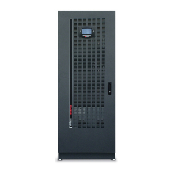
- Page 1 100 & 120kVA UNINTERRUPTIBLE POWER SUPPLY SYSTEM Riello Multi Plus UPS available from EcoPowerSupplies For more information visit: www.ecopowersupplies.com/riello-ups...
- Page 2 NTRODUCTION Thank you for choosing our product. Our company is specialised in designing, developing and manufacturing uninterruptible power supplies (UPS). The UPS described in this manual is a high quality product which has been carefully designed and built in order to guarantee the highest levels of performance.
-
Page 3: Table Of Contents
ONTENTS PRESENTATION INSTALLATION TROUBLESHOOTING TECHNICAL DATA... -
Page 4: Presentation
PRESENTATION FRONT VIEWS Control panel with graphic display Front cover panel with ventilation grilles Door handle Switch cover panel Ventilation grille Ext connection area Communication area... - Page 5 REAR VIEW Upper board level ventilation fans Battery charger/Bypass ventilation fan Compartment ventilation grilles Battery charger/Bypass compartment handle Battery charger/Bypass compartment Bypass fan fuse...
- Page 6 OMMUNICATION AREA EXT CONNECTION AREA VIEW Schuko power share socket Slot for parallel card Schuko power share socket fuse Slot for power relay board Cold start IEC connectors (connected directly to the output) Communication slot 1 Aux switch out contact Communication slot 2 Service bypass R.E.P.O.
- Page 7 ONTROL PANEL VIEW Mains operation LED Replace batteries LED Battery operation LED ECO mode LED Load on bypass LED Graphic display Stand-by / alarm LED F1, F2, F3, F4 = FUNCTION KEYS. The function of each key is shown at the bottom of the display and varies according to the menu.
-
Page 8: Installation
INSTALLATION REPARING FOR INSTALLATION ALL THE OPERATIONS DESCRIBED IN THIS SECTION MUST ONLY BE PERFORMED BY QUALIFIED PERSONNEL. The company does not accept responsibility for damage caused by incorrect connections of by operations not described in this manual. EMOVING THE FROM THE PALLET Upon receipt of the UPS, check that the packaging has not been damaged during transportation. - Page 9 NITIAL CONTENT CHECK After opening the packaging, it is first necessary to check the contents. Identify the accessories box and UPS plinths. Check the content of the accessories box: instruction manual safety manual inspection certificate warranty card ...
- Page 10 NSTALLATION NVIRONMENT When choosing the place of installation of the UPS and the Battery Box, observe the following: avoid dusty environments check that the floor is level and able to support the weight of the UPS and the Battery Box ...
- Page 11 LECTRICAL ONNECTIONS CCESSING THE TERMINALS The following operations must be performed while the UPS is disconnected from the mains, switched off and all the isolating switches on the equipment are open. Before performing connection, open all the machine isolating switches and check that the UPS is completely isolated from all power sources: battery and AC power line.
- Page 12 ONNECTIONS FOR THE MODEL WITH STANDARD BYPASS Proceed as follows in order to open the UPS: open the door remove the switch cover panel (see "UPS front views" point 6) Connect the input and output cables to the terminals as shown in the figure below: OUTPUT: ...
- Page 13 ONNECTIONS FOR THE MODEL WITH SEPARATE BYPASS Connect the input, bypass and output cables as shown in the figure below after removing the jumpers between SWIN and SWBYP: Proceed as follows in order to open the UPS: open the door ...
- Page 14 ONNECTING THE REMOTE MAINTENANCE BYPASS It is possible to install an additional maintenance bypass on a peripheral electrical panel, for example to allow the UPS to be replaced without interrupting the power supply to the load. It is essential to connect the "SERVICE BYPASS" terminal (see "Communication area, ext connection area view") to the auxiliary contact of the SERVICE BYPASS switch.
- Page 15 LECTRICAL SYSTEM CONNECTION DIAGRAMS UPS without variation of the neutral point treatment UPS with input galvanic isolation UPS with output galvanic isolation...
- Page 16 UPS without variation of the neutral point treatment and with separate bypass input Remove the jumpers present between the SWIN and SWBY isolating switches UPS with input galvanic isolation and separate bypass input Remove the jumpers present between the SWIN and SWBY isolating switches UPS with output galvanic isolation and separate bypass input Remove the jumpers present between the SWIN and SWBY isolating switches...
- Page 17 Separate bypass on separate lines: N.B. the input line neutral and the bypass neutral are joined inside the equipment, therefore they must be referred to the same potential. If the two power supply sources are different, is it necessary to use an isolating transformer on one of the inputs.
- Page 18 PROTECTION DEVICES AND SAFETY LECTROMAGNETIC COMPATIBILITY This uninterruptible power supply (UPS) is a product which respects the provisions of class C3 of the standards currently in force as regards electromagnetic compatibility. CAUTION: This product is designed for commercial and industrial application in the second environment – during installation, it may be necessary to add certain restrictions and adopt additional measures in order to prevent disturbances.
- Page 19 BATTERY LINE A protection device against overcurrents and an isolating device must be envisaged on the UPS battery line. The size/type of protection fuse must be chosen based on the capacity of the battery box installed, referring to the table below. External DC protection devices Type of fuse Fuse size...
- Page 20 ESCRIPTION The purpose of a UPS is to guarantee a perfect supply voltage to the equipment connected to it, both when connected to and disconnected from the mains. Once connected and powered, the UPS generates a sinusoidal alternating voltage with stable amplitude and frequency, independent from any sudden changes and/or variations present in the electrical mains.
- Page 21 ONNECTION TO THE ONITORING AND CONTROL SOFTWARE The monitoring software guarantees effective, intuitive UPS management, displaying all the most important information such as input voltage, applied load and battery capacity. It is also capable of performing certain operations automatically i.e. shutdown, sending e-mail, text messages and network messages in order to check particular events selected by the user.
- Page 22 NITIAL OPERATIONS Visual connection check Check that all the connections have been made following the indications given in the "Electrical connections" paragraph to the letter. Check that all the isolating switches are open. Batter fuse holder closure close the switch/fuse of the battery rack (first check the polarity of the connections); CAUTION: if a connection has been made which does not comply with the indications given in the "Electrical connections"...
-
Page 23: S Witching On From The Mains
Press to enter the System on menu. When confirmation is requested, press “YES”, press to confirm and wait for a few seconds. Check that the UPS is set to the state where the load is fed by the inverter. ... -
Page 24: S Witching On From Battery
WITCHING ON FROM BATTERY Make sure that the battery rack switch/fuse is closed. Hold down “Battery Start” (See “Communications View – point 3”) for about 5 seconds. The UPS becomes active and the display comes on. Press ... -
Page 25: G Raphic Display
RAPHIC DISPLAY A wide graphic display is present on the UPS door, which allows the user to have a close-up, detailed overview in real time of the status of the UPS. The user can switch the UPS on and off, consult electrical mains, output, battery measurements etc. - Page 26 ISPLAY MENUS...
-
Page 27: O Perating Modes
PERATING MODES The mode which guarantees maximum load protection is the ON LINE mode, where the energy for the load is subject to a double conversion and is recreated on output in a perfectly sinusoidal way with frequency and voltage fixed by the precise digital control of the DSP independently from the input (V.F.I.). -
Page 28: R Edundant Auxiliary Power Supply For Automatic Bypass
Once maintenance has been completed, perform the following operations in order to restart the UPS: Close the input, output and bypass isolating switches and the battery rack switch/fuse. The signal panel returns to being active. Command the UPS to switch back on from the “SYSTEM ON” menu. Wait until the sequence is complete. - Page 29 R.E.P.O. This isolated input is used to switch off the UPS from a distance in the event of an emergency. The UPS is supplied from the factory with the “Remote Emergency Power Off” (R.E.P.O.) terminals short-circuited (see "communication area"). If installation is necessary, remove the short circuit and connect to the normally closed contact of the locking device using a cable which guarantees a connection with double insulation.
- Page 30 OWER WALK The UPS is equipped as standard with the Power Walk-In mode which can be activated and configured using the UPS Tools software. When the mode is active, once mains voltage comes back (after a period in autonomous mode), the UPS goes back to absorbing power from this source in a progressive way in order to avoid having to oversize any generating set installed upstream from the UPS (due to the breakaway).
-
Page 31: Ups Configuration
CONFIGURATION The table below illustrates all the possible configurations available to the user in order to best adapt the UPS to individual requirements. Indicates that the configuration can be modified from the control panel as well as from the (Control Panel) configuration software. - Page 32 FUNCTION DESCRIPTION DEFAULT POSSIBLE CONFIGURATIONS MODEL Advanced Functions Selects the accepted range ± 0.25% for the input frequency for ± 0.5% Input frequency switching to the bypass and ± 5% ± 0.75% tolerance range for the synchronisation of the ...
-
Page 33: C Ommunication Ports
OMMUNICATION PORTS The UPS is equipped with the following communication ports (see Connections and ext connections views): Serial port, available with RS232 connector and USB connector. N.B. the use of one connector automatically excludes the other. Expansion slot for additional interface cards (COMMUNICATION SLOT) ... - Page 34 AS400 PORT AS400 PORT PIN # NAME TYPE FUNCTION POWER Isolated auxiliary power supply +15V±5% 80mA max Earth to which the isolated auxiliary power supply (15V) and POWER the remote commands (Remote ON, Remote BYPASS, Remote OFF) refer Connecting pin 2 to pin 15 for at least 3 seconds causes the REMOTE ON INPUT #1 UPS to switch on...
- Page 35 UDIBLE SIGNALLING DEVICE UZZER The status and anomalies of the UPS are signalled by the buzzer, which emits a modulated sound depending on the various UPS operating conditions. The various types of sound are described below: Sound A: The signal is emitted when the UPS is switched on or off using the appropriate buttons. A single beep confirms power-on, the activation of the battery test, the cancellation of programmed power-off.
-
Page 36: Troubleshooting
TROUBLESHOOTING Irregular UPS operation is most likely not an indication of a fault but due to simple problems or distraction. It is therefore advisable to consult the table below carefully as it summarises information which is useful for solving the most common problems. - Page 37 PROBLEM POSSIBLE CAUSE SOLUTION THE JUMPER IS MISSING ON THE R.E.P.O. CONNECTOR THE DISPLAY SHOWS Assemble the jumper or check that it is inserted (J13, POINT 5 - “UPS correctly. CONNECTIONS VIEW”) OR IS NOT INSERTED CORRECTLY BYPASS ISOLATING SWITCH Open the isolating switch (SWMB) located behind the (SWMB) FOR MAINTENANCE door.
- Page 38 PROBLEM POSSIBLE CAUSE SOLUTION OPENING OF THE PROTECTION DEVICE Reset the upstream protection device. CAUTION: UPSTREAM FROM THE check that check that no overload or short circuit is BYPASS LINE (ONLY IN THE THE DISPLAY SHOWS present at the UPS output CASE OF CONNECTION WITH ONE OR MORE OF THE SEPARATE BYPASS)
- Page 39 PROBLEM POSSIBLE CAUSE SOLUTION THE DISPLAY SHOWS ONE OR MORE OF THE It is advisable to replace the batteries in the battery rack FOLLOWING CODES: as they are no longer able to maintain their charge for a THE BATTERIES HAVE NOT A39, A40 sufficient period of autonomy.
- Page 40 TATUS ALARM CODES Using a sophisticated self-diagnosis system, the UPS is able to check its own status and any anomalies and/or faults which may occur during operation and display them on the display panel. If there is a problem, the UPS signals the event by showing the code and the type of active alarm on the display.
- Page 41 Anomaly: “minor” problems which do not lock the UPS but reduce levels of performance or prevent the use of certain functions. CODE DESCRIPTION Inverter not synchronised External synchronisation failed Overvoltage on input line of Phase 1 Overvoltage on input line of Phase 2 Overvoltage on input line of Phase 3 Undervoltage of input line of Phase 1 Undervoltage of input line of Phase 2...
- Page 42 Fault: more critical problems than “Anomalies” because if they persist, they could lead to the locking of the UPS in a very short time. CODE DESCRIPTION Internal communication error Cyclical direction of the input phases is incorrect Input fuse of Phase 1 blown or input static switch faulty (does not close) Input fuse of Phase 2 blown or input static switch faulty (does not close) Input fuse of Phase 3 blown or input static switch faulty (does not close) Positive branch capacitator pre-charge failed...
- Page 43 Lock: indicates that the UPS or one of its components has been locked and is normally preceded by an alarm signal. In the event of a fault with and consequent lock of the inverter, it will switch off and the load will be powered by the bypass line (this procedure is excluded for locks due to serious, persistent overloads and short circuits).
-
Page 44: Technical Data
TECHNICAL DATA UPS models 100 kVA 120 kVA Input stage Rated voltage 380-400-415 Vac three-phase with neutral (4 wire) Nominal voltage 50-60Hz Max input current 185 A 216 A Max battery current 254 A 304 A 20% @ 100% load... - Page 45 (PWM regulation of charging current and voltage) Input voltage tolerance range for recharging at 345-480Vac maximum current UPS models 100 kVA 120 kVA Dimensions and weights Width x Depth x Height 750 x 855 x 1900 mm Tower type with wheels, movement with transpallet, display fixed to the top of the Type of structural work door.
Need help?
Do you have a question about the 100 kVA and is the answer not in the manual?
Questions and answers