Table of Contents
Advertisement
Advertisement
Table of Contents

Related Manuals for Riello SENTINEL PRO


Summary of Contents for Riello SENTINEL PRO
- Page 2 NTRODUCTION Congratulations on purchasing a UPS Sentinel Pro product and welcome to Riello UPS! To use the support service offered by Riello UPS, visit the site www.riello-ups.com The company is highly specialised in the development and production of uninterruptible power supplies (UPSs).
-
Page 3: Table Of Contents
ONTENTS PRESENTATION UPS V IEWS RONT VIEW EAR VIEW ISPLAY PANEL VIEW ATTERY ACCESSORY NOT PROVIDED WITH UPS EAR VIEW INSTALLATION NITIAL CONTENT CHECK NSTALLATION ENVIRONMENT ATTERY OX INSTALLATION ETTING THE NOMINAL BATTERY CAPACITY ONNECTIONS AND SWITCHING ON FOR THE FIRST TIME WITCHING ON FROM THE MAINS WITCHING ON FROM THE BATTERY WITCHING OFF THE... - Page 4 TROUBLESHOOTING LARM CODES AULT TECHNICAL DATA...
-
Page 5: Presentation
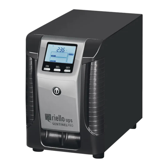
PRESENTATION SENTINEL PRO uses ON-LINE double conversion technology, resulting in the highest levels of reliability and maximum protection for critical loads such as servers, IT applications and Voice/Data. It is possible to use one or more autonomy expansion units known as BATTERY BOXES (optional accessories) with the same dimensions and aesthetic line as the UPS alongside it. -
Page 6: Ups Views
UPS V IEWS RONT VIEW EAR VIEW 700VA / 1500VA model 1000VA / 1000VA ER model Display Cooling fans Multipurpose buttons Battery expansion connector ON/OFF switch IEC 10A output socket RS232 communication port and contacts IEC 10A input plug USB communication port Circuit breaker Slot for communication cards... - Page 7 2200VA model 2200VA ER / 3000VA / 3000VA ER model RS232 communication port and contacts IEC 16A output socket (only for 3000VA models) USB communication port IEC 10A output socket Slot for communication cards IEC 16A input plug Cooling fans IEC 10A input plug Battery expansion connector Circuit breaker...
-
Page 8: Display Panel View
ISPLAY PANEL VIEW “SEL” button (Select) Battery charge indicator “ON” button Load level indicator “STAND-BY” button Configuration area Regulation operation Maintenance request Mains operation Timer Battery operation Measurement display area Load powered by bypass Stand-by / alarm... -
Page 9: Battery Box ( Accessory Not Provided With Ups )
ATTERY ACCESSORY NOT PROVIDED WITH UPS The BATTERY BOX is an optional accessory dedicated to this range of UPSs (same dimensions and aesthetic line). The BATTERY BOX contains batteries which allow the operating time of the uninterruptible power supplies to be increased during extended blackouts. -
Page 10: Installation
INSTALLATION NITIAL CONTENT CHECK After opening the packaging, it is first necessary to check the contents. The package must contain: Schuko power cable - IEC 10A (IEC 16A for 3000VA models only) IEC 16A male plug 2 IEC 10A connection cables (For 3000VA models only) USB cable RS232 cable... -
Page 11: Installation Environment
It is not possible to connect more than one UPS to a single battery box, or to several Battery Boxes connected in a series. To check whether a new version of the most up-to-date software is available, consult the website: www.riello-ups.com. -
Page 12: Use
6) Check which operating mode is set on the display and, if necessary, see the “Configuring operating modes” paragraph to set the required mode. For advanced UPS configurations execute the software UPSTools which can be downloaded from the web site www.riello-ups.com. WITCHING ON FROM THE MAINS 1) Press the “ON”... -
Page 13: Display Panel Messages
ISPLAY PANEL MESSAGES This chapter describes, in detail, the various information that can be displayed on the LCD. STATUS MESSAGES ICON STATUS DESCRIPTION Fixed Indicates a fault Flashing The UPS is in stand-by mode Fixed Indicates regular operation Fixed The UPS is operating from the mains The UPS is operating from the mains, but the output voltage is not Flashing synchronised with the mains voltage... -
Page 14: Measurement Display Area
EASUREMENT DISPLAY AREA It is possible to display the most important measurements regarding the UPS in sequence on the display. When the UPS is switched-on, the display shows the main voltage value. To display a different measurement, press the “SEL” button repeatedly until the desired measurement appears. In the event of a fault/alarm (FAULT) or a lock (LOCK), the display will automatically show the type and code of the corresponding alarm. -
Page 15: Configuring The Operating Mode
ONFIGURING THE OPERATING MODE The area of the display shown in the figure displays the active operating mode and allows the user to choose other modes directly from the display panel. HOW TO PROCEED: To access the configuration area, hold down the “SEL” button for at least 3 seconds. ... -
Page 16: Software
2) Download the software from the web site www.riello-ups.com selecting the specific operating system. 3) Follow the installation program instructions. 4) For more detailed information please read the user manual which can be downloaded from www.riello- ups.com. ONFIGURATION SOFTWARE The UPSTools software allows the configuration and full display of the status of the UPS via USB or RS232. -
Page 17: Ups Configuration
CONFIGURATION The table below illustrates all the possible configurations available to the user in order to best adapt the UPS to individual requirements. It is possible to perform these operations using the Upstools software. FUNCTION DESCRIPTION DEFAULT POSSIBLE CONFIGURATIONS 50 Hz Selects the nominal output ... - Page 18 FUNCTION DESCRIPTION DEFAULT POSSIBLE CONFIGURATIONS Selects permitted Low: 180 - 200 in 1V steps Bypass voltage Low: 180V voltage range for switching High: 250 - 264 in 1V steps thresholds High: 264V to the bypass Selects permitted Low: 180 - 220 in 1V steps Bypass voltage Low:...
-
Page 19: Communication Ports
Serial duplicator Ethernet network card with TCP/IP, HTTP and SNMP protocols JBUS / MODBUS protocol converter card PROFIBUS protocol converter card Card with relay isolated contacts To check whether further accessories are available, consult the website: www.riello-ups.com... - Page 20 TROUBLESHOOTING Irregular UPS operation is most likely not an indication of a fault but due to simple problems or distraction. It is therefore advisable to consult the table below carefully as it summarises information which is useful for solving the most common problems.
- Page 21 The UPS in case of a permanent failure will be not able to supply the load. To ensure total protection of your equipment we suggest you install an ATS device (Automatic Transfer Switch) or an external automatic by-pass. For more information visit www.riello-ups.com...
- Page 22 LARM CODES Using a sophisticated self-diagnosis system, the UPS is able to check its own status and any anomalies and/or faults which may occur during normal operation and display them on the display panel. If there is a problem, the UPS signals the event by showing the code and the type of active alarm on the display (FAULT and/or LOCK).
- Page 23 Active commands: Indicates the presence of an active remote command. CODE DESCRIPTION Remote control 1 (Switch On/Off) Remote control 2 (load on bypass or manual bypass command) Remote control 3 (Switch On/Off) Battery test in progress LOCK alerts are normally preceded by an alarm signal and their scale leads to the power-off of the inverter and the load being powered by the bypass line (this procedure is excluded for locks due to serious, persistent overloads and short circuits).
- Page 24 TECHNICAL DATA SEP 1000 SEP 2200 SEP 3000 UPS MODELS SEP 700 SEP 1500 SEP 1000 ER SEP 2200 ER SEP 3000 ER INPUT Nominal voltage [Vac] 220 - 230 - 240 Maximum operating voltage [Vac] Nominal frequency [Hz] 50 - 60 Nominal current (1) 12.5 BATTERY...
- Page 25 BATTERY BOX JSEP036-NPA- JSEP036-NPM- JSEP072-NPA- JSEP072-NPM- Nominal battery voltage [Vdc] 36Vdc 72Vdc Dimensions W x D x H [mm] 158 x 422 x 235 190 x 446 x 333 Weight [kg] The “-” symbol replaces an alphanumeric code for internal use.
Need help?
Do you have a question about the SENTINEL PRO and is the answer not in the manual?
Questions and answers