Table of Contents
Advertisement
Advertisement
Table of Contents

Related Manuals for Riello MULTI SENTRY MST 60


Summary of Contents for Riello MULTI SENTRY MST 60
- Page 2 NTRODUCTION Thank you for choosing our product. Our company is highly specialised in the development and production of uninterruptible power supplies (UPS). The UPS device described in this manual is a high quality product that has been carefully designed and manufactured to guarantee optimal performance.
-
Page 4: Table Of Contents
ONTENTS PRESENTATION 60 – 80 – 100 – 125 ULTI ENTRY VIEWS RONT VIEW OMMUNICATIONS AREA VIEW WITCHES VIEW EAR VIEW ONTROL PANEL VIEW CONNECTIONS MST 60-80-100 CONNECTIONS MST 125 CONNECTIONS MST 60-80-100) EPARATE YPASS NPUT OPTIONAL FOR INSTALLATION NSTALLATION SET UPS S TORAGE RELIMINARY INFORMATION... - Page 5 UXILIARY CONTACTS XTERNAL TEMPERATURE SENSOR OPTIONAL EMOTE PANEL OPTIONAL UXILIARY SOCKETS OPTIONAL NERGY HARE UX OUTPUT EMOTE MAINTENANCE BYPASS ESCRIPTION IRST START UP AND ADDITIONAL SETTINGS WITCHING ON FROM THE MAINS WITCHING ON FROM THE BATTERY HUTDOWN RAPHIC DISPLAY ISPLAY MENU PERATING MODE (SWMB) ANUAL BYPASS...
-
Page 6: Presentation
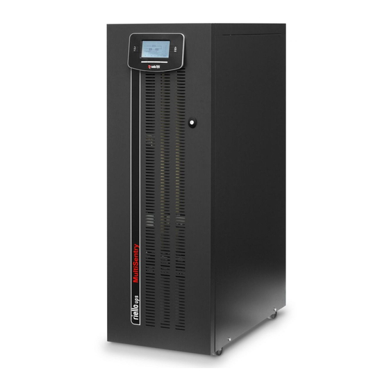
PRESENTATION 60 – 80 – 100 – 125 ULTI ENTRY MST 60 – 80 – 100 – 125 series UPS have been designed using currently available state of the art technology to ensure maximum performance. The use of new control boards based on multiprocessor architecture (DSP + P) and of special circuit solutions employing the latest generation of components has enabled us to achieve high performance such as: ... -
Page 7: Ups Views
VIEWS RONT VIEW Control panel with graphic display Wheels for UPS handling Front door with lock Parking brakes Ventilation grille... -
Page 8: Communications Area View
OMMUNICATIONS AREA VIEW “R.E.P.O.” Remote Emergency Power Off “COLD START” battery start-up button “AS400” Contacts port “USB” communication port “RS232” communication port “UPS Parallel Board” housing (optional) Slot for communication accessory boards... -
Page 9: Switches View
WITCHES VIEW “SWIN” Input switch “SWOUT” Output switch “SWBYP” Separate bypass switch (optional) “QN” Switch for service personnel use only “SWMB” Manual bypass switch Terminal cover (MST 60-100) / bar cover (MST 125) -
Page 10: Rear View
EAR VIEW “EnergyShare / Aux Output” sockets (10A max.) Power board fans and relative protection (optional) “MultiCOM contacts board” accessory Battery charger fan housing... -
Page 11: Control Panel View
ONTROL PANEL VIEW Mains operation LED On steady: mains operation with good bypass line and synchronised inverter Flashing: mains operation with bad or disabled bypass line and/or non-synchronised inverter Flashing in standby: programmed restart function active and mains present Battery operation LED ... -
Page 12: Ups Connections View
CONNECTIONS MST 60-80-100 CONNECTIONS Removing the terminal cover panel to access the UPS terminal board: BATT (+ -) Power connections: (+) and (-) BATTERY INPUT (L1 L2 L3) Power connections: INPUT PHASES BYPASS (L1 L2 L3) Power connections: SEPARATE BYPASS PHASES (optional) OUTPUT (L1 L2 L3) Power connections: OUTPUT PHASES Power connections: N BATTERY, N INPUT, N BYPASS, N OUTPUT... -
Page 13: Mst 125 Connections
MST 125 CONNECTIONS Remove the bar cover to access the UPS's connections: BATT (+ -) Power connections: (+) and (-) BATTERY INPUT (L1 L2 L3) Power connections: INPUT PHASES BYPASS (L1 L2 L3) Power connections: SEPARATE BYPASS PHASES OUTPUT (L1 L2 L3) Power connections: OUTPUT PHASES Power connections: N BATTERY, N INPUT, N BYPASS, N OUTPUT Power connections: GROUND... -
Page 14: Separate Bypass Input ( Optional For Mst 60-80-100)
MST 60-80-100) EPARATE YPASS NPUT OPTIONAL FOR THE "DUALINPUT" UPS SERIES VERSION PRESENTS THE BYPASS LINE SEPARATE FROM THE INPUT LINE. The UPS series with Separate Bypass allows a separate connection between the input line and the bypass line. The UPS output will be synchronized to the bypass line in such a way that there will not be any incorrect switching between push- pull voltages in the event of automatic bypass intervention or manual bypass (SWMB) closing. -
Page 15: Installation
INSTALLATION NSTALLATION SET ALL OPERATIONS DESCRIBED IN THIS SECTION MUST BE PERFORMED BY QUALIFIED PERSONNEL ONLY. Our Company assumes no liability for damages caused by incorrect connections or operations not contained in this manual. UPS S TORAGE The storage site must meet the following requirements: Temperature: -25°÷60°C Degree of relative humidity:... -
Page 16: Electromagnetic Compatibility
LECTROMAGNETIC COMPATIBILITY This UPS complies with applicable EMC (Category C3). ATTENTION: This product is designed for second environment* commercial and industrial applications - it may be necessary during installation to introduce certain restrictions and take additional measures to prevent disturbances. Connection to USB and RS232 connectors must be made with the supplied cables or, however, with shielded cables that are no longer than 3 metres. -
Page 17: Removing The Ups From The Pallet
EMOVING THE FROM THE PALLET ATTENTION: FOLLOW THE INSTRUCTIONS BELOW TO AVOID PERSONAL INJURY AND/OR EQUIPMENT DAMAGE. SOME OF THE FOLLOWING OPERATIONS REQUIRE THE INTERVENTION OF TWO PEOPLE Cut straps and remove from the cardboard box. Remove the 2 brackets fastening the UPS to the pallet, Remove the packaging material. -
Page 18: Content Check
ONTENT CHECK It is first necessary to check the contents after the packaging has been opened: steel slide, warranty card, instructions manuals, safety manual, inspection certificate, serial connection cable, keys for door lock. UPS P OSITIONING When positioning, take into account that: ... -
Page 19: Electrical Connections
LECTRICAL CONNECTIONS ONNECTION CABLES SECTION Refer to the following table for the sizing of input, output and battery cables: Sezione cavi (mmq) INPUT OUTPUT EXTERNAL BATTERY network / separate bypass (optional) L1/L2/L3 L1/L2/L3 The sections contained in the table refer to a maximum length of 10 m (cable type N07V-K in clear air) The maximum length of the connection cables to the Battery Box is 10 metres In the case of non-linear loads, oversize neutral line N by 1.7 times the phase line Note MST 60: the maximum section of the cables that can be inserted in the terminal board is equal to 50 mm2 (flexible and... -
Page 20: Preliminary Operations For Connection
At the bottom of the units is a holed bar that can be used for a steady anchor for the cables by means of appropriately sized clamps. Notes: Tighten down the clamp only after securing the cables to their terminals/bars. Preform the cables so that the terminals/bars are not stressed when you tighten down the clamp. -
Page 21: Hookup Instructions
OOKUP INSTRUCTIONS Follow the instructions below in order: open the door Depending on model: remove the terminal/bar cover (see "Switches view") MST 125: to remove the bar cover, first remove the handles of the SWIN, SWOUT, SWBYP and SWMB switches by undoing their screws as shown in the image. -
Page 22: Electrical System Connection Diagrams
LECTRICAL SYSTEM CONNECTION DIAGRAMS UPS without neutral connectivity variation UPS with galvanic input insulation UPS with galvanic output insulation... - Page 23 UPS without neutral connectivity variation and with separate bypass input UPS with galvanic input insulation and with separate bypass input UPS with galvanic output insulation and with separate bypass input...
- Page 24 Separate bypass on separate lines: if the separate bypass option is present, all protective devices will have to be placed both on the main supply line and on the line dedicated to the bypass. Note: the input line and bypass line neutral are shared inside the device; therefore, they will have to be connected to the same potential.
-
Page 25: Protection Devices
ROTECTION DEVICES HORT CIRCUIT PROTECTION In the presence of a fault on the load, the UPS limits the value and duration of the output current (short circuit current) for protection. These values are also functions of unit status at the time of the fault. Two different cases can be distinguished: ... -
Page 26: Differential
IFFERENTIAL In the absence of an input separating transformer, the neutral from the mains power supply is connected to the neutral of the UPS output. This way the neutral regime of the equipment is not modified. THE INPUT NEUTRAL IS CONNECTED TO THE OUTPUT NEUTRAL THE DISTRIBUTION SYSTEM THAT POWERS THE UPS IS NOT MODIFIED BY THE UPS WARNING: make sure that the equipment is connected correctly to the input neutral, or else damages to the UPS may be caused. -
Page 27: Output Line Fuses / Thermal Magnetic Switches
UTPUT LINE FUSES THERMAL MAGNETIC SWITCHES Output protections (recommended values for selectivity) MST 60 – MST 80 – MST100 MST 125 Normal fuses (gL-gG) In (Nominal current)/7 In (Nominal current)/4 Thermal magnetic switches (C Curve) In (Nominal current)/7 In (Nominal current)/4 R.E.P.O. -
Page 28: External Sync
XTERNAL This non-isolated input is used to synchronize the inverter output with a suitable signal coming from an external source. To install: use an isolation transformer with isolated single-phase output (SELV) within range 12-24V AC with 0.5VA power ... -
Page 29: External Temperature Sensor ( Optional )
XTERNAL TEMPERATURE SENSOR OPTIONAL This NON-ISOLATED input is used to detect temperature inside a remote Battery Box. Only use the special kit (optional) supplied by the manufacturer: any uses which do not conform to specifications may cause malfunction or equipment breakage. For installation, connect the cable contained in the special kit (optional) to the "EXT BATT TEMP"... -
Page 30: Remote Maintenance Bypass
EMOTE MAINTENANCE BYPASS Attention: carefully read the “Manual bypass (SWMB)” paragraph A maintenance bypass (manual bypass) can be installed additionally on a peripheral electrical board (see following diagram). This allows, for example, UPS replacement without interrupting power to the load. The "SERVICE BYPASS"... -
Page 31: Use
ESCRIPTION The purpose of the UPS is to ensure perfect supply voltage to the equipment connected to it, both in the presence and absence of mains power. Once connected and powered, the UPS generates alternating sinusoidal voltage with stable range and frequency, regardless of sudden changes and/or variations on the mains power. -
Page 32: First Start - Up And Additional Settings
IRST START UP AND ADDITIONAL SETTINGS ATTENTION : the QN switch is for Service personnel use only and must remain closed with its safety lock. Only the following switches can be handled: SWIN, SWBYP (if present), SWOUT, external UPS battery line switch and, necessary, SWMB (see paragraph “Manual bypass (SWMB)”) ... - Page 33 Wait a few seconds after SWIN closing. Check that the display switches on and that the UPS is set to "STAND-BY" mode. Follow the instructions below if a message indicating an erred phase cycle direction appears on the display: ...
-
Page 34: Switching On From The Mains
WITCHING ON FROM THE MAINS Close the SWIN and SWBYP input switches (if present) and leave the SWMB manual bypass switch open. After a few seconds, the UPS will switch on and the "Stand-by / alarm" LED will flash: the UPS is now in stand-by status. ... -
Page 35: Graphic Display
RAPHIC DISPLAY At the centre of the control panel is a wide graphic display for a constant detailed, real-time overview of UPS status. The first page is a schematic view of UPS operating status: Input Line Battery Charger Line PFC Converter Battery Line Inverter % Load... - Page 36 In addition, the user can switch the UPS on/Off directly from the control panel, consult network, output, battery measurements, etc. and make the main machine settings. The display is sub-divided into four main zones, each with its own specific role. Graphic display sample screens (screens for demonstration purposes;...
-
Page 37: Display Menu
ISPLAY MENU... -
Page 38: Operating Mode
PERATING MODE The mode that ensures the most load protection is the ON LINE mode, where power for the load undergoes a couple conversion and is reconstructed at output in a perfectly sinusoidal way, with frequency and voltage fixed by the precise digital control of the DSP independently from the input (V.F.I.). -
Page 39: Redundant Auxiliary Power Adapter For Automatic Bypass
EDUNDANT AUXILIARY POWER ADAPTER FOR AUTOMATIC BYPASS The UPS is equipped with a redundant auxiliary power adapter which permits operation on the automatic bypass even in the event of main auxiliary power faults. In the event of a UPS fault, which also can cause breakage of the main auxiliary power, the load remains powered by means of the automatic bypass. -
Page 40: Ups Configuration
CONFIGURATION Configurations which can be modified by the user from the control panel are listed in the table below. FUNCTION DESCRIPTION DEFAULT POSSIBLE CONFIGURATIONS English Spanish Italian Polish Selects mimic panel Language* English German Russian language language ... - Page 41 FUNCTION DESCRIPTION DEFAULT Selects the synchronisation speed of the inverter to the Bypass Synchronization speed 1 Hz/sec bypass line External synchronization Selects the source of synchronisation for the inverter output From bypass line External temperature Activates reading of the external temperature probe Disabled Enabled / Bypass mode...
-
Page 42: Communication Ports
OMMUNICATION PORTS The following communication ports are present on the upper part of the UPS behind the door (see "Communications area view"): Serial port, available with RS232 and USB connectors. NOTE: use of one connector automatically excludes the other ... -
Page 43: As400 Port
AS400 P AS400 PORT PIN # NAME TYPE FUNCTION POWER Isolated auxiliary power +15V±5% 80mA max Mass to which isolated power supplies (15V) and remote POWER controls (Remote ON, Remote BYPASS, Remote OFF) are referred Connect pin 2 with pin 15 for at least 3 seconds to switch on REMOTE ON INPUT #1 the UPS... -
Page 44: Acoustic Signal (Buzzer )
COUSTIC SIGNAL UZZER UPS status and faults are signalled via a buzzer which emits a modulated sound depending on different UPS operating conditions. The different types of sounds are described below: Sound A: This signal is emitted when the UPS is switched on or off using the appropriate buttons. A single beep confirms ON, battery test activation, the cancellation of programmed shutdown. -
Page 45: Software
UPS USB port to a PC USB port via a standard USB cable*. Follow the installation program instructions. For further information regarding installation and user, consult the software manual which can be downloaded at www.riello- ups.com. ONFIGURATION SOFTWARE It is possible to access the most important UPS parameter configuration by means of special software. -
Page 46: Troubleshooting
TROUBLESHOOTING Irregular UPS operation is most likely not an indication of a fault but due to simple problems or distraction. It is therefore advisable to consult the table below carefully as it summarises information which is useful for solving the most common problems. - Page 47 PROBLEM POSSIBLE CAUSE SOLUTION NO JUMPER ON R.E.P.O. Connect or properly insert jumper. If present, verify that CONNECTOR (SEE THE DISPLAY SHOWS "COMMUNICATIONS AREA optional emergency contact complies with VIEW") OR JUMPER NOT information detailed in the R.E.P.O. paragraph INSERTED PROPERLY If the switch (SWMB) located behind the door was not MANUAL BYPASS SWITCH (SWMB) CLOSED...
- Page 48 PROBLEM POSSIBLE CAUSE SOLUTION BYPASS LINE UPSTREAM Reset upstream protection. ATTENTION: check that PROTECTION OPEN (WITH there is no output overload or short circuit to the UPS. THE DISPLAY SHOWS SEPARATE BYPASS ONLY) ONE OR MORE OF THE FOLLOWING CODES: BYPASS SWITCH OPEN A13, A14, A15 Close switch located behind the door.
- Page 49 PROBLEM POSSIBLE CAUSE SOLUTION THE DISPLAY SHOWS ONE OR MORE OF THE It is advisable to replace UPS batteries since they are no FOLLOWING CODES: BATTERIES HAVE NOT longer able to maintain load for a sufficient autonomy. A39, A40 PASSED THEIR PERIODIC Attention: Battery replacement must be performed EFFICIENCY TEST AND THE RED...
-
Page 50: Status / Alarm Codes
TATUS ALARM CODES Using a sophisticated self-diagnosis system, the UPS is able to check and signal its own status and any anomalies or faults which may occur during normal operation. If there is a problem, the UPS signals the event by showing the code and the type of active alarm on the display. - Page 51 ANOMALY: these are “minor” problems which reduce UPS performance or prevent certain functions from being used. CODE DESCRIPTION Inverter not synchronized External synchronization failed Overvoltage on Phase1 input line Overvoltage on Phase2 input line Overvoltage on Phase3 input line Undervoltage on Phase1 input line Undervoltage on Phase2 input line Undervoltage on Phase3 input line...
- Page 52 FAULT: these are more critical problems than the "Anomaly" faults because, if they persist, they could cause the UPS to lock within a very short time. CODE DESCRIPTION Internal communication error Incorrect input phase cycle direction Phase1 input fuse broken or input contactor locked (does not close) Phase2 input fuse broken or input contactor locked (does not close) Phase3 input fuse broken or input contactor locked (does not close) Phase1 input contactor locked (does not open)
- Page 53 LOCK: Indicates an inhibit of the UPS or a component caused by a failure. A lock is normally preceded by an alarm. In the event of a fault and consequential inverter lock, the inverter will switch off and power to the load via the bypass line (this procedure is excluded for locks caused by serious and persistent overloads and for those caused by a short circuit).
-
Page 54: Technical Data
TECHNICAL DATA UPS Models MST 60 MST 80 MST 100 MST 125 INPUT STAGE Nominal Voltage 380-400-415 V AC Three-phase with neutral (4 wire) Nominal Frequency 50-60Hz 155A Maximum input current 125A 211A 250A Maximum battery current 150A 200A 300A Input voltage tolerance accepted for ... - Page 55 UPS Models MST 60 MST 80 MST 100 MST 125 MODE AND EFFICIENCY True on line double conversion Eco mode Operating mode Smart Active mode Stand By Off (Emergency power supply) Frequency Converter AC/DC yield in Eco mode > 99% OTHER ≤...
Need help?
Do you have a question about the MULTI SENTRY MST 60 and is the answer not in the manual?
Questions and answers