Table of Contents
Advertisement
Advertisement
Table of Contents

Related Manuals for Riello Sentinel Dual SDL 3300


Summary of Contents for Riello Sentinel Dual SDL 3300
- Page 2 SAFETY USER’S MANUAL...
- Page 3 Thanks you for choosing this product of the Sentinel Dual range. Riello UPS are renowned specialists in the development and production of uninterruptible power supplies (UPS). The UPS in this range are high quality products, designed and built with care in order to give you the best performance.
-
Page 4: Table Of Contents
ONTENTS RESENTATION VIEWS DISPLAY MASK VIEW NSTALLATION PENING THE PACKING AND CHECKING CONTENTS TOWER VERSION RACK VERSION ONNECTIONS AND SWITCHING ON FOR THE FIRST TIME WITCHING ON FROM THE MAINS WITCHING ON FROM THE BATTERY WITCHING THE ISPLAY ANEL NDICATIONS UPS status indicators Measurements display area Configuration area... -
Page 5: Presentation
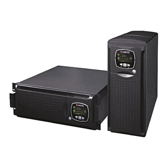
RESENTATION The new Sentinel Dual UPS family has been designed with a special eye to versatility. These UPS, depending on the user’s requirements, can in fact be installed either in tower version or in rack version (by means of a suitable handles kit option). The 2 different product versions are shown below: Tower Rack The UPS also has a dedicated battery pack that permits easy replacement of the batteries (hot swap), entirely... -
Page 6: Ups Views
RESENTATION VIEWS Release slots Extractable/rotatable display mask Manual bypass General switch switch Cable with Removable front terminal panel Battery pack Front view (front panel off) (front panel on) RS232 communication port communication port COMMUNICATION SLOT Expansion slot Input thermal protection Cooling fans IEC 16A Inlet... -
Page 7: Display Mask View
RESENTATION DISPLAY MASK VIEW “SEL / SET” button “ON” button “STBY” button Display Operating normally Configuration area Operating on mains power Maintenance action required Operating on battery power Timer Load powered from bypass Measurements display area Battery back-up indicator Stand-by/alarm Load level indicator... -
Page 8: Installation
NSTALLATION PENING THE PACKING AND CHECKING CONTENTS After opening the pack, the first thing to do is make a check of the contents. The pack should contain: 2 plastic covers (top panels) 2 plastic keys Power cord ... -
Page 9: Tower Version
NSTALLATION TOWER VERSION This chapter describes the work needed to prepare the UPS for use in tower version. WARNING: for your own safety and that of your product, it is important that you follow the instructions given below exactly. BEFORE PROCEEDING TO PERFORM THE SEQUENCE OF OPERATIONS DESCRIBED, MAKE SURE THAT THE UPS IS SWITCHED OFF COMPLETELY AND IS NOT CONNECTED TO THE ELECTRICAL MAINS OR LOAD OF ANY KIND... -
Page 10: Rack Version
NSTALLATION RACK VERSION This following describes the work needed to convert the UPS into rack version. WARNING: for your own safety and that of your product, it is important that you follow the instructions given below exactly. BEFORE PROCEEDING TO PERFORM THE SEQUENCE OF OPERATIONS DESCRIBED, MAKE SURE THAT THE UPS IS SWITCHED OFF COMPLETELY AND IS NOT CONNECTED TO THE ELECTRICAL MAINS OR LOAD OF ANY KIND... -
Page 11: Use
ONNECTIONS AND SWITCHING ON FOR THE FIRST TIME Install upstream of the apparatus a 16A magneto-thermal switch with intervention curve B or C. Connect the power cord supplied with the UPS to the IEC 16A inlet socket. Connect the power cord from the UPS to the mains. Press the main switch on the front panel. -
Page 12: Isplay Anel Ndications
ISPLAY ANEL NDICATIONS This chapter will describe in depth all the items of information that may be posted on the LCD. For easier understanding, we can divide the information displayed into three main groups: UPS status indicators Measurements display area ... -
Page 13: Measurements Display Area
Measurements display area The most important measurements relating to the UPS may be displayed on the display screen. When the UPS is switched on, the display shows the mains voltage value. To move on to display something else, press the “SEL / SET” button repeatedly until the desired measurement value appears. - Page 14 The values given in the pictures of the table are purely indicative. The FAULT / LOCK codes will only be displayed if they are active at that time (in presence of a failure/alarm or machine stoppage).
-
Page 15: Configuration Area
Configuration area The configuration area contains the main operating parameters of the UPS and displays its current status. The parameters found in this area can be modified by taking action directly from the display panel. SETTABLE PARAMETERS: Frequency: output voltage frequency Frequency Voltage: Output voltage ... -
Page 16: Modes Of Operation
ODES OF OPERATION The mode that gives the load maximum protection is ON LINE mode (default), where the energy intended for the load undergoes a double conversion and is reconstructed on the output in a perfectly sinusoidal way with frequency and voltage fixed by the precision digital control provided by a microprocessor fully independently of the input (V.F.I.). -
Page 17: Ups Configuration
UPS C ONFIGURATION The following table illustrates all the possible configurations that users have at their disposal to best adapt the UPS to their needs. LEGEND: Indicates that the configuration can be modified, both via the configuration software supplied and also by means of action on the display panel. Indicates that the configuration can be modified only through the configuration software supplied. - Page 18 FUNCTION DESCRIPTION PREDEFINED POSSIBLE CONFIGURATIONS MODE Disabled Time interval for the Battery test 40 hours 1 ÷ 1000 in steps of 1 hour automatic battery test Alarm threshold Disabled Selects the overload for maximum Disabled 0 ÷ 103 in steps of 1% user limit load Selects the level of...
-
Page 19: Communication Ports
OMMUNICATION PORTS The following communication ports are found on the rear of the UPS (see UPS Views): RS232 connector USB connector Expansion slots for additional COMMUNICATION SLOT interface cards RS232 and USB connectors RS232 CONNECTOR USB CONNECTOR PIN # SIGNAL PIN #... -
Page 20: Software
USB port on the UPS to a USB port on the PC using a USB standard cable*. Download the software from www.riello-ups.com, selecting the desired operating system. Follow the installation program instructions. -
Page 21: Attery Pack
ATTERY PACK EPLACEMENT OF THE BATTERY PACK As indicated in the presentation, the UPS is provided with a dedicated battery pack that permits easy replacement of the batteries (hot swap), entirely safely for the operator, thanks to the protected connection system. -
Page 22: Problem Solving
ROBLEM SOLVING Very often improper operation of the UPS does not indicate a failure, but is due solely to banal problems, drawbacks or lack of attention. You are therefore recommended to carefully consult the table below which summarizes the information needed to solve the most common problems. - Page 23 ROBLEM SOLVING PROBLEM POSSIBLE CAUSE SOLUTION THE BUZZER SOUNDS CONTINUOUSLY AND THE Lower the load to inside the 100% threshold (or user THE LOAD APPLIED TO THE DISPLAY POSTS ONE OF UPS IS TOO HIGH threshold in case of code A54). THE CODES: A54, F50, F51, F52, F55, L50, L51, L52 Replace the battery pack with a new one (as indicated in...
-
Page 24: Alarm Codes
ROBLEM SOLVING LARM CODES By using a sophisticated self-test system, the UPS can check and report on the display panel any problems and/or failures that could occur during normal operation of the equipment. In case of a problem, the UPS signals the event by posting on the display the code and type of alarm present (FAULT and/or LOCK). - Page 25 ROBLEM SOLVING Commands in progress: Indicates presence of a remote command in progress. CODE DESCRIPTION Remote shutdown command Remote load on bypass command Remote switch-on command Battery test in progress LOCK The LOCK (block) type report signals are usually preceded by an alarm signal and, on account of their importance, result in the inverter being switched off and the load being powered through the bypass line (the procedure is excluded in case of lockouts due to strong and persistent overloads and lockouts following a short-circuit).
-
Page 26: Technical Data Table
ECHNICAL DATA TABLE MODELS SDL 3300 SDL 4000 INPUT Nominal voltage [Vac] 220 / 230 / 240 Accepted range [Vac] 0 ÷ 276 Voltage range ruling out battery intervention [Vac] Maximum: 276 [Vac] Minimum: 164 ÷ 84 (from 100% to 50% of load in linear mode) [Vac] Return to mains-powered operation: 180... -
Page 27: Ferrite Installation Addendum
ECHNICAL DATA TABLE OPERATION POWERED BY OVERLOAD TIMES BYPASS INVERTER Activates bypass after 2 sec 100% < Load 110% Stoppage after 60 sec Stoppage after 120 sec Activates bypass after 2 sec 110% < Load 150% Stoppage after 4 sec Stoppage after 4 sec Activates bypass instantaneously Load >...
Need help?
Do you have a question about the Sentinel Dual SDL 3300 and is the answer not in the manual?
Questions and answers