
Related Manuals for SOLE f60


Summary of Contents for SOLE f60
- Page 1 OWNER’S MANUAL PLEASE CAREFULLY READ THIS ENTIRE MANUAL BEFORE OPERATING YOUR NEW TREADMILL!
-
Page 2: Table Of Contents
Table of Contents Safety hints…………………………………………………………………………2 Introduction………………………………………………………... ………………3 Specifications……………………………………………………………………….3 Assembly Pack Check List List……………………………………………………4 Assembly Instructions………………………………………………………………6 Folding Instructions…………………………………………………………………10 Transport Instructions………………………………………………………………10 Operation of Your Treadmill…………………………………………………..……11 Programmable Features……………………………………………………………15 General Maintenance…………………………………………………………..…...22 Service Checklist-Diagnosis Guide…………………………………………..……25 Exploded View Diagram…………………………………………... ……………….27 Parts List….………………………………..……………………..…………………..28 ST90-YT007_1208(SL)A... -
Page 3: Safety Hints
Safety hints IMPORTANT: THIS UNIT IS INTENDED FOR HOUSEHOLD USE ONLY SAFETY PRECAUTIONS Thank you for purchasing our product. Even though we go to great efforts to ensure the quality of each product, occasional errors and/or omissions do occur. In any event should you find this product to be defective or missing a part please contact our Customer Service Department. -
Page 4: Introduction
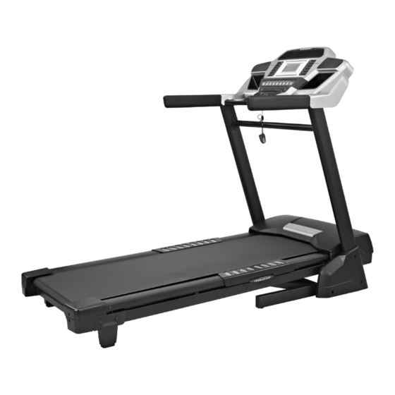
Introduction The treadmill has been designed and constructed to provide trouble free usage and enjoyable exercise. You can greatly improve your understanding and benefits of exercising by carefully reading the instructions given in this manual. Please familiarize yourself with the maintenance advice provided for you. Specifications Drive Motor: 2.75 hp •... -
Page 5: Assembly Pack Check List List
Assembly Pack Check List #97. 5/16" × 1/2" #76. Ø5/16" × Ø18 × 1.5T Hex Head Bolt (8pcs) Flat Washer (8 pcs) #95. M5 × 15m/m #93. Ø10 Phillips Head Screw (6 pcs) Split Washer (4 pcs) #94. 3/8" × 1-1/2" Button Head Socket Bolt (4pcs) #96. - Page 6 #98. Combination M5(25 × 90m/m) #99. M6(68 × 88) Allen Wrench & Phillips Head Screw Allen Wrench (1pc) Driver (1pc) #100. 13m/m Wrench (1pc)
-
Page 7: Assembly Instructions
Assembly Instructions Step 1. Remove the unit from the box and put it on a flat and level floor. Step 2. Connect Computer Cable (Upper/Lower) (44) with Computer Cable (Middle) (43) then insert Right and Left Uprights (4) and (5) into the Frame Base (2) and use 13m/m Wrench (100) to tighten 8 pcs of 5/16" ×1/2"... - Page 8 Step3. Install Frame Base Cover (L) and (R),(33) and (34), on the Frame Base (2) and secure with 6 pcs of M5 × 15m/m Phillips Head Screws (95) by using Combination M5 Allen Wrench & Phillips Head Screw Drive (98). Step4.
-
Page 9: Insert Console Assembly (19) Into Right And Left Uprights (4) And (5) And Secure With 4 Pcs Of
Step5. Insert Console Assembly (19) into right and left Uprights (4) and (5) and secure with 4 pcs of 3/8" × 1-1/2" Button Head Socket Bolts (94) with 4 pcs of Ø10 Split Washers (93) by using M6(68 × 88)Allen Wrench (99). - Page 10 Step7. Put left and right Drink Bottle Holders (19-3) and (19-4) in their places on the Console Assembly (19). 19-4 19-3 NOTE: Please Tighten All Screws After All Components Assembly Complete.
-
Page 11: Folding Instructions
Folding instructions Do not attempt to move the unit unless it is in the folded and locked position. Be sure the power cord is secured to avoid possible damage. Use both handrails to maneuver the unit to the desired position. TO FOLD THE TREADMILL Lift the deck until the latch clicks in place. -
Page 12: Operation Of Your Treadmill
Operation of Your Treadmill Getting familiar with the control panel Console GETTING STARTED CONSOLE : Power the treadmill on by plugging it into an appropriate wall outlet, then turn on the power switch located at the front of the treadmill below the motor hood. Ensure that the Safety Key is installed, as the treadmill will not power on without it. -
Page 13: Incline Feature
QUICK-START OPERATION 1. Attach the Safety Key to wake the display up (if not already on). 2. Press the Start key to begin belt movement then adjust to the desired speed using the Speed keys on the console. You may also use the Quick speed keys 1, 2, 4, 6, 8, or 10 to adjust the speed. 3. -
Page 14: Calorie Display
DOT MATRIX CENTER DISPLAY Twenty columns of dots (8 high) indicate each segment of a workout. The dots are only to show an approximate level (speed/incline) of effort. They do not necessarily indicate a specific value - only an approximate percent to compare levels of intensity. In operation, the speed/incline dot matrix window will build a profile “picture”... - Page 15 PULSE FEATURE The Pulse (Heart Rate) Window will display your current heart rate in beats per minute during the workout. You must use both stainless steel sensors on the front cross bar to display your pulse or wear the wireless chest strap.
-
Page 16: Programmable Features
PROGRAMMABLE FEATURES The F60 has ten built-in programs: one Manual program, five preset profiles, two user defined programs (U1 & U2) and two Heart Rate programs (HR1 & HR2). Hill The Hill program simulates going up and down a hill. The workload will steadily increase and then decrease during the program. -
Page 17: Selecting A Program
SELECTING A PROGRAM 1. Press the Speed keys to view the programs on the screen then press the Enter key to select the program you would like to perform. The display will prompt you through the programming steps or you can just press the Start key to begin the program using the preset program values for age, weight and other program specific information. -
Page 18: User Programs
USER PROGRAMS Select User 1 or User 2 via the Speed keys then press Enter. Note that the dot matrix display portion will have a single row of dots at the bottom (Unless there is a previously stored program). If there is a program stored under the button that is pressed, it will be retrieved. -
Page 19: Heart Rate Programs
Heart Rate programs Before we get started, a word about Heart Rate: The old motto, “no pain, no gain”, is a myth that has been overpowered by the benefits of exercising comfortably. A great deal of this success has been promoted by the use of heart rate monitors. With the proper use of a heart rate monitor, many people find that their usual choice of exercise intensity was either too high or too low and exercise is much more enjoyable by maintaining their heart rate in the desired benefit range. - Page 20 RATE OF PERCEIVED EXERTION Heart rate is important but listening to your body also has a lot of advantages. There are more variables involved in how hard you should workout than just heart rate. Your stress level, physical health, emotional health, temperature, humidity, the time of day, the last time you ate and what you ate, all contribute to the intensity at which you should workout.
- Page 21 USING HEART RATE TRANSMITTER(Optional) How to wear your wireless chest strap transmitter: Attach the transmitter to the elastic strap using the locking parts. Adjust the strap as tightly as possible as long as the strap is not too tight to remain comfortable. Position the transmitter with the logo centered in the middle of your body facing away from your chest (some people must position the transmitter slightly left of center).
- Page 22 HEART RATE CONTROL PROGRAMMING CAUTION! Heart Rate Control programs are intended for wireless transmitter chest strap. Do not use Pulse Grip bar for Heart Control. You must receive a strong/steady value in the heart rate window (See Using Heart Rate Transmitter section for instrucions on how to use). The HR1 program has a default level that is 60% of your projected heart rate maximum.
-
Page 23: General Maintenance
GENERAL MAINTENANCE BELT & DECK Your treadmill uses a very high-efficient low-friction deck. Performance is maximized when the deck is kept as clean as possible. Use a soft,damp cloth,or paper towel,wipe the edge of the belt and the area between the belt edge and the frame. Also reach as far as practical directly under the belt edge. - Page 24 TREAD-BELT TRACKING ADJUSTMENT The treadmill is designed so that the tread-belt remains reasonably centered while in use. It is normal for some belts to drift near one side while in use, depending on a user’s gait and if they favor one leg. But if during use the belt continues to move toward one side, adjustments arenecessary. TO SET TREAD-BELT TRACKING A 6 mm Allen wrench (99)is provided for this adjustment.
- Page 25 BELT/DECK LUBRICATION Keeping the deck lubricated at the recommended intervals ensures the longest life possible for your treadmill. If the lubricant dries out, the friction between the belt and deck rises and places undue stress on the drive motor, drive belt and electronic motor control board, which could result in catastrophic failure of these expensive components.
-
Page 26: Service Checklist-Diagnosis Guide
SERVICE CHECKLIST – DIAGNOSIS GUIDE Before contacting your dealer for aid, please review the following information. It may save you both time and expense. This list includes common problems that may not be covered under the treadmill’s warranty. ROBLEM SOLUTION/CAUSE Display does not light 1.Tether cord not in position. - Page 27 CALIBRATION PROCEDURE 1. Remove the Safety Key. 2. Press and hold down the Start and Speed buttons and replace the Safety Key. Continue to hold the Start and Speed key until the window displays “Factory settings”, then press the Enter key. 3.
-
Page 28: Exploded View Diagram
EXPLODED VIEW DIAGRAM -27-... -
Page 29: Parts List
PARTS LIST Part Number Part Description Qty per unit Main Frame Frame Base Incline Bracket Right Upright Left Upright Console Support Outer Slide Inner Slide Handrail Support Foot Pad Plate Drive Belt Front Roller W/Pulley 12~3 Magnet Rear Roller Running Deck Running Belt Motor Incline Motor... - Page 30 Part Number Part Description Qty per unit Top Motor Cover Plate Rubber Foot Belt Guide Motor Cover Anchor Rear Adjustment Base (L) Rear Adjustment Base (R ) Rear Foot Cover (L) Rear Foot Cover (R) Motor Bracket Inner Slide End Cap Transportation Wheel End Cap Frame Base Cover (L) Frame Base Cover (R)
- Page 31 Part Number Part Description Qty per unit M6 × 25m/m_Flat Head Countersink Bolt M8 × 12m/m_Hex Head Bolt 3/8"_Nyloc Nut 5/16"_Nyloc Nut M8_Nyloc Nut Ø25 × Ø10 × 2.0T_Flat Washer Ø19 × Ø10 × 1.5T_Flat Washer Ø5/16" × Ø18 × 1.5T_Flat Washer Ø1/4"...
- Page 32 Part Number Part Description Qty per unit 3 × 8m/m_Sheet Metal Screw 1000m/m_Ground Wire -31-...
Need help?
Do you have a question about the f60 and is the answer not in the manual?
Questions and answers