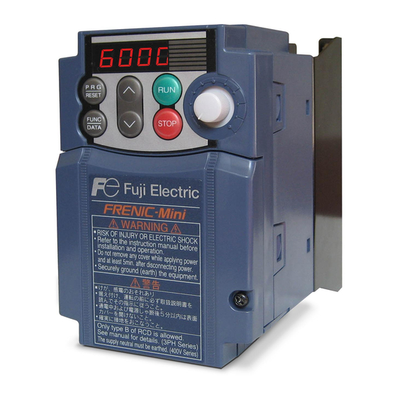
Fuji Electric FRENIC-mini Supplement To Instruction Manual
Three-phase 200 v series, three-phase 400 v series, single-phase 200 v series
Hide thumbs
Also See for FRENIC-mini:
- User manual (366 pages) ,
- Instruction manual (196 pages) ,
- Instruction manual (192 pages)
Advertisement
Table of Contents
Compact Inverter
Three-phase 200 V series: FRN0001 to 0020C2S-2U
Three-phase 400 V series: FRN0002 to 0011C2S-4U
Single-phase 200 V series: FRN0001 to 0012C2S-7U
Thank you for purchasing our FRENIC-Mini series of inverters.
This manual is a supplement to the FRENIC-Mini Instruction Manual (INR-SI47-1729-E),
•
contains descriptions complying with UL standard.
For other descriptions, refer to the original manual.
• Improper handling might result in incorrect operation, a short life, or even a failure of this
product as well as the motor.
• Deliver this manual to the end user of this product. Keep this manual in a safe place until this
product is discarded.
• For instructions on how to use an optional device, refer to the instruction and installation
manuals for that optional device.
Fuji Electric Co., Ltd.
Supplement to Instruction Manual
1
INR-SI47-1847-E
Advertisement
Table of Contents

Subscribe to Our Youtube Channel
Summary of Contents for Fuji Electric FRENIC-mini
- Page 1 Three-phase 400 V series: FRN0002 to 0011C2S-4U Single-phase 200 V series: FRN0001 to 0012C2S-7U Thank you for purchasing our FRENIC-Mini series of inverters. This manual is a supplement to the FRENIC-Mini Instruction Manual (INR-SI47-1729-E), • contains descriptions complying with UL standard.
-
Page 2: Chapter 2 Mounting And Wiring Of The Inverter
Chapter 2 MOUNTING AND WIRING OF THE INVERTER 2.3.5 Wiring for main circuit terminals and grounding terminals Inverter output terminals, U, V, W and grounding terminal ( G) 1) Connect the three wires of the three-phase motor to terminals U, V, and W, aligning phases each other. 2) Connect the grounding wire of terminals U, V, and W to the grounding terminal ( 3) If the cable from the inverter to the motor is very long, a high-frequency current may be generated by stray capacitance between the cables and result in an overcurrent trip of the inverter, an increase in leakage... - Page 3 11.5.2 Considerations when using FRENIC-Mini in systems to be certified by UL and cUL To use the FRENIC-Mini series of inverters as a part of UL Standards or CSA Standards (cUL certified) certified product, refer to the guidelines given below.
- Page 4 Conformity to UL standards and Canadian standards (cUL certification) If installed according to the guidelines given below, inverters marked with UL/cUL are considered as compliant with the UL and CSA (cUL certified) standards Integral solid state short circuit protection does not provide branch circuit protection. Branch circuit protection must be provided in accordance with the National Electrical Code and any additional local codes.
- Page 5 Conformity to UL standards and Canadian standards (cUL certification) (Continued) 5. Install UL certified fuses rated 600Vac between the power supply and the inverter, referring to the table below. Required torque Wire size Ib-in (N m) AWG or kcmil Power supply Inverter type Control circuit...
-
Page 6: Instruction Manual
In no event will Fuji Electric Co., Ltd. be liable for any direct or indirect damages resulting from the application of the information in this manual.


Need help?
Do you have a question about the FRENIC-mini and is the answer not in the manual?
Questions and answers