Table of Contents
Advertisement
Quick Links
High-Performance, Multi-Function Inverter
Thank you for purchasing our multifunction FRENIC-MEGA series of high-performance, multi-function inverters.
•
This product is designed to drive a three-phase motor under variable speed control. Read through this user's
manual and become familiar with the handling procedure for correct use.
•
Incorrect handling may hinder normal operation, or result in a shortening of the product life or failure.
•
Deliver this manual to the end user of this product.
•
Keep this manual in a safe place until this product is discarded.
•
For how to use an optional device, refer to the instruction and installation manuals for that optional device.
The English version of this document can be downloaded from the following site.
https://www.fujielectric.com/products/drive-download/
The Chinese version of this document can be downloaded from the following site.
https://www.fujielectric.com.cn/download_list.php
User's Manual
24A7-E-0162
Advertisement
Chapters
Table of Contents

Related Manuals for Fuji Electric FRENIC MEGA G2 Series


Summary of Contents for Fuji Electric FRENIC MEGA G2 Series
- Page 1 High-Performance, Multi-Function Inverter User’s Manual Thank you for purchasing our multifunction FRENIC-MEGA series of high-performance, multi-function inverters. • This product is designed to drive a three-phase motor under variable speed control. Read through this user's manual and become familiar with the handling procedure for correct use. •...
- Page 3 Every effort has been made to ensure the accuracy of the content of this manual, however, please contact your dealer or relevant Fuji Electric sales office at the end of this manual if there is anything that is unclear, or if any...
- Page 5 Preface Thank you for purchasing our “FRENIC-MEGA” series of high-performance, multi-function inverters. This product is designed to drive a three-phase motor under variable speed control. This manual provides all the information on the FRENIC-MEGA series of inverters including its operating procedure and selection of peripheral equipment.
- Page 6 How this manual is organized This manual is configured as follows. Chapter 1 BEFORE USE This chapter describes the items to checked before the use of the inverter. Chapter 2 INSTALLATION AND WIRING This chapter describes the important points in installing and wiring inverters. Chapter 2 OPERATION USING THE KEYPAD This chapter describes inverter keypad operation.
- Page 7 CONTENTS Chapter 1 BEFORE USE Acceptance Inspection (Nameplate and Inverter Type) ..............1-1 Product External Appearance ......................1-3 Precautions for Using Inverters ......................1-5 1.3.1 Usage environment ........................1-5 1.3.2 Storage environment ........................1-8 [ 1 ] Temporary storage ........................1-8 [ 2 ] Long-term storage ........................
- Page 8 [ 2 ] Settings under PID dancer control ..................3-12 3.3.7 Jogging operation ........................3-14 3.3.8 Switching between local and remote modes ................3-15 3.3.9 Changing the M/Shift key function ....................3-16 3.3.10 Display when keypad operation disabled (command source display) ........3-16 Programming Mode .........................
- Page 9 [ 2 ] Motor protection with thermistor ..................... 4-38 Setting function codes when switching from a conventional model ..........4-39 4.9.1 Switching from FRENIC-MEGA (G1S) ..................4-39 [ 1 ] Copying function codes using the keypad ................4-39 [ 2 ] Entering function codes directly from the keypad ..............
- Page 10 5.3.6 A, b, r codes (Motor 2 to 4 parameters) ..................5-261 5.3.7 b, r codes (Speed control 3 and 4 parameters) ................. 5-266 5.3.8 J codes (Applied functions) ....................... 5-267 [ 1 ] PID command with keypad (J02 = 0, factory default) ............5-268 [ 2 ] PID command by analog inputs (J02 = 1) ................
- Page 11 [ 25 ] lin Input phase loss ......................6-19 [ 26 ] lok Password protection ...................... 6-20 [ 27 ] lU Undervoltage ........................6-20 [ 28 ] nrb NTC wire break error ..................... 6-20 [ 29 ] 0Cn Instantaneous overcurrent ..................... 6-21 [ 30 ] 0H1 Cooling fin overheat .......................
- Page 12 [ 5 ] ] Display of parenthesis ....................6-42 [ 6 ] Data of function codes cannot be changed ................6-42 [ 7 ] Function code data are not changeable (change from link functions) ........6-43 [ 8 ] en.Off appears ........................6-43 [ 9 ] Other status display ........................
- Page 13 [ 6 ] PMSM drive ..........................8-17 FM Output Section ........................... 8-19 Chapter 9 COMMUNICATION FUNCTIONS Overview of RS-485 Communication ....................9-1 9.1.1 RS-485 common specifications ..................... 9-2 9.1.2 RS-485 communication terminal specifications ................9-3 [ 1 ] RS-485 COM port 1 (RJ-45 connector for keypad connection) specification ......9-3 [ 2 ] RS-485 COM port 2 (terminal block) specifications ..............
- Page 14 11.8.2 Overview of Braking Resistors (DB) and Braking Units............. 11-17 [ 1 ] Standard type ........................11-17 [ 2 ] 10%ED type ........................... 11-17 [ 3 ] Overview of braking unit ......................11-18 11.8.3 Specification ..........................11-19 11.8.4 External dimensions ........................11-22 11.9 High Power Factor Power Supply Regeneration PWM Converters (RHC Series) ......
- Page 15 11.23 Multi-function Keypad (TP-A2SW) ....................11-135 Chapter 12 SPECIFICATIONS 12.1 Standard Specifications 1 (Basic Type) ................... 12-1 12.1.1 Three-phase 200V series ......................12-1 12.1.2 Three-phase 400 V series ......................12-4 12.2 Standard Specifications 2 (Type with Built-in EMC Filter) ..............12-8 12.2.1 Three-phase 400V series ......................
- Page 16 Appendix F Permissible Current of Insulated Wires ..................26 Appendix G Conformity with Standards ...................... 29 Compliance with European Standards ( ) ................29 [ 1 ] Compliance with EMC standards ....................29 [ 2 ] Compliance with European Low Voltage Directive ..............34 Harmonic Component Regulations in EU ..................
- Page 17 ■ Safety precautions Be sure to read this User's Manual thoroughly prior to installation, wiring (connection), operation, maintenance, or inspection to ensure correct use of the product. Furthermore, ensure a thorough understanding of device knowledge, safety information, as well as all related precautions. Safety precautions contained in this User's Manual have been categorized as follows.
- Page 18 Wiring • If no zero-phase current (earth leakage current) detective device such as a ground-fault relay is installed in the upstream power supply line in order to avoid the entire power supply system's shutdown undesirable to factory operation, install a residual-current-operated protective device (RCD)/earth leakage circuit breaker (ELCB) individually to inverters to break the individual inverter power supply lines only.
- Page 19 Operation • Be sure to attach the inverter surface cover before turning the power ON. Do not remove the surface cover while the power is ON. • Do not operate the unit with wet hands. Failure to observe this could result in electric shock. •...
- Page 20 • The cooling fans and braking resistors become very hot. Do not touch. Failure to observe this could result in burns. • Mechanical holding is not possible with the inverter brake function. Failure to observe this could result in injury. •...
- Page 21 Maintenance and inspection, part replacement • Carry out inspection after waiting 5 minutes or longer for units of FRN0115G2S-2G/FRN0060G2□-4G or lower, or 10 minutes or longer for units of FRN0146G2S-2G/FRN0075G2□-4G or higher after turning OFF the power. Furthermore, ensure that the LED monitor and charge lamp are OFF, and use a device such as a tester to ensure that the DC intermediate circuit voltage across main circuit terminals P(+) and N(-) has dropped to a safe level (+25 VDC or less).
- Page 23 Chapter 1 BEFORE USE This chapter explains the items to be checked before the use of the inverter. Contents Acceptance Inspection (Nameplate and Inverter Type) ··················································· 1-1 Product External Appearance ··················································································· 1-3 Precautions for Using Inverters ················································································· 1-5 1.3.1 Usage environment ························································································ 1-5 1.3.2 Storage environment ·······················································································...
- Page 25 1.1 Acceptance Inspection (Nameplate and Inverter Type) Acceptance Inspection (Nameplate and Inverter Type) Unpack the package and check the following: The package contains both the inverter unit and instruction manual (Simplified Edition), and the product has suffered no damage (breakage, dents, parts that have fallen off) during transport. The rating plate is affixed to inverter at the location shown in Fig.
- Page 26 1.1 Acceptance Inspection (Nameplate and Inverter Type) There are two specifications of inverter, HHD and HND, and the specification is changed based on the load applied to the inverter. The respective specification is indicated on the nameplate. For details on the HHD and HND specifications, refer to Chapter 4 “4.4 Switching the Applicable Motor Rating (HHD/HND Specifications)”...
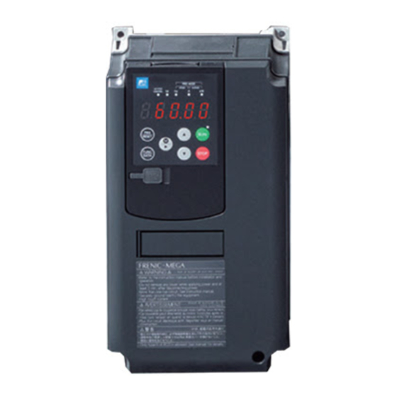
- Page 27 1.2 Product External Appearance Product External Appearance Overall external appearance Front cover Control circuit terminal block Cooling fan Keypad Front cover Main Nameplate Warning plate Main circuit Front cover terminal block mounting screw (a) FRN0005G2S-2G Front cover Control circuit Cooling fans terminal block Keypad Front cover...
- Page 28 1.2 Product External Appearance Warning plates and label (a) FRN0115G2S-2G or lower, (b) FRN0146G2S-2G or higher, FRN0060G2□-4G or lower FRN0075G2□-4G or higher Warning label Warning label Warning plate Fig. 1.2-2 Warning plates and label...
- Page 29 1.3 Precautions for Using Inverters Precautions for Using Inverters This section provides precautions in introducing inverters, e.g. precautions for installation environment, power supply lines, wiring, and connection to peripheral equipment. Be sure to observe those precautions. 1.3.1 Usage environment Install FRENIC-MEGA in an environment that satisfies the operating environment requirements listed in Table 1.3- Table 1.3-1 Operating environment Item Specifications...
- Page 30 1.3 Precautions for Using Inverters (Note 3) If the inverter is used in an environment which exceeds 50 °C, output current derating will be necessary. Output current derating factor *1: This applies to FRN0008G2S-2G, FRN0023G2□-4G, and FRN0045G2□-4G...
- Page 31 1.3 Precautions for Using Inverters Fuji Electric strongly recommends installing inverters in a panel for safety reasons, in particular, when installing the ones whose enclosure rating is IP00. When installing the inverter in a place out of the specified environmental requirements, it is necessary to derate the inverter or consider the panel engineering design suitable for the special environment or the panel installation location.
- Page 32 1.3 Precautions for Using Inverters 1.3.2 Storage environment The storage environment in which the inverter should be stored after purchase differs from the usage environment. Store the FRENIC-MEGA in an environment that satisfies the requirements listed below. [ 1 ] Temporary storage Table 1.3-3 Storage and transport environments Item...
- Page 33 1.3 Precautions for Using Inverters 1.3.3 Precautions for connection of peripheral equipment [ 1 ] Phase-advancing capacitors for power factor correction Do not mount a phase-advancing capacitor for power factor correction in the inverter's input (primary) or output (secondary) circuit. Mounting it in the input (primary) circuit takes no effect. To correct the inverter power factor, use a DC reactor (DCR) (option).
- Page 34 1.3 Precautions for Using Inverters [ 4 ] PWM converter for correcting the inverter input power factor Using a PWM converter (High power-factor, regenerative PWM converter, RHC series) corrects the inverter power factor up to nearly “1.” When combining an inverter with a PWM converter, disable the main power down detection by setting the function code H72 (main power detection) to “0”...
- Page 35 1.3 Precautions for Using Inverters 1.3.4 Noise reduction If noise generated from the inverter affects other devices, or that generated from peripheral equipment causes the inverter to malfunction, follow the basic measures outlined below. If noise generated from the inverter affects the other devices through power wires or grounding wires: - Isolate the grounding terminals of the inverter from those of the other devices.
- Page 37 Chapter 2 INSTALLATION AND WIRING This chapter describes the important points in installing and wiring inverters. Contents Installation ············································································································ 2-1 Wiring ················································································································· 2-4 2.2.1 Basic connection diagrams ··············································································· 2-4 2.2.2 Removal and attachment of the front cover and wiring guide ··································· 2-6 2.2.3 Wiring precautions ··························································································...
- Page 39 2.1 Installation Installation (1) Installation environment Please install FRENIC-MEGA in locations which meet the requirements specified in Chapter 1 “1.3.1 Operating environment”. (2) Installation surface Please install the inverter on noncombustibles such as metal. Also, do not mount it upside down or horizontally. Install on noncombustibles such as metal.
- Page 40 2.1 Installation ■ Installation with external cooling The external cooling installation reduces the generated heat inside the panel by dissipating approximately 70% of the total heat generated (total heat loss) by mounting the cooling fins protruding outside the equipment or cabinet. The external cooling unit body has a protective construction of IP55.
- Page 41 2.1 Installation If installing a FRN0146G2S-2G / FRN0075G2□-4G or higher inverter with external cooling, change the mounting position of the upper and lower mounting bases using the following procedure. (See Fig. 2. 1-3 below.) The screw types and number of screws used will differ depending on the inverter type. Please check the following table.
- Page 42 2.2 Wiring Wiring 2.2.1 Basic connection diagrams Braking resistor (CM) P P(+)R DB (THR) P(+) N(-) Braking resistor (DBR) Bra king un it (BU) P(+) N(-) (CM) DC reactor (THR) (DCR) Main circuit Circuit breaker (MCCB) or earth Thermal leakage circuit P(+) Magnetic N(-)
- Page 43 2.2 Wiring (*1) Install the molded case circuit breaker (MCCB) or earth leakage circuit breaker (ELCB) (with overcurrent protection function) recommended for each inverter on the inverter input side (primary side) to protect wiring. Do not use a circuit breaker that exceeds the recommended rated current. (*2) An MCCB or ELCB is also used if isolating the inverter from the power supply, and therefore the magnetic contactor (MC) recommended for each inverter should be installed if required.
- Page 44 2.2 Wiring Carry out wiring work in the following order (The descriptions assume that the inverter has already been installed). 2.2.2 Removal and attachment of the front cover and wiring guide If using the RS-485 communication cable for such purposes as remotely operating the keypad, always remove the RS-485 communication cable from the RJ-45 connector before removing the front cover.
- Page 45 2.2 Wiring 2.2.3 Wiring precautions Pay attention to the following items when carrying out wiring. Confirm that the supply voltage is within the input voltage range described on the rating plate. Always connect the power lines to the inverter main power input terminals L1/R, L2/S, and L3/T (three-phase). (The inverter will be damaged when power is applied if the power lines are connected to the wrong terminals.) Be sure to connect a ground wire in order to prevent accidents such as electric shock or fire, and to reduce noise.
- Page 46 2.2 Wiring ■ Handling the wiring guide When wiring the main circuit on FRN0059G2S-2G to FRN0115G2S-2G / FRN0031G2□-4G to FRN0060G2□-4G inverters, the wiring space may become insufficient when routing the main circuit wires, depending on the wire material used. In these cases, the relevant cut-off sections (see figure below) can be removed using a pair of nippers to secure routing space.
- Page 47 For motors with encoders, the wiring length between the inverter and motor should be below 100 m (328ft). The restriction comes from the encoder specifications. For distances beyond 100 m (328ft), insulation converters should be used. Please contact Fuji Electric when operating with wiring lengths beyond the upper limit.
- Page 48 2.2 Wiring Connect to the power supply via a molded case circuit breaker or earth leakage circuit breaker (with overcurrent protection function) for each inverter. Use the recommended molded case circuit breaker or earth leakage circuit breaker, and do not use circuit breakers that exceed the recommended rated current.
- Page 49 2.2 Wiring 2.2.5 Main circuit terminals [ 1 ] Screw specifications and recommended wire size (main circuit terminals) The specifications for the screws used in the main circuit wiring and the wire sizes are shown below. Exercise caution as the terminal position varies depending on inverter capacity. In the diagram in "[ 2 ] Terminal layout diagrams (main circuit terminals)”, the two ground terminals [*G] are not differentiated for the input side (primary side) and the output side (secondary side).
- Page 50 2.2 Wiring [ 2 ] Terminal layout diagrams (main circuit terminals) The dimensions for each terminal indicate the “dimensions between walls” as shown in the diagram on the left. Figure A Figure B Figure C Charging lamp Charging lamp Charging lamp Terminal block width Terminal block width: 6.6 - R0, T0: 6.6...
- Page 51 2.2 Wiring The following terminals will have high voltage when power is ON. Main circuit: L1/R, L2/S, L3/T, P1, P(+), N(-), DB, U, V, W, R0, T0, AUX-contact (30A, 30B, 30C, Y5A, Y5C) Insulation level Main circuit - casing : Basic insulation (overvoltage category III, pollution degree 2) Main circuit - control circuit : Reinforced insulation (overvoltage category III, pollution degree 2) Contact output - control circuit...
- Page 52 2.2 Wiring Panel internal temperature of 50 C (122 °F) or lower Table 2.2-3 Wire size (main power supply input and inverter output) HHD specification: High, Heavy Duty applications HND specification: High, Normal Duty applications Recommended wire size (mm Inverter type Main power supply input [L1/R, L2/S, L3/T] Inverter output [U, V, W] With DC reactor (DCR)
- Page 53 2.2 Wiring Table 2.2-3 Wire size (main power supply input and inverter output) (cont.) HHD specification: High, Heavy Duty applications HND specification: High, Normal Duty applications Recommended wire size (mm Inverter type Main power supply input [L1/R, L2/S, L3/T] Inverter output [U, V, W] With DC reactor (DCR) Without DC reactor (DCR) HHD specification...
- Page 54 2.2 Wiring Table 2.2-3 Wire size (for DC reactor connection, for braking resistor connection, and for inverter grounding) (cont.) HHD specification: High, Heavy Duty applications HND specification: High, Normal Duty applications Recommended wire size (mm For inverter Inverter type For braking resistor connection [P(+), DB] (Note 2) For DC reactor connection grounding [P1, P(+)]...
- Page 55 2.2 Wiring Table 2.2-3 Wire size (for DC reactor connection, for braking resistor connection, and for inverter grounding) (cont.) HHD specification: High, Heavy Duty applications HND specification: High, Normal Duty applications Recommended wire size (mm For inverter For braking resistor connection [P(+), DB] (Note 3) Inverter type For DC reactor connection grounding...
- Page 56 2.2 Wiring Panel internal temperature of 40 C (104 °F) or lower Table 2.2-4 Wire size (main power supply input and inverter output) HHD specification: High, Heavy Duty applications HND specification: High, Normal Duty applications Recommended wire size (mm Inverter type Main power supply input [L1/R, L2/S, L3/T] Inverter output [U, V, W] With DC reactor (DCR)
- Page 57 2.2 Wiring Table 2.2-4 Wire size (main power supply input and inverter output) (cont.) HHD specification: High, Heavy Duty applications HND specification: High, Normal Duty applications Recommended wire size (mm Inverter type Main power supply input [L1/R, L2/S, L3/T] Inverter output [U, V, W] With DC reactor (DCR) Without DC reactor (DCR) HHD specification...
- Page 58 2.2 Wiring Table 2.2-4 Wire size (for DC reactor connection, for braking resistor connection, and for inverter grounding) (cont.) HHD specification: High, Heavy Duty applications HND specification: High, Normal Duty applications Recommended wire size (mm For inverter Inverter type For braking resistor connection [P(+), DB] (Note 2) For DC reactor connection grounding [P1, P(+)]...
- Page 59 2.2 Wiring Table 2.2-4 Wire size (for DC reactor connection, for braking resistor connection, and for inverter grounding) (cont.) HHD specification: High, Heavy Duty applications HND specification: High, Normal Duty applications Recommended wire size (mm For inverter For braking resistor connection [P(+), DB] (Note 3) Inverter type For DC reactor connection grounding...
- Page 60 2.2 Wiring [ 4 ] Terminal function description (main circuit terminals) Classifi Terminal symbol Terminal command Detailed specifications cation L1/R, L2/S, L3/T Main power supply input Connect a three-phase power supply. U, V, W Inverter output Terminals to connect three-phase motors. Connect a DC reactor (DCR) (option).
- Page 61 2.2 Wiring (1) Inverter grounding terminal *G Be sure to ground grounding terminals to ensure safety, and as a noise countermeasure. In order to prevent accidents such as an electric shock or fire, users are obligated by the Electrical Equipment Technical Standards to carry out grounding work for the metal frames of electrical equipment.
- Page 62 2.2 Wiring (4) Braking resistor connection terminals P(+), DB Table 2.2-5 Type of Inverter Braking Built-in Additional connected Work procedure transistor braking devices (option) FRN□□□□G2S-2G FRN□□□□G2□-4G resistor (Capacity kW) (Capacity kW) 0003 to 0046 0002 to 0023 Breaking resistor Perform 1), 2), 3), Built-in Built-in (higher capacity)
- Page 63 The direct current intermediate circuit of other inverters and PWM converters can be connected. Contact Fuji Electric if using terminals P(+) and N(-) for DC bus bar connection. (6) Main power supply input terminals L1/R, L2/S, and L3/T (three-phase input) Connect a three-phase power supply.
- Page 64 2.2 Wiring (7) Control power auxiliary input terminals R0, T0 (FRN0008G2S-2G / FRN0004G2□-4G or higher) The inverter can be run even without inputting the power supply to the control power auxiliary input terminals. However, control power will also be lost by cutting off the inverter main power supply, and therefore all inverter output signals will stop, and the keypad will no longer display.
- Page 65 2.2 Wiring 2.2.6 Control circuit terminals (common to all models) [ 1 ] Screw specifications and recommended wire size (control circuit terminals) The specifications for the screws used in the control circuit wiring and the wire sizes are shown below. The control circuit terminal block is common, regardless of the inverter capacity.
- Page 66 2.2 Wiring [ 3 ] Control circuit wiring precautions ■ FRN0346GS-2G, FRN0432G2S-2G, FRN0325G2□-4G to FRN1386G2□-4G Run the wiring along the plate on the left side of the inverter as shown in Fig. 2.2-13. Secure the wiring to wire holders with cable ties (INSULOK, etc.) Use cable ties with width of no greater than 3.8 mm (0.15 in), and thickness of no greater than 1.5 mm (0.06 in).
- Page 67 2.2 Wiring [ 4 ] Description of terminal functions (control circuit terminals) A description of control circuit terminal functions is shown in Table 2.2-9. The control circuit terminal connection method differs based on function code settings to suit the purpose for which the inverter is used. Wire appropriately to minimize the effect of noise from main circuit wiring.
- Page 68 2.2 Wiring Table 2.2-9 Description of control circuit terminal functions (cont.) Terminal Terminal Function description symbol command [C1] Analog (1) Frequency is set up according to the external analog current input command value. setting ∙ 4 to 20 mA DC/0 to 100(%), 0 to 20 mA DC/0 to 100(%) (normal operation) current input ∙...
- Page 69 2.2 Wiring Table 2.2-9 Description of control circuit terminal functions (cont.) Terminal Terminal Function description symbol command [V2] PTC/NTC (1) PTC (Positive Temperature Coefficient)/NTC (Negative Temperature Coefficient) thermistor thermistors for motor protection can be connected. SW5 (see “2.2.7 Switching switches”) input on the PCB must be switched to the PTC/NTC side.
- Page 70 2.2 Wiring Digital input terminals Table 2.2-10 Description of control circuit terminal functions Terminal Terminal Function description symbol command [X1] Digital (1) Various signals (coast to stop command, external alarm, multi-speed selection, etc.) can be set with function codes E01 to E09, E98, E99. Refer to Chapter 5 "FUNCTION input 1 CODES"...
- Page 71 2.2 Wiring [PLC] Programmable (1) Connect the output signal power supply for the programmable controller. controller signal (Rated voltage +24 VDC (power supply voltage fluctuation range: 20 to +27 VDC), power supply maximum 100 mA) (2) The terminal can also be used as the power supply for loads connected to transistor outputs.
- Page 72 SOURCE side. Caution: Use relay contacts which do not have contact failures (high contact reliability). (Recommended product: Fuji Electric control relay, model: HH54PW) (a) If switch at SINK side (b) If switch at SOURCE side Example of circuit configuration using relay contacts Fig.
- Page 73 2.2 Wiring ■ When inputting pulse train with terminals [X6] and [X7] If connecting to an open collector output pulse generator, it may not be possible to correctly recognize input pulses due to the stray capacitance of the wiring. In response to this, if the changeover switch is set to the SINK side, connect a pull-up resistor between the open collector output signals (terminals [X6], [X7]) and the power supply (terminal [PLC]), and if the changeover switch is set to the SOURCE side, connect a pull-down resistor between the open collector output signals (terminals [X6], [X7]) and the digital common (terminal...
- Page 74 2.2 Wiring Analog output, pulse output, transistor output, contact output terminals Table 2.2-12 Description of control circuit terminal functions Terminal Terminal Function description symbol command [FM1] Analog These terminals output analog DC voltage of 0 to ±10 VDC, and analog DC current of 4 to 20 monitor mA DC or 0 to 20 mA DC monitor signals.
- Page 75 2.2 Wiring Table 2.2-12 Description of control circuit terminal functions (cont.) Terminal Terminal Function description symbol command [Y1] Transistor (1) Various signals (running signal, frequency reached signal, overload forecast signal, etc.) set output 1 up by function code E20 to E24 can be output. Refer to "Chapter 5 FUNCTION CODES" for details.
- Page 76 2.2 Wiring Table 2.2-12 Description of control circuit terminal functions (cont.) Terminal Terminal Function description symbol command ■ If connecting a programmable controller to terminals [Y1] to [Y4] An example of a circuit configuration in which inverter transistor output is connected to a programmable controller is shown in Fig.
- Page 77 2.2 Wiring RS-485 communication connector Table 2.2-14 Description of control circuit terminal functions Terminal Terminal Function description symbol command RJ-45 RS-485 (1) This is used as a connector for connecting the keypad. The keypad power is supplied from connector communicatio the inverter via an extension cable for remote operation.
- Page 78 2.2 Wiring 2.2.7 Switching switches Switch all switches after first waiting for at least 5 minutes for FRN0115G2S-2G / FRN0060G2□-4G or lower, or 10 minutes for FRN0146G2S-2G / FRN0075G2□-4G or higher after turning off the power, ensuring that the LED monitor and charge lamp are off, and using a device such as a tester to ensure that the DC intermediate circuit voltage across main circuit terminals P(+) - N(-) has dropped to a safe level (+25 VDC or less).
- Page 79 2.2 Wiring <Terminal [V2] function changeover switch> The switch can be set to either analog setting voltage input or PTC/NTC thermistor input as the terminal [V2] function. When operating this switch, also change function code H26. Table 2.2-17 H26 data Input type Analog setting voltage input V2 side...
- Page 80 2.2 Wiring The switch locations on the control PCB are shown below. Fig. 2.2-25 Switch positions Table 2.2-21 Switch changeover and factory default settings SINK Variable range SOURCE PTC/NTC SINK Factory default The factory default setting for SW1 of FRN-G2E-4G is “SOURCE”. To change the switch settings, use a tool with fine tip (tweezers, etc.), and be careful not to touch any other electronic components.
- Page 81 2.3 Mounting and Removing the Keypad Mounting and Removing the Keypad The keypad can be removed from the inverter unit, and installed on the panel, or used for remote manual operation. RJ-45 connector Cabinet Keypad mounting screws Inverter main body Keypad (rear side) Extension cable for remote operation...
- Page 83 Chapter 3 OPERATION USING THE KEYPAD This chapter describes inverter keypad operation. Contents Name and Function of Each Keypad Part ···································································· 3-1 Overview of Operation Modes ·················································································· 3-3 Running Mode ······································································································ 3-5 3.3.1 Operating state monitor ··················································································· 3-5 3.3.2 Status display ································································································ 3-7 3.3.3 Monitoring warnings ························································································...
- Page 85 3.1 Name and Function of Each Keypad Part Name and Function of Each Keypad Part The keypad allows you to run and stop the inverter, display various data, configure function code data, monitor I/O signal states, and display maintenance information and alarm information. 7-segment LED monitor LED indicators UP key...
- Page 86 3.1 Name and Function of Each Keypad Part Item Display and keys Function overview Lights when running with a run command entered by the key, by terminal command (green) “FWD” or “REV”, or through the communications link. Lights up when the keypad key is valid as a run command.
- Page 87 3.2 Overview of Operation Modes Overview of Operation Modes FRENIC-MEGA is equipped with the following three operation modes. Table 3.2-1 Operation modes Operation mode Description When powered ON, the inverter automatically enters this mode. This mode allows you to specify the reference frequency, PID command value and etc., and run/stop the motor with the keys.
- Page 88 3.2 Overview of Operation Modes Simultaneous keying Simultaneous keying means pressing two keys at the same time. The simultaneous keying operation is expressed by a “+” letter between the keys throughout this manual. For example, the expression " keys” stands for pressing the key with the key held down.
- Page 89 3.3 Running Mode Running Mode 3.3.1 Operating state monitor In running mode, the items in Table 3.3-1 below can be monitored. The monitor items set with function code E43 are displayed immediately after turning the power on. Press the key to switch between monitor items. Power ON Power Speed monitor...
- Page 90 3.3 Running Mode Table 3.3-1 Monitor items (cont.) Monitor Monitor item LED indication Unit Meaning of displayed value Data for E43 example Motor output *3 9.85 〇Hz 〇A ●kW Motor output (kW) Load factor of the motor in % as the rated 〇Hz 〇A 〇kW Load factor *4 output being at 100%...
- Page 91 3.3 Running Mode When the LED monitor displays a PID command or its output amount, the dot (decimal point) attached to the lowest digit of the 7-segment letter blinks. When the LED monitor displays a PID feedback amount, the dot (decimal point) attached to the lowest digit of the 7-segment letter lights.
- Page 92 3.3 Running Mode 3.3.3 Monitoring warnings The FRENIC-MEGA identifies abnormal states in two categories-- Alarm and Warning. If a warning occurs, the running status monitor (frequency display, etc.) and warning code display alternately on the LED monitor. Which abnormal states are categorized as a warning (“Warning” object) should be defined with function codes H81, H82, and H83 beforehand.
- Page 93 3.3 Running Mode 3.3.4 Running or stopping the motor with the keypad By factory default, pressing the key starts running the motor in the forward direction and pressing the decelerates the motor to stop. The key is enabled only in Running mode. When the inverter is running, the RUN LED lights.
- Page 94 3.3 Running Mode • In order to perform setting such as reference frequency, press once and when the least significant digit flashes, push down the key, and then, the flashing digit will move. Therefore, it is possible to change the large numerical number easily. •...
- Page 95 3.3 Running Mode Table 3.3-4 PID process command manually set with key and requirements PID control PID control PID control multistage (Remote LED monitor With (Mode command command SV) selection) J01 PID-SS1, PID-SS2 PID process command with keypad 1 or 2 Other than 0 ON or OFF Other than 0...
- Page 96 3.3 Running Mode [ 2 ] Settings under PID dancer control To enable the PID dancer control, you need to set the J01 data to “3.” Under the PID control, the items that can be specified or checked with keys are different from those under regular frequency control, depending upon the current LED monitor setting.
- Page 97 3.3 Running Mode Setting up the primary frequency command with keys under PID dancer control When function code F01 is set to “0” ( keys on keypad) and frequency setting 1 is selected as a main setting (when disabling the frequency setting command via communications link, multistep frequency command, and PID control), switching the LED monitor to the speed monitor in Running mode enables you to modify the main setting with the keys.
- Page 98 3.3 Running Mode 3.3.7 Jogging operation This section provides the procedure for jogging the motor. Make the inverter ready to jog by following the steps below. The LED monitor should display JoG. ∙ Set the operation mode to Running mode. (See “3.2 Overview of Operation Modes”.) ∙...
- Page 99 3.3 Running Mode 3.3.8 Switching between local and remote modes When performing normal operation, the motor runs in the remote mode with the operation method set at the inverter, and when performing maintenance, it is possible to switch to the local mode used for performing operation with the keypad.
- Page 100 3.3 Running Mode 3.3.9 Changing the M/Shift key function When in Running mode, various functions can be assigned to the M/Shift key in the same way as digital input terminals based on the function code E70 setting. The switching between remote and local modes described in the previous section is one of these functions.
- Page 101 3.4 Programming Mode Programming Mode The Programming mode provides you with the following functions--setting and checking function code data, monitoring maintenance information and checking input/output (I/O) signal status. The functions can be easily selected with the menu-driven system. Table 3.4-1 below lists menus available in Programming mode. The leftmost digit (numerals) of each letter string on the LED monitor indicates the corresponding menu number and the remaining digits indicate the menu contents.
- Page 102 3.4 Programming Mode 3.4.1 Setting function codes “Data Setting: 1.f__ to 1.k__” Menu number 1 “Data Setting” (1.f__ through 1.K__) in Programming mode allows you to configure all function codes. The Fig. 3.4-1 shows “Data Setting” menu transition and function code data change procedure. Programming mode Function code list Function code data...
- Page 103 3.4 Programming Mode When changing function code data, pressing the key once blinks the least significant digit. After that, each time the key is pressed, the cursor moves to the next higher digit where data can be changed. This cursor movement allows you to easily move the cursor to the desired digit and change the data in higher digits.
- Page 104 3.4 Programming Mode 3.4.2 Checking changed function codes “Data Checking: 2.rep” Changed function codes can be checked at “Data Checking: 2.rep” in menu number 2 of Programming mode. Only the function codes whose data has been changed from the factory defaults are displayed on the LED monitor. You can refer to the function code data and change it again if necessary.
- Page 105 3.4 Programming Mode 3.4.3 Monitoring the running status “Drive Monitoring: ope” Menu number 3 “Drive Monitoring: 3.ope” is used to monitor the running status during maintenance and test running. The monitor number and symbol are displayed alternately every 1 second. Table 3.4-2 “Drive Monitoring”...
- Page 106 3.4 Programming Mode Table 3.4-2 “Drive Monitoring” display items (cont.) Monitor Symbol Item Unit Description When this setting is 100%, the LED monitor shows 1.00 time of the value to be displayed. Ratio setting 3_14 ratio If no ratio setting is selected, “-----” appears.
- Page 107 3.4 Programming Mode Displaying running status (3_07) and running status 2 (3_23) ■ To display the running status and running status 2 in hexadecimal format, each state has been assigned to bits 0 to 15 as listed in Table 3.4-3 and Table 3.4-4 respectively. Table 3.4-5 shows the relationship between each of the status assignments and the LED monitor display.
- Page 108 3.4 Programming Mode Table 3.4-4 Running status 2 (3_23) bit assignment Symbol Content Symbol Content Speed limiting (under torque control) (Not used) Drive motor type Motor selection 0000: induction motor Motor 1 1000: synchronous motor Motor 2 Motor 3 Motor 4 Control method 0000: V/f control without slip compensation inactive...
- Page 109 3.4 Programming Mode Hexadecimal expression ■ A 4-bit binary number can be expressed in hexadecimal format (hexadecimal digit). The Table 3.4-7 below shows the correspondence between the two notations. Table 3.4-7 Binary and hexadecimal conversion Binary Hexadecimal Binary Hexadecimal 3.4.4 Checking I/O signal status “I/O Checking: 4.i_o”...
- Page 110 3.4 Programming Mode Basic key operation Turn the inverter ON. It automatically enters Running mode in which you press the key to switch Operation (1) to Programming mode. The function selection menu appears. Use the keys to select “I/O Checking” ( 4.i_o ). Operation (2) Press the key to skip in menu number units.
- Page 111 3.4 Programming Mode Table 3.4-8 “I/O Checking” items Monitor Symbol Item Unit Description Displays the ON/OFF state of the digital I/O I/O signals on the control terminals. Refer to “Displaying control I/O 4_00 dio.t circuit terminals signal terminals” on the next page for details. Displays the ON/OFF state of the digital I/O terminals that received a command via RS-485 I/O signals on the control...
- Page 112 3.4 Programming Mode Monitor Symbol Item Unit Description Displays the input voltage on terminal [32] on Input voltage on terminal the analog interface card (AIO option) in volts 4_20 32-in [32] (V). Displays the input current on terminal [C2] on Input current on terminal the analog interface card (AIO option) in 4_21...
- Page 113 3.4 Programming Mode Displaying control I/O signal terminals ■ The status of control I/O signal terminals can be displayed in two ways: with ON/OFF of each LED segment and in hexadecimal. Displaying the I/O signal status with ON/OFF of each LED segment ⚫...
- Page 114 3.4 Programming Mode Table 3.4-10 Display of I/O signal status in hexadecimal notation (example) LED No. LED 4 LED 3 LED 2 LED 1 Input terminal (RST) * (XR) * (XF) * EN2 EN1 X9 X1 REV FWD Output 30A/ terminal Binary LED5 LED4 LED3 LED2 LED1...
- Page 115 3.4 Programming Mode 3.4.5 Reading maintenance information “Maintenance Information: 5.CHE” Menu number 5 “Maintenance Information: 5.CHE” contains information necessary for performing maintenance on the inverter. The menu transition in “Maintenance Information” is same as that in Menu #3 “Drive Monitoring.” (Refer to Section 3.4.3 .) The monitor number and symbol are displayed alternately every 1 second.
- Page 116 3.4 Programming Mode Table 3.4-12 “Maintenance Information” display items (cont.) Monitor Symbol Item Displayed content Displays the content of the cumulative run time counter of the electrolytic capacitors on the printed circuit boards, which is Cumulative run calculated by multiplying the cumulative run time count by the time of electrolytic coefficient based on the surrounding temperature condition.
- Page 117 3.4 Programming Mode Table 3.4-12 “Maintenance Information” display items (cont.) Monitor Symbol Item Displayed content Keypad ROM Displays the keypad ROM version as a 4-digit code. 5_16 kEyPd version Displays the total number of errors that have occurred in RS- Number of RS-485 485 communication (COM port 2, connection to terminal communications...
- Page 118 3.4 Programming Mode Table 3.4-12 “Maintenance Information” display items (cont.) Monitor Symbol Item Displayed content Displays the content of the cumulative power-ON time counter Cumulative run of motor 3. 5_29 tM.M3 time for motor 3 The display method is the same as for 5_23 above. Displays the content of the cumulative power-ON time counter Cumulative run of motor 4.
- Page 119 3.4 Programming Mode Table 3.4-12 “Maintenance Information” display items (cont.) Monitor Symbol Item Displayed content Displays the type of option installed in the A-Port. Option A type 5_47 oPA.id See Table 3.4-13 for the display content. Displays the type of option installed in the B-Port. Option B type 5_48 oPb.id...
- Page 120 3.4 Programming Mode Table 3.4-13 Option type display list Displayed content Option type Not connected ----- OPC-PG OPC-PG2 PG2.3 OPC-PMPG2 / OPC-PG22 PMPG OPC-DI OPC-DO OPC-AIO OPC-PDP2 OPC-DEV OPC-COP2 OPC-CCL OPC-TL OPC-SX OPC-ETM 3-36...
- Page 121 3.4 Programming Mode 3.4.6 Reading alarm information “Alarm Information: 6.al” Menu number 6 “Alarm Information: 6.al” shows the causes of the past 4 alarms with an alarm code. Further, it is also possible to display alarm information that indicates the status of the inverter when the alarm occurred. Fig. 3.4-3 lists “...
- Page 122 3.4 Programming Mode Table 3.4-14 “Alarm Information” display content Monitor Symbol Displayed content Description Output frequency before slip compensation when alarm Output frequency 6_00 Fout1 occurred Output current when alarm occurred. Output current 6_01 iout Unit: A (amperes) Output voltage when alarm occurred Output voltage 6_02 Vout...
- Page 123 3.4 Programming Mode Table 3.4-14 “Alarm Information” display content (cont.) Monitor Symbol Displayed content Description Terminal I/O signal status (displayed 6_12 with ON/OFF of LED segments) Refer to “Table 3.4-9 Display of I/O signal status with ON/OFF Terminal input of each LED segment” and “Table 3.4-10 Display of I/O signal signal status status in hexadecimal notation (example)”...
- Page 124 3.4 Programming Mode Table 3.4-15 Running Status 3 (6_24) bit assignment Symbol Content Symbol Content Always “0.” “1” when the fan is in operation. 1 when keypad operation being “1” when current 2 is detected. performed “1” when a motor overload early “1”...
- Page 125 3.4 Programming Mode 3.4.7 Copying data “Data Copying: 7.Cpy” Data copying is used when reading function code data from the inverter and saving it in the TP-E2 keypad or in the multifunction keypad (TP-A2SW), when writing function code data to another inverter, or when comparing function code data saved to the keypad with function code data set in the inverter.
- Page 126 3.4 Programming Mode Basic key operation Operation (1) Turn the inverter ON. It automatically enters Running mode in which you press the key to switch to Programming mode. The function selection menu appears. Operation (2) Use the keys to display “Data Copying” ( 7.Cpy ). Press the key to skip in menu number units.
- Page 127 3.4 Programming Mode Table 3.4-17 List of data copying functions (cont.) Function Description indication Enable Data Enables the protection of data stored in the keypad memory. ProT protection Data cannot be read or erased from the keypad. Data writing, verification, and inverter operating information reading are possible. Upon pressing the key the inverter immediately displays “...
- Page 128 3.4 Programming Mode The following are restrictions and special notes concerning “Data Copying.” If unable to copy ■ Check whether the “err” or “diff” display is blinking. When the “err” display is blinking (write error), the following causes are conceivable. ∙...
- Page 129 3.4 Programming Mode 3.4.8 Setting “Favorites” function code data “Favorites: 0.fnC” Menu number 0 “Favorites” in Programming mode allows you to display only those function codes in “Favorites”, and make changes to function code data. There is no limit to the number of function code data items that can be registered.
- Page 130 3.5 Alarm Mode Alarm Mode If an abnormal condition arises, the protective function is invoked and issues an alarm, then the inverter automatically enters Alarm mode. At the same time, an alarm code appears on the LED monitor. 3.5.1 Releasing the alarm and switching to running mode Remove the cause of the alarm and press the key to release the alarm and return to Running mode.
- Page 131 3.6 USB Port USB Port There is a USB cable connection port (miniB) on the front of the keypad. To connect the USB cable, open the connection port cover and connect the cable as shown below. USB connection port cover Connect the inverter directly to a PC with the USB cable.
- Page 133 Chapter 4 TEST RUN PROCEDURE This chapter describes basic settings required for making a test run. Contents Test Run Procedure Flowchart ·················································································· 4-1 Checking Prior to Powering On ················································································· 4-2 Powering ON and Checking ····················································································· 4-3 Destination setting ································································································· 4-4 Switching the Applicable Motor Rating (HHD/HND Specifications) ····································...
-
Page 134: Table Of Contents
[ 2 ] Motor protection with thermistor ········································································ 4-38 Setting function codes when switching from a conventional model ··································· 4-39 4.9.1 Switching from FRENIC-MEGA (G1S) ······························································· 4-39 [ 1 ] Copying function codes using the keypad ··························································· 4-39 [ 2 ] Entering function codes directly from the keypad ··················································... - Page 135 4.1 Test Run Procedure Flowchart Test Run Procedure Flowchart Make a test run of the motor using the flowchart given below. This chapter describes the test run procedure with motor 1 dedicated function codes that are marked with an asterisk (*). When motor 2 to 4 is used, it is necessary to convert to the corresponding function codes.
- Page 136 4.2 Checking Prior to Powering On Checking Prior to Powering On Check the following before powering on the inverter. Check that the wiring is correct. Especially check the wiring to the inverter input terminals (L1/R, L2/S, L3/T) and output terminals (U, V, and W).
- Page 137 4.3 Powering ON and Checking Powering ON and Checking • Be sure to attach the surface cover before turning the power on. Do not remove the cover while the power is • Do not operate the unit with wet hands. Failure to observe this could result in electric shock.
- Page 138 4.4 Destination setting Destination setting For inverter type FRN****G2■-G (Global Model), the destination must be set first after the initial power supply. Without setting the destination, the function code cannot be changed. The inverter cannot be operated either. By setting the destination, basic function codes such as rated voltage, rated frequency, etc. are initialized to general values in each region (Table 4.4-1).
- Page 139 4.4 Destination setting RES ET RES ET RES ET For Japan For Asia For China For EU For Americas For East Asia LED Monitor Figure 4.4-1 Destination setting status transition chart...
- Page 140 4.5 Switching the Applicable Motor Rating (HHD/HND Specifications) Switching the Applicable Motor Rating (HHD/HND Specifications) By switching from the factory default HHD specification to the HND specification on three-phase 200V series and three-phase 400V series inverters, they can be used with a motor reference rated current of one to two ranks higher.
- Page 141 4.6 Selecting the Motor Control Method Selecting the Motor Control Method FRENIC-MEGA supports the following motor control methods. Refer to “4.7 Performance Comparison for Drive Controls (Summary)” for details on the features of each control method. Table 4.6-1 F42* Applicable Drive control Drive control...
- Page 142 4.6 Selecting the Motor Control Method 4.6.3 Dynamic torque vector control (induction motors) To get the maximal torque out of a motor, this control calculates the motor torque matched to the load applied and uses it to optimize the voltage and current vector output. When the vector control without speed sensor (dynamic torque vector) is selected, automatically auto torque boost and slip compensation become enabled.
- Page 143 4.6 Selecting the Motor Control Method 4.6.7 Vector control with sensor (induction motors) With this control, a PG interface card (option) must be installed. The inverter detects the motor’s rotational position and speed based on PG feedback signals from the motor PG, and uses them to control speed. It also breaks down the motor current into its exciting current and torque current components, and controls each of the components as vectors.
- Page 144 Sensorless vector control offers a wide speed control range, and highly-responsive speed control. (Use of the inverter in combination with a Fuji Electric standard synchronous motor with sensor is recommended.) Motor constants are used with sensorless vector control and vector control with sensor (synchronous motors).
- Page 145 The final performance should be determined by adjusting the speed control system or other elements with the inverter being connected to the machine (load). If you have any questions, contact your Fuji Electric representative. 4-11...
- Page 146 4.7 Performance Comparison for Drive Controls (Summary) 4-12...
- Page 147 4.8 Configuring Function Codes for Drive Controls Configuring Function Codes for Drive Controls The relation of the motor control method, motor selection and motor parameter setting is shown in Figure 4.8 1. It is necessary to change the motor parameter setting depending on the driven motor. PG sensor Motor related Motor protection...
- Page 148 4.8 Configuring Function Codes for Drive Controls The factory default is set to induction motor with V/f control (F42* = 0). Accordingly, it will not be possible to run the motor properly if a synchronous motor is connected. If running a synchronous motor, it is necessary to change the F42* setting to 15 or 16, and set the motor constants correctly beforehand.
- Page 149 4.8 Configuring Function Codes for Drive Controls 4.8.1 Induction motor operation [ 1 ] If running the motor with simple V/f control Configuring the function codes of motor parameters If using V/f control (F42* = 0), configure the function codes listed below according to the motor ratings and design values of the machine.
- Page 150 4.8 Configuring Function Codes for Drive Controls [ 2 ] If running the motor with V/f control with sensor Configuring the function codes concerning a PG (pulse generator) and PG signals If using “V/f control with sensor (F42* = 3)”, “Dynamic torque vector control with sensor (F42* = 4)”, or “Vector control with sensor (F42* = 6)”, it is necessary to set function codes corresponding to the encoder specification.
- Page 151 4.8 Configuring Function Codes for Drive Controls Configuring the function codes of motor parameters If using “V/f control with sensor (F42* = 3)”, it is necessary to set the basic function codes below. Configure the function codes listed below according to the motor ratings and design values of the machine. For the motor ratings, check the ratings printed on the motor's nameplate.
- Page 152 4.8 Configuring Function Codes for Drive Controls [ 3 ] If running the motor with V/f control with slip compensation, dynamic torque vector control, or sensorless vector control Configuring the function codes of motor parameters If using “V/f control with slip compensation (F42* = 2)”, “Dynamic torque vector control (F42* = 1”, or “Sensorless vector control (F42* = 5)”, it is necessary to set the basic function codes below.
- Page 153 4.8 Configuring Function Codes for Drive Controls Fuji non-standard motors, motors of other companies (1) Setting the motor basic constants Table 4.8-5 Function Name Function code data Factory default code p 99 * Motor 1 selection 4: Other motors f 04 * Base frequency 1 Motor rated value (printed on motor Please refer to Table 4.4-1 Initial rating nameplate)
- Page 154 4.8 Configuring Function Codes for Drive Controls [ 4 ] If running the motor with dynamic torque vector control with sensor or vector control with sensor Configuring the function codes concerning a PG (pulse generator) and PG signals If running the motor with “Dynamic torque vector control with sensor (F42* = 4)” or “Vector control with sensor (F42* = 6)”, it is necessary to set function codes corresponding to the PG (encoder) specification.
- Page 155 4.8 Configuring Function Codes for Drive Controls Fuji non-standard motors, motors of other companies (1) Setting the motor basic constants Table 4.8-7 Function Name Function code data Factory default code p 99 * Motor 1 selection 4: Other motors f 04 * Base frequency 1 Motor rated value (printed on motor Please refer to Table 4.4-1 Initial...
- Page 156 4.8 Configuring Function Codes for Drive Controls [ 5 ] Induction motor tuning method If performing tuning, do so using the following procedure after specifying settings based on the control method indicated previously (4.7.1 [1] to [4].) ■ Selecting the tuning method Check the situation of the machine and select “Tuning with the motor stopped (P04* = 1)”...
- Page 157 4.8 Configuring Function Codes for Drive Controls ■ Tuning procedure 1) Set function code P04* to “1”, “2”, or “5”, and press the key. (The 1, 2, or 5 indicator will blink slowly.) 2) Enter a run command. (The factory default is forward rotation with the keypad key.) To switch to reverse rotation or to select the terminal signal FWD or REV as a run command using the keypad, change the data of function code F02.
- Page 158 For error subcodes, refer to Chapter 3 “3.4.6 Reading alarm information”. If any of these errors occurs, remove the error cause and perform tuning again, or consult your Fuji Electric representative. If a filter other than the Fuji output filter (option) (OFL-□□□-4A) is connected to the inverter's output (secondary) circuit, the tuning result cannot be assured.
- Page 159 4.8 Configuring Function Codes for Drive Controls 4.8.2 Synchronous motor operation [ 1 ] If running the motor with sensorless vector control (synchronous motors) Configuring the function codes of motor parameters If using “Sensorless vector control (F42* = 15)”, it is necessary to set the basic function codes below. Configure the function codes listed below according to the motor ratings and design values of the machine.
- Page 160 4.8 Configuring Function Codes for Drive Controls Fuji non-standard motors, motors of other companies (1) Selection of PMSM type and pole position detection method Synchronous motors are categorized into the following types based on the structure of the rotor. a) Surface magnet assembling magnet on rotor surface (SPM: Surface Permanent Magnet) b) Buried magnet assembling magnet into rotor iron core (IPM: Interior permanent magnet) The starting magnetic pole position detection method depends on the motor type.
- Page 161 4.8 Configuring Function Codes for Drive Controls Table 4.8-11 Cont. Function Name Function code data Factory default code Set “the iron loss described in Fuji standard synchronous motor motor test report divided by (GNB2 series) constant Synchronous motor 1 Motor rated capacity: p 02 *”. p 64 * (iron loss factor) Set 0%, if the iron loss is...
- Page 162 4.8 Configuring Function Codes for Drive Controls [ 2 ] If driving the motor under vector control with sensor (synchronous motors) Configuring the function codes concerning a PG (pulse generator) and PG signals If using “Vector control with sensor (F42* = 16)”, it is necessary to set the following function codes in order to receive receipt speed feedback value from the encoder.
- Page 163 4.8 Configuring Function Codes for Drive Controls Fuji regards the CCW as the forward rotation direction viewed from the motor output shaft as shown in Figure 4.8 2. During rotation in the forward direction, the PG output pulse forms a forward rotation signal (B phase leads by 90 degrees) as shown in Figure 4.8 2, and during rotation in the reverse direction, a reverse rotation signal (A phase lead s by 90 degrees).
- Page 164 4.8 Configuring Function Codes for Drive Controls Fuji standard synchronous motor (GNF2 series) (1) Setting the motor basic constants Table 4.8-13 Function Name Function code data Factory default code Motor sound (carrier 2 kHz or more 2 kHz f 26 frequency) 16: Vector control with speed 0: V/f control without slip...
- Page 165 4.8 Configuring Function Codes for Drive Controls (3) Adjusting the magnetic pole position sensor offset If using a Fuji standard synchronous motor (GNF2 series), a label indicating the “magnetic pole position” data is affixed to the motor. Set this data for function code P95* (magnetic pole position sensor offset). There are two types of label.
- Page 166 4.8 Configuring Function Codes for Drive Controls (2) Setting the motor basic constants To drive other manufacturer’s synchronous motor, set the motor parameters shown in Table 4.8 2 and execute offline tuning. Check the motor parameters on the motor rating nameplate or consult with the motor manufacturer before setting them.
- Page 167 4.8 Configuring Function Codes for Drive Controls Table 4.8-14 Cont. Function Name Function code data Factory default code Please refer to Table 4.4-1 Initial f 03 * Maximum frequency 1 Machine design values value for each destination (Note) For the test run of the Frequency limiter (upper 70.0 (Hz) f 15...
- Page 168 4.8 Configuring Function Codes for Drive Controls [ 3 ] Synchronous motor tuning method If performing tuning, do so using the following procedure after specifying settings based on the control method indicated in 4.7.1 [1] to [2]. ■ Selection of tuning type Check the situation of the machine and select either “Tuning with the motor stopped (P04* = 1)”...
- Page 169 4.8 Configuring Function Codes for Drive Controls ■ Tuning procedure 1) Set function code P04* to “1”, “2”, or “4”, and press the key. (The 1 and 2, or 4 indicator will blink slowly.) 2) Enter a run command. (The factory default is forward rotation with the keypad key.) (To switch to reverse rotation or to select the terminal signal FWD or REV as a run command using the keypad, change the data of function code F02.)
- Page 170 4.8 Configuring Function Codes for Drive Controls ■ Tuning errors (induction motors) Improper tuning would negatively affect the operation performance and, in the worst case, could even cause hunting or deteriorate precision. Therefore, if the inverter finds any abnormality in the tuning results or any error in the tuning process, it displays er7 and discards the tuning data.
- Page 171 Refer to Chapter 3 “3.4.6 Reading alarm information” for details on how to check error subcodes. If an error other than er7 occurs, refer to “Chapter 6 TROUBLESHOOTING” and eliminate the cause. If any of these errors occurs, remove the error cause and perform tuning again, or consult your Fuji Electric representative. 4-37...
-
Page 172: 2 ] Motor Protection With Thermistor
4.8 Configuring Function Codes for Drive Controls 4.8.3 Motor temperature protection setting [ 1 ] Electronic thermal overload relay (for motor 1 protection) The inverter is equipped with an electronic thermal overload relay protective function which is activates (OL1). Output current inside the inverter is monitored, and if the motor is run at greater current value than that for which a long time is set, the protective function (OL1) is triggered. -
Page 173: Setting Function Codes When Switching From A Conventional Model
4.9 Setting function codes when switching from a conventional model Setting function codes when switching from a conventional model Use the following procedure to set function codes when switching from a Fuji general-purpose inverter (FRENIC-MEGA (G1S), FRENIC5000G11S/P11S, FRENIC5000G9S/P9S) to FRENIC-MEGA (G2S). 4.9.1 Switching from FRENIC-MEGA (G1S) The keypad copy function can be used to set function codes easily by reading function codes from conventional... -
Page 174: 3 ] Entering Function Codes From Pc Loader
PC Loader software. PC Loader can be downloaded free of charge from the Fuji Electric website. Refer to the PC Loader software instruction manual for details on how to use it. 4.9.2 Switching from FRENIC5000G11S/P11S or FRENIC5000G9S/P9S Function codes and data for the FRENIC-MEGA (G2S) differ from the models above. -
Page 175: Operation Check
4.10 Operation Check 4.10 Operation Check After completion of preparations for a test run as described above, start running the inverter for motor operation check using the following procedure. If the user configures the function codes wrongly without completely understanding this User's Manual, the motor may rotate with a torque or at a speed not permitted for the machine. -
Page 176: Adjusting The Function Code For Motor Control
4.10 Operation Check 4.10.3 Adjusting the function code for motor control Adjusting the current function code data sometimes resolve issues such as insufficient torque or overcurrent. Table 4.9 1 lists the major function codes to be accessed. Refer to Chapter 5 “FUNCTION CODES” and Chapter 6 “TROUBLESHOOTING” for details. Table 4.10-1 Control method Function... - Page 177 4.10 Operation Check Table 4.10-2 Function Name How to adjust code If an excessive overshoot or undershoot occurs for a speed Speed control 1 command change, increase the filter constant. d 01 * If motor response is slow for a speed command change, decrease (Speed command filter) the filter constant.
-
Page 178: Selecting A Frequency Command Source
4.11 Selecting a Frequency Command Source 4.11 Selecting a Frequency Command Source Factory default run commands are set from the keypad. A setting example for frequency command input methods other than this is shown below. 4.11.1 Setting the frequency from the keypad Follow the procedure given below. -
Page 179: Setting The Frequency With An External Potentiometer (Variable Resistor)
4.11 Selecting a Frequency Command Source 4.11.2 Setting the frequency with an external potentiometer (variable resistor) Follow the procedure given below. Specify the same settings if entering the voltage for analog voltage from another source. Configure the function codes as listed below. Table 4.11-2 Function Name... -
Page 180: Setting The Frequency With Multistep Frequency Selection (1 Speed, 2 Speed, Etc.)
4.11 Selecting a Frequency Command Source 4.11.3 Setting the frequency with multistep frequency selection (1 speed, 2 speed, etc.) Follow the procedure given below. Configure the function codes as listed below. Table 4.11-3 Function code Name Function code data Factory default 0, 1, 2, 3: Multistep frequency selection (1 [X1] to [X9] function E01 to E09... -
Page 181: Selecting A Run Command Source
4.12 Selecting a Run Command Source 4.12 Selecting a Run Command Source A run command source is the keypad ( keys) by factory default. 4.12.1 Setting run commands from the keypad Follow the procedure given below. Configure the function codes as listed below. Table 4.12-1 Function code Name... - Page 183 Chapter 5 FUNCTION CODES This chapter explains the table of function codes used in FRENIC-MEGA, index per purpose, and the detail of each function code. Contents Function Codes Overview ························································································ 5-1 Function Code Tables ····························································································· 5-2 5.2.1 Supplementary note ························································································ 5-2 5.2.2 Function code tables ·······················································································...
- Page 184 [ 2 ] Measuring the capacitance of DC link bus capacitor under ordinary operating conditions at power shutdown ······································· 5-234 5.3.6 A, b, r codes (Motor 2 to 4 parameters) ···························································· 5-261 5.3.7 b, r codes (Speed control 3 and 4 parameters) ·················································· 5-266 5.3.8 J codes (Applied functions) ···········································································...
- Page 185 5.1 Function Codes Overview Function Codes Overview Function codes are used for selecting various functions of FRENIC-MEGA. Function codes comprise 3 digits or 4 digits of alphanumeric character. The first digit categorizes the group of function code alphabetically and the subsequent 2 or 3 digits identify each code within the group by number.
- Page 186 5.2 Function Code Tables Function Code Tables 5.2.1 Supplementary note ■ Change, reflect, and save function code data during operation Function codes are categorized into those which data change is enabled during operation of the inverter and those which such change is disabled. The meaning of the code in the “Change during operation” column of the function code table is described in the following table.
- Page 187 5.2 Function Code Tables ■ Drive control The FRENIC-MEGA runs under any of the following control methods. Some function codes apply exclusively to the specific control method. The enable or disable status is indicated with an icon for each control method within the permissible setting range field in the function code list table.
- Page 188 5.2 Function Code Tables 5.2.2 Function code tables The table of function codes to be used in FRENIC-MEGA is shown below. [ 1 ] F codes: Fundamental functions Function Factory Name Control method and Data setting range code default Data protection 5-66 No data protection, no digital setting protection With data protection, no digital setting protection...
- Page 189 5.2 Function Code Tables Function Factory Name Control method and Data setting range code default Starting frequency 1 5-105 0.0 to 60.0 Hz If F42 = 5 or 15, 1.0 Hz is automatically set. (Holding time) 0.00 to 10.00 s 0.00 Stop frequency 0.0 to 60.0 Hz...
- Page 190 5.2 Function Code Tables Function Factory Name Control method and Data setting range code default Terminal [FM1] 5-110 (Operation selection) Voltage output (0 to +10 VDC) Current output (4 to 20 mA DC) Current output (0 to 20 mA DC) Voltage output (0 to ±10 VDC) (Output gain) 0 to 300% (Function selection) 0:...
- Page 191 5.2 Function Code Tables Function Factory Name Control method and Data setting range code default Terminal [FM2] (Output gain) 0 to 300% (Function selection) *Same as F31 (Filter) 0.00 to 5.00 s 0.00 (Bias) -100.0 to 100.0% Terminal [FMP] (Filter) 0.00 5-115 0.00 to 5.00 s...
- Page 192 5.2 Function Code Tables [ 2 ] E codes: Extension Terminal Functions (terminal functions) Function Factory Name Control method and Data setting range code default Terminal [X1] See E01 to E09 in “Table 5.2.2 Control input terminal setting list table”. 5-136 (Function selection) Terminal [X2]...
- Page 193 5.2 Function Code Tables Function code and name E01 to E09 E98, E99 o101 to o116 Control method and Data setting range Terminal [X1] Keypad Terminal Terminal [I1] to [X9] M/Shift key [FWD], [REV] to [I16] 32 (1032): Pre-excite “EXITE” 33 (1033): Reset PID integral and differential terms “PID-RST”...
- Page 194 5.2 Function Code Tables Function code and name E01 to E09 E98, E99 o101 to o116 Control method and Data setting range Terminal [X1] Keypad Terminal Terminal [I1] to [X9] M/Shift key [FWD], [REV] to [I16] Run forward / stop command “FWD”...
- Page 195 5.2 Function Code Tables Function Factory Name Control method and Data setting range code default Acceleration time 2 5-159 Deceleration time 2 0.00 to 6000 s 0.00 is for acceleration and deceleration time cancel (when Acceleration time 3 performing soft-start and stop externally) Deceleration time 3 Acceleration time 4 Deceleration time 4...
- Page 196 5.2 Function Code Tables Function code and name E20 to E27 o23 to o26 o121 to o128 Control method and Data setting range Terminal [Y1] Terminal to [Y4], Keypad M- Terminal [O1] [Y1A/B/C] to [Y5A/C], LED indicator to [O8] [Y4A/B/C] [30A/B/C] 30 (1030): Lifetime alarm “LIFE”...
- Page 197 5.2 Function Code Tables Function code and name E20 to E27 o23 to o26 o121 to o128 Control method and Data setting range Terminal [Y1] Terminal to [Y4], Keypad M- Terminal [O1] [Y1A/B/C] to [Y5A/C], LED indicator to [O8] [Y4A/B/C] [30A/B/C] 90 (1090): Alarm content 1 “AL1”...
- Page 198 5.2 Function Code Tables Function Factory Name Control method and Data setting range code default Frequency arrival delay timer (FAR2) 0.10 5-172 0.01 to 10.00 s Frequency arrival detection width (Detection width) 0.0 to 10.0 Hz Frequency detection 1 60.0 5-174 (operation level) 0.0 to 599.0 Hz (Hysteresis width)
- Page 199 5.2 Function Code Tables Function Factory Name Control method and Data setting range code default Keypad menu selection 5-183 0: Function code data setting mode (Menu 0, Menu 1, and Menu 7) 1: Function code data check mode (Menu 2 and Menu 7) 2: Full-menu mode Frequency detection 3 60.0...
- Page 200 5.2 Function Code Tables [ 3 ] C codes: Control Functions of Frequency (Control function) Function Factory Name Control method and Data setting range code default Jump frequency 1 5-190 0.0 to 599.0 Hz (Skip width) 0.0 to 30.0 Hz Multistep frequency 1 0.00 5-191...
- Page 201 5.2 Function Code Tables Function Factory Name Control method and Data setting range code default Analog input adjustment Same as C31 (Terminal [V2]) (offset) (Gain) Same as C32 100.00 (Filter) Same as C33 0.05 (Gain base point) Same as C34 100.00 (polarity selection) Same as C35 Bias (for frequency setting...
- Page 202 5.2 Function Code Tables [ 4 ] P codes: Motor 1 Parameters (Motor 1 parameters) Function Factory Name Control method and Data setting range code default Motor 1 (No. of poles) N Y1Y2 5-201 2 to 128 poles (Rated capacity) 0.01 to 1000 kW (At P99 = 0 or 2 to 5, 20 to 23) N Y1Y2 5-201 0.01 to 1000 HP (At P99 = 1)
- Page 203 5.2 Function Code Tables Function Factory Name Control method and Data setting range code default (For Synchronous motor) 5-208 N Y1Y2 (Armature resistance) 0.000 to 50.000 Ω (phase) (d-axis inductance) 0.00 to 500.00 mH (phase) N Y1Y2 (q-axis inductance) 0.00 to 500.00 mH (phase) N Y1Y2 (Induced voltage) 80 to 240 V (200V class);...
- Page 204 5.2 Function Code Tables [ 5 ] H codes: High Performance Functions (High level functions) Function Factory Name Control method and Data setting range code default Simulated operation mode 5-212 Normal operation Simulated operation mode Data initialization 5-213 (Method) 0: Standard 1: User preference dataset (setting value saved when using H193, H194) Data initialization Manual setting value...
- Page 205 5.2 Function Code Tables Function Factory Name Control method and Data setting range code default Communication link 5-228 function Frequency setting/torque command Run command (Mode selection) 0: F01/C30 1: RS-485 communication (Port 1) 2: F01/C30 RS-485 communication (Port 1) 3: RS-485 communication (Port 1) RS-485 communication (Port 1) 4: RS-485 communication (Port 2) 5: RS-485 communication (Port 2)
- Page 206 5.2 Function Code Tables Function Factory Name Control method and Data setting range code default Deceleration time for forced 5-236 stop 0.00 to 6000 s 1st S-curve acceleration range (At starting) 0 to 100 % 2nd S-curve acceleration range (At arrival) 1st S-curve deceleration range (At starting)
- Page 207 5.2 Function Code Tables Function Factory Name Control method and Data setting range code default Torque limiter (Braking) 5-239 (Frequency rising limiter for 0.0 to 599.0 Hz braking) Service life of DC link bus 87600 5-239 capacitor 0 to 87600 hours (updated in 10 hour units) Maintenance interval (M1) 0 (Disable), 1 to 99990 hours (updated in 10 hour units) 87600...
- Page 208 5.2 Function Code Tables Function Factory Name Control method and Data setting range code default H101 Destination setting 5-255 Not selected Asia China Europe Americas 7: East Asia (Taiwan,etc.) H114 Anti-regenerative control 5-237 (Operation level) 0.0 to 50.0 %, 999 (Auto) 5-255 H116 Forced operation...
- Page 209 5.2 Function Code Tables Function Factory Name Control method and Data setting range code default H197 User password 1 5-252 (Selection of protective All function codes are disclosed, but the change is not allowed. operation) Only the function code for quick setup can be disclosed/changed. Only the function code for customize logic setting is not disclosed/not changed.
- Page 210 5.2 Function Code Tables [ 6 ] A codes: Motor 2 Parameters (Motor 2 parameters) Function Factory Name Control method and Data setting range code default Maximum output frequency 60.0 5.0 to 599.0 Hz Base frequency 2 50.0 5.0 to 599.0 Hz Rated voltage at base frequency 2 0: AVR disable (output voltage proportional to power voltage)
- Page 211 5.2 Function Code Tables Function Factory Name Control method and Data setting range code default (Slip compensation gain for 100.0 braking) 0.0 to 200.0 % (Rated slip frequency) Y1Y2 0.00 to 15.00 Hz (Iron loss factor 1) Y1Y2 0.00 to 20.00 % (Iron loss factor 2) 0.00 to 20.00 % Y1Y2 0.00...
- Page 212 5.2 Function Code Tables Function Factory Name Control method and Data setting range code default (Notch filter resonance frequency) 1 to 500 Hz (Notch filter attenuation level) 0 to 40 dB Cumulative run time of motor 0 to 99990 hours (Updated in 10 hour units) Change in cumulative motor run time (Reset possible) Startup count for motor 2 0 to 65535 times...
- Page 213 5.2 Function Code Tables [ 7 ] b codes: Motor 3 Parameters (Motor 3 parameters) Function Factory Name Control method and Data setting range code default Maximum output frequency Same as A01 60.0 Base frequency 3 Same as A02 50.0 Rated voltage at base Same as A03 200/400...
- Page 214 5.2 Function Code Tables Function Factory Name Control method and Data setting range code default Speed control 3 Same as A43 5-296 0.020 (Speed command filter) (Speed detection filter) Same as A44 0.005 (P gain) Same as A45 10.0 (I integral time) Same as A46 0.100 FF (Gain) Same as A47 0.00...
- Page 215 5.2 Function Code Tables [ 8 ] r codes: Motor 4 Parameters (Motor 4 parameters) Function Factory Name Control method and Data setting range code default Maximum output frequency 4 Same as A01 60.0 Base frequency 4 Same as A02 50.0 Rated voltage at base Same as A03...
- Page 216 5.2 Function Code Tables Function Factory Name Control method and Data setting range code default Speed control 4 Same as A43 5-296 0.020 (Speed command filter) (Speed detection filter) Same as A44 0.005 (P gain) Same as A45 10.0 (I integral time) Same as A46 0.100 FF (Gain) Same as A47 0.00...
- Page 217 5.2 Function Code Tables [ 9 ] J codes: Application Functions 1 (Application function 1) Function Factory Name Control method and Data setting range code default PID control (Mode selection) 5-267 0: Disable 1: Process (normal operation) 2: Process (inverse operation) 3: Speed control (Dancer) (Remote command) 0: Keypad key operation ( keys)
- Page 218 5.2 Function Code Tables Function Factory Name Control method and Data setting range code default Brake control signal 100.00 5-287 (Brake-release current) 0.00 to 300.00 % (Brake-release 0.0 to 25.0 Hz frequency/speed) (Brake-release timer) 0.000 to 5.000 s 1.000 (Brake-applied 0.0 to 25.0 Hz frequency/speed) (Brake-applied timer) 0.000 to 5.000 s...
- Page 219 5.2 Function Code Tables Function Factory Name Control method and Data setting range code default 38: AF/Y [Pressure] 40: Pa 41: kPa 42: MPa 43: mbar 44: bar 45: mmHg 46: PSI (Pounds per square inch absolute) 47: mWG 48 inWG 49: inHg 50: WC 51: FT WG...
- Page 220 5.2 Function Code Tables [ 10 ] d codes: Application Functions 2 (Application functions 2) Function Factory Name Control method and Data setting range code default Speed control 1 0.020 5-296 (Speed command filter) 0.000 to 5.000 s , 0.200 s is automatically set. F42=15, 16 (Speed detection filter) 0.005...
- Page 221 5.2 Function Code Tables Function Factory Name Control method and Data setting range code default Application specific function 5-305 selection 0: Disable (Normal control) 1: Enable (Constant surface speed control) 2: Master-follower operation (Immediate synchronization mode at the start, without Z phase) 3: Master-follower operation (Master-follower operation) 4: Master-follower operation (Immediate synchronization mode at the start, with Z phase)
- Page 222 5.2 Function Code Tables Function Factory Name Control method and Data setting range code default Master follower control 1.00 5-309 (Main speed regulator gain) 0.00 to 1.50 times (APR gain) 0.00 to 200.00 times 15.00 (APR output +side limiter) 20 to 200 %: Limiter level 999: Disable (APR output -side limiter) 20 to 200 %: Limiter level 999: Disable...
- Page 223 5.2 Function Code Tables Function Factory Name Control method and Data setting range code default d125 Brake control signal (Brake- apply timer) (REV) 0.0 to 5.000 s, 999 d150 PID control 100.00 (Dancer upper limit warning -100.00 to 100.00 % position) d151 (Dancer lower limit warning...
- Page 224 5.2 Function Code Tables Function Factory Name Control method and Data setting range code default d190 For adjustment by 0 to 150 manufacturer *9 d192 For adjustment by 0.00 to 10.00 0.30 5-349 manufacturer *9 d193 Special adjustment (Torque 5-349 scaling factor for high load) 0.0 to 30.0 %, 999 (Auto) d194...
- Page 225 5.2 Function Code Tables The control methods ( ) in d2XX codes are valid. Function Factory Name Control method and Data setting range code default 0.00: Disables feed forward 0.00 5-350 d201 Position feed forward gain 0.01 to 1.50 Position feed forward 0.000 to 5.000 s 0.500 d202...
- Page 226 5.2 Function Code Tables Function Factory Name Control method and Data setting range code default + software OT detection -9999 to 9999 User value 9999 d225 position (High order) d226 (Low order) 0 to 9999 User value 9999 - software OT detection Same as d225 -9999 d227...
- Page 227 5.2 Function Code Tables [ 11 ] U codes: Application Functions 3 (Customizable logic) Excluding certain exceptions, all control methods ( ) in these codes are valid. Function Factory Name Control method and Data setting range code default Customizable logic 0: Disable 1: Enable (Customizable logic operation) 5-380...
- Page 228 5.2 Function Code Tables Function Factory Name Control method and Data setting range code default Customizable logic Some signals are invalid depending on the control method. Refer to E20 and Step 1 (Input 1) E61 for details. (input 2) [Digital] 0 (1000): Inverter running 1 (1001):...
- Page 229 5.2 Function Code Tables Function Factory Name Control method and Data setting range code default 4001(5001): Terminal [X1] input “X1” 4002(5002): Terminal [X2] input “X2” 4003(5003): Terminal [X3] input “X3” 4004(5004): Terminal [X4] input “X4” 4005(5005): Terminal [X5] input “X5” 4006(5006): Terminal [X6] input “X6”...
- Page 230 5.2 Function Code Tables Function Factory Name Control method and Data setting range code default 9005: Analog terminal [C2] input signal “C2” 9006: Reserved 9007: Reserved 9008: Analog terminal [C1] input signal (V3 function) “V3” 9010: UP/DOWN value “UP/DOWN” (Function 1) -9990 to 0.00 to 9990.0 0.00 (Function 2) 0.00...
- Page 231 5.2 Function Code Tables Function Factory Name Control method and Data setting range code default U101 Customizable logic -999.0 to 0.00 to 9990.0 0.00 5-380 Operating point 1 (X1) 5-409 U102 Operating point 1 (Y1) U103 Operating point 2 (X2) U104 Operating point 2 (Y2) U105...
- Page 232 5.2 Function Code Tables [ 12 ] y codes: LINK Functions (Link functions) Excluding certain exceptions, all control methods ( ) in these codes are valid. Function Factory Name Control method and Data setting range code default RS-485 Communication 1 1 to 255 5-414 (station address)
- Page 233 5.2 Function Code Tables Function Factory Name Control method and Data setting range code default Bus function Frequency setting/torque command Run command 5-420 (Operation selection) 0: Based on H30 Based on H30 1: Bus link Based on H30 2: Based on H30 Command from bus 3: Command from bus Command from bus...
- Page 234 5.2 Function Code Tables [ 13 ] o codes: Option Functions (Option functions) Excluding certain exceptions, all control methods ( ) in these codes are valid. Function Factory Name Control method and Data setting range code default o01 to Reserved Please do not set.
- Page 235 5.2 Function Code Tables Function Factory Name Control method and Data setting range code default Write function code 0000 to FFFF (in hexadecimal) 0000 assignment 1 Data mapped I/O (Write) The existence of support, and the number items supported differs depending on the bus option type.
- Page 236 5.2 Function Code Tables Function Factory Name Control method and Data setting range code default o121 Terminal [O1] See o121 to o128 in “Table 5.2.3 Control output terminal setting list table”. (Function selection) o122 Terminal [O2] (Function selection) o123 Terminal [O3] (Function selection) o124 Terminal [O4]...
- Page 237 5.2 Function Code Tables [ 14 ] K codes: Keypad functions (Keypad functions) Excluding certain exceptions, all control methods ( ) in these codes are valid. Function Factory code Name Control method and Data setting range default Multi-function keypad TP- 0: Japanese 5-421 A2SW...
- Page 238 5.2 Function Code Tables Function Factory code Name Control method and Data setting range default Traceback Permit 5-423 (Permit/prohibit data Prohibit overwriting) (Sampling cycle) 0: 1 ms 5-423 2 ms 5 ms 10 ms 20 ms 50 ms 100ms 200 ms 500 us (CH4 operation selection) 0: Analog signal...
- Page 239 5.2 Function Code Tables Table 5.2-1 Factory default settings by inverter capacity Fuji standard motors, 8-series Restart mode after Restart mode Motor capacity Torque boost 1 to 4 Motor capacity Torque boost 1 to 4 momentary after momentary [kW] F09/A05/b05/r05 [kW] F09/A05/b05/r05 power failure...
- Page 240 5.2 Function Code Tables Table 5.2-2 Motor constants When Fuji standard motor 8-series, or other motors are selected by motor selection (Function code P99/A39/b39/r39 = 0 or 4) ■ Three-phase 200V series 5-56...
- Page 241 5.2 Function Code Tables ■ Three-phase 400V series 5-57...
- Page 242 5.2 Function Code Tables When Fuji standard motor 6-series is selected by motor selection (Function code P99/A39/b39/r39 = 3) ■ Three-phase 200V series 5-58...
- Page 243 5.2 Function Code Tables ■ Three-phase 400 V series 5-59...
- Page 244 5.2 Function Code Tables When dedicated Fuji motor for vector control is selected by motor selection (Function code P99/A39/b39/r39 = 2) ■ 200V series 5-60...
- Page 245 5.2 Function Code Tables ■ 400V series 5-61...
- Page 246 5.2 Function Code Tables When HP rating motor is selected by motor selection (Function code P99/A39/b39/r39 = 1) ■ 200V series 5-62...
- Page 247 5.2 Function Code Tables ■ 400V series 5-63...
- Page 248 5.2 Function Code Tables When Fuji premium efficiency motor is selected by motor selection (Function code P99/A39/b39/r39 = 5) ■ Three-phase 200V series 5-64...
- Page 249 5.2 Function Code Tables ■ Three-phase 400 V series An 8-series motor provisional constant is set for motors with power output of 400 kW or higher. 5-65...
- Page 250 5.3 Description of Function Codes 5.3.1 F codes (Fundamental functions) Description of Function Codes This section describes details of function code. In principle, explanation is given for each function code in order of group and numerical order. However, function codes that are strongly related to one function are explained together in the first paragraph.
- Page 251 5.3 Description of Function Codes 5.3.1 F codes (Fundamental functions) Frequency setting 1 Related function code: F18 Bias (Frequency setting 1) C30 Frequency setting 2 C31 to C35 Analog input adjustment (Terminal [12]) C36 to C40 Analog input adjustment (Terminal [C1] (C1 function)) C41 to C45 Analog input adjustment (Terminal [V2]) C55 to C56 Analog input adjustment (Terminal [12]) (Bias, Bias reference point)
- Page 252 5.3 Description of Function Codes 5.3.1 F codes (Fundamental functions) Setting method of reference frequency [ 1 ] Setting the frequency with the keypad (F01 = 0 (factory default) or 8) Set the data of function code F01 to “0” or “8”. When the keypad is set to Programming or Alarm mode, the keys are disabled to modify the reference frequency.
- Page 253 5.3 Description of Function Codes 5.3.1 F codes (Fundamental functions) [ 2 ] Setting the frequency with analog input (F01 = 1 to 3, 5, 6) It is possible to arbitrarily specify a frequency setting from the analog inputs (voltage value to be input to terminal [12], [V2], and [C1] (V3 function), or current value to be input to terminal [C1] (C1 function)) by multiplying them with the gain and adding the bias.
- Page 254 5.3 Description of Function Codes 5.3.1 F codes (Fundamental functions) ■ Terminal [C1] (C1 function) range / polarity selection (C40) C40 data Terminal input range Handling when bias value is set to minus 0: Unipolar 4 to 20 mA (factory default) Limit below 0 point with 0 1: Unipolar 0 to 20 mA...
- Page 255 5.3 Description of Function Codes 5.3.1 F codes (Fundamental functions) ■ Gain and bias Terminal <Frequency setting 1: F01> <Frequency setting 2: C30> Reference frequency Reference frequency Gain Gain Point B Point B [12] Bias Bias Point A Point A Analog input Analog input Bias base...
- Page 256 5.3 Description of Function Codes 5.3.1 F codes (Fundamental functions) For [12] + [C1] (C1 function) (setting by the result of addition), bias and gain are reflected to [12] and [C1] (C1 function) individually, and added by frequency command value of the result. Function code F18, C50, C32, C34 Bias/gain Frequency command...
- Page 257 5.3 Description of Function Codes 5.3.1 F codes (Fundamental functions) If unipolar (terminal [12] (C35 = 1), terminal [V2] (C45 = 1), terminal [C1] (C1 function) (C40 = 0, 1), terminal [C1] (V3 function) (C78 = 1)) For reference frequency and analog input of Frequency setting 1, it is possible to set arbitrary relationship by A point (determined by bias (F18) and bias reference point (C50)) and point B (determined by the gain corresponding to each analog input and the gain reference point (C32 and C34, C37 and C39, C42 and C44, and C75 and C77)).
- Page 258 5.3 Description of Function Codes 5.3.1 F codes (Fundamental functions) If bipolar (terminal [12] (C35 = 0), terminal [V2] (C45 = 0), terminal [C1] (V3 function) (C78 = 0)) For terminal [12], [V2], and [C1] (V3 function), by setting function codes C35, C45, and C78 to “0”, it is possible to use bipolar input (-10 to +10 V).
- Page 259 5.3 Description of Function Codes 5.3.1 F codes (Fundamental functions) When operating unipolar analog input as bipolar (terminal [12] (C35 = 0), terminal [V2] (C45 = 0), terminal [C1] (C1 function) (C40 = 10, 11), terminal [C1] (V3 function) (C78 = 0)) By setting the bias value to a minus value, it is possible to obtain a negative reference frequency.
- Page 260 5.3 Description of Function Codes 5.3.1 F codes (Fundamental functions) [ 3 ] Frequency setting by digital input signal “UP”/“DOWN” (F01=7) As frequency setting, UP/DOWN control is selected, and when the terminal command UP or DOWN is turned on with Run command ON, the output frequency increases or decreases accordingly, within the range from 0 Hz to the maximum frequency.
- Page 261 5.3 Description of Function Codes 5.3.1 F codes (Fundamental functions) <Initial value of UP/DOWN control when setting method of frequency setting is switched> The initial value when setting method of frequency setting is set to UP/DOWN control is shown in the following table. Initial value of UP/DOWN control Setting method prior to Switching signal...
- Page 262 5.3 Description of Function Codes 5.3.1 F codes (Fundamental functions) [ 5 ] Frequency setting using pulse train input (F01 = 12) ■ Selecting the pulse train input format (d59) By inputting serial pulses to PG interface card (OPC-PG, OPC-PG22) terminal [XA] and [XB], or to inverter control circuit terminal [X6] and [X7], a frequency proportional to the pulse frequency can be set.
- Page 263 5.3 Description of Function Codes 5.3.1 F codes (Fundamental functions) +Polarity –Polarity Pulse train sign Pulse train input Data 0: Pulse train sign/pulse train input +Polarity –Polarity Reverse rotation pulse Forward rotation pulse Data 1: Forward pulse/reverse pulse reverse forward signal signal A phase input...
- Page 264 5.3 Description of Function Codes 5.3.1 F codes (Fundamental functions) Depending on the pulse train sign, polarity of the command is determined. Rotation direction of the motor is determined by the polarity of pulse train input and “FWD”/”REV” command. Table Relationship between pulse train input polarity and rotation direction is shown in the following table.
- Page 265 5.3 Description of Function Codes 5.3.1 F codes (Fundamental functions) Forward rotation/reverse rotation selection “DIR” ◼ Only when F02 = 1 external signal, it is possible to change the run command direction with the “forward rotation/reverse rotation “DIR” signal assigned to the digital input terminal. Input signal “DIR”...
- Page 266 5.3 Description of Function Codes 5.3.1 F codes (Fundamental functions) ◼ 3-wire operation Two types of 3-wire operation can be configured regardless of whether “HLD” or “DIR” are used. 3-wire operation (1) 3-wire operation (2) Stop 停止 Stop [HLD] Forward 正転...
- Page 267 5.3 Description of Function Codes 5.3.1 F codes (Fundamental functions) F04, F05 Base frequency 1, rated voltage at base frequency 1 Maximum output voltage 1 Related function codes: H50, H51 Non-linear V/f 1 (Frequency, Voltage) H52, H53 Non-linear V/f 2 (Frequency, Voltage) H65, H66 Non-linear V/f 3 (Frequency, Voltage) Set the base frequency and base frequency voltage that are essential to operation of the motor.
- Page 268 5.3 Description of Function Codes 5.3.1 F codes (Fundamental functions) ■ Base frequency (F04) Set the data in accordance with rated frequency of the motor (given on the nameplate of the motor). • Data setting range 5.0 to 599.0 (Hz) ■...
- Page 269 5.3 Description of Function Codes 5.3.1 F codes (Fundamental functions) F07, F08 Acceleration time 1, Deceleration time 1 Related function codes: E10, E12, E14 Acceleration time 2, 3, 4 E11, E13, E15 Deceleration time 2, 3, 4 H07 Curve acceleration/deceleration H56 Deceleration time for forced stop H54, H55 Acceleration/deceleration time (Jogging) H57 to H60 Acceleration/deceleration range No.
- Page 270 5.3 Description of Function Codes 5.3.1 F codes (Fundamental functions) ■ Acceleration/deceleration time Function code Type of Select ACC/DEC time acceleration/decel Acceleration Deceleration ( Function code E01 to E09) eration time time time “RT2” “RT1” ACC/DEC time 1 Changes are made with acceleration/deceleration selection “RT1”...
- Page 271 5.3 Description of Function Codes 5.3.1 F codes (Fundamental functions) At the start of At the end of At the start of At the end of acceleration acceleration deceleration deceleration S-curve (weak) S-curve (arbitrary) When accelerating When accelerating When decelerating When decelerating Setting range: No.
- Page 272 5.3 Description of Function Codes 5.3.1 F codes (Fundamental functions) ■ Acceleration/deceleration filter time constant (d86) (dedicated setting for V/f control) Sets the primary delay filter time constant for outputting the output frequency lamp function when accelerating and decelerating. Specify this setting if mechanical problems arise due to overshoot or undershoot when reaching the target frequency or when stopping.
- Page 273 5.3 Description of Function Codes 5.3.1 F codes (Fundamental functions) Motor characteristics selection (F10) ■ F10 selects characteristics of cooling system of the motor. F10 data Function Self-cooling fan of general-purpose motor (Self-cooling) (When operating with low frequency, cooling performance decreases.) Inverter-driven motor, High-speed motor with separately powered cooling fan (Keep constant cooling capability irrespective to output frequency) The electronic thermal operation characteristics diagram when F10 = 1 is set is shown below.
- Page 274 5.3 Description of Function Codes 5.3.1 F codes (Fundamental functions) Table When P99 = 1 or 3 (motor characteristic 1, 3) Thermal time Characteristics coefficient Characteristics Thermal time constant setting switch frequency coefficient Motor capacity constant τ Standard current (factory default) 1 2 3...
- Page 275 150 % of current is flowing continuously. Thermal time constant of general-purpose motor of Fuji Electric and general motors is 5 minutes for 22 kW or lower, and 10 minutes (factory default state) for 30kW or higher.
- Page 276 5.3 Description of Function Codes 5.3.1 F codes (Fundamental functions) Restart mode after momentary power failure (operation selection) Related function codes: H13 (Restart timer) H14 (frequency lowering rate) H15 (Continuous running level) H16 (Allowable momentary power failure time) H92 Continuous running at the momentary power failure (P) H93 Continuous running at the momentary power failure (I) Sets the operation (trip operation or restart operation method, etc.
- Page 277 5.3 Description of Function Codes 5.3.1 F codes (Fundamental functions) When momentary power failure restart operation (F14 = 3 to 5) is selected, operation will resume automatically at auto-restarting. Design your machinery so that safety is ensured even at restarting. Failure to observe this could result in an accident.
- Page 278 5.3 Description of Function Codes 5.3.1 F codes (Fundamental functions) V/f control with speed sensor (F42 = 3), dynamic torque vector control with speed sensor (F42 = 4), vector control with speed sensor (F42 = 6, 16) F14 data Operation details 0: Trip immediately When momentary power failure occurs while operating the inverter, and at the time when undervoltage is detected by the DC link bus voltage of the inverter, undervoltage alarm lV is...
- Page 279 5.3 Description of Function Codes 5.3.1 F codes (Fundamental functions) ■ Restart mode after momentary power failure (Basic operation: Without auto search setting) When inverter detected that DC link bus voltage becomes at or drops below undervoltage level while operating, it is judged as a momentary power failure.
- Page 280 5.3 Description of Function Codes 5.3.1 F codes (Fundamental functions) • At auto-restarting, inverters waits 2 seconds for input of run command, however, if allowable momentary power failure time (H16) is elapsed after the state is judged as power failure, the state of run command input waiting for 2 seconds will be canceled and normal starting operation is performed.
- Page 281 5.3 Description of Function Codes 5.3.1 F codes (Fundamental functions) ■ Restart mode after momentary power failure (Basic operation: With auto search setting) Auto search is not performed normally if there is residual voltage of the motor. Therefore, it is necessary to secure the time until residual voltage runs out. Restart mode after momentary power failure secures the necessary time with function code H46 starting mode (auto search delay time 2).
- Page 282 5.3 Description of Function Codes 5.3.1 F codes (Fundamental functions) ■ Restart mode after momentary power failure (Allowable momentary power failure time) (H16) Sets the maximum time from when momentary power failure (undervoltage level) occurs until restart (setting range: 0.0 to 30.0 s). Set coast to stop time which is allowable for machine and equipment. Momentary power failure restart operation should be performed within the specified time, however, if the set time is exceeded, the inverter judges the state as a power shut down, and then operates as powering on again without performing momentary power failure restart operation.
- Page 283 5.3 Description of Function Codes 5.3.1 F codes (Fundamental functions) ■ Restart mode after momentary power failure (Restart timer) (H13) (Exclusive to V/f control for IM) H13 set the time until restart is performed after momentary power failure occurred. (At auto search setting, use H46 (auto search holding time 2)).
- Page 284 5.3 Description of Function Codes 5.3.1 F codes (Fundamental functions) ■ Restart mode after momentary power failure (Continuous running level) (H15) Continued operation at the momentary power failure (P, I) (H92, H93) • Trip after momentary deceleration is stopped When trip after deceleration stopped is selected (F14 = 2), at momentary power failure restart operation (Mode selection), momentary power failure occurs while operating the inverter, and deceleration stop control starts when DC link bus voltage of the inverter becomes at or drops below the continuous running level.
- Page 285 5.3 Description of Function Codes 5.3.1 F codes (Fundamental functions) F15, F16 Frequency limiter (Upper limit), Frequency limiter (Lower limit) Related function code: H63 Lower limit limiter (Mode selection) ■ Frequency limiter (Upper limit) (Lower limit) (F15, F16) F15 and F16 specify the upper and lower limits of the output frequency or reference frequency, respectively. Frequency limiter Object to which the limit is applied Frequency limiter (upper limit)
- Page 286 5.3 Description of Function Codes 5.3.1 F codes (Fundamental functions) Bias (Frequency setting 1) (Refer to F01) Refer to the description of function code F01 to find the details of bias (Frequency setting 1) setting. F20 to F22 DC braking 1 (Starting frequency, Braking level, Braking time) DC braking (Braking response mode) H195 DC braking (Braking timer at the startup)
- Page 287 5.3 Description of Function Codes 5.3.1 F codes (Fundamental functions) ■ Braking response mode (H95) H95 specifies the DC braking response mode. H95 data Characteristics Note Slow response. Slows the rising edge of Insufficient braking torque may result at the the current, thereby preventing reverse start of DC braking.
- Page 288 5.3 Description of Function Codes 5.3.1 F codes (Fundamental functions) ■ Braking timer at the startup (H195) When starting up inverter by run command, it is possible to start by operating DC braking. This is particularly useful in applications such as hoists and elevators where the inverter runs at low speed braking mode after starting up, preventing loads from falling.
- Page 289 5.3 Description of Function Codes 5.3.1 F codes (Fundamental functions) F23 to F25 Starting frequency 1, Starting frequency 1 (Holding time) and Stop frequency Related function codes: F38 and F39 (Stop frequency, Detection mode and Holding time) d24 (Zero speed control) Under V/f control At the startup of an inverter, the initial output frequency is equal to the starting frequency.
- Page 290 5.3 Description of Function Codes 5.3.1 F codes (Fundamental functions) Speed sensorless vector control/Vector control with speed sensor At the startup, the inverter first starts at the “0” speed and accelerates to the starting frequency according to the specified acceleration time. After holding the starting frequency for the specified period, the inverter again accelerates to the reference speed according to the specified acceleration time.
- Page 291 5.3 Description of Function Codes 5.3.1 F codes (Fundamental functions) ■ Zero speed control (d24) (Under vector control with speed sensor and speed sensorless vector control (induction motors only)) To perform zero speed control, it is necessary to set the speed command (frequency command) below the starting and stop frequencies.
- Page 292 5.3 Description of Function Codes 5.3.1 F codes (Fundamental functions) ■ Stop Frequency (Detection mode) (F38) (Under vector control with speed sensor only) F38 specifies whether to use the actual speed or reference one as a decision criterion to shut down the inverter output.
- Page 293 5.3 Description of Function Codes 5.3.1 F codes (Fundamental functions) F26, F27 Motor sound (Carrier frequency, Tone ) Related function code: H98 Protection/Maintenance function (Mode selection) ■ Motor Sound (Carrier frequency) (F26) Adjusts the carrier frequency. By changing carrier frequency, it is possible to reduce an audible noise generated by the motor or electromagnetic noise from the inverter itself, and to decrease a leakage current from the main output (secondary) wiring.
- Page 294 5.3 Description of Function Codes 5.3.1 F codes (Fundamental functions) ■ Motor sound (tone) (F27) F27 changes the motor running sound tone (only for motors under V/f control). This setting is effective when the carrier frequency specified by function code F26 is 7 kHz or lower. Changing the tone level may reduce the high and harsh running noise from the motor.
- Page 295 5.3 Description of Function Codes 5.3.1 F codes (Fundamental functions) ■ Gain (F30, F60) F30, and F60 allow you to adjust the output voltage and current within the range of 0 to 300%. Monitored data ■ Bias (F59, F63) F59 and F63 allow you to adjust the bias for the output voltage value and current value within the -100 to 0 to 100% range.
- Page 296 5.3 Description of Function Codes 5.3.1 F codes (Fundamental functions) ■ Function selection (F31, F61) F31 and F61 specify which data is monitored at output terminals [FM1] and [FM2]. An absolute value is output when unipolar. F31, F61 Definition of monitor amount Subject of monitoring Content data...
- Page 297 5.3 Description of Function Codes 5.3.1 F codes (Fundamental functions) F31, F61 Definition of monitor amount Subject of monitoring Content data 100 % Actual speed (When PG interface Maximum speed as 100 % option card is mounted, the speed PG feedback value Bipolar output possible at is always calculated and output reverse side minus...
- Page 298 5.3 Description of Function Codes 5.3.1 F codes (Fundamental functions) F31, F61 Definition of monitor amount Subject of monitoring Content data 100 % Customizable logic ±100% Enable only at analog output output signal 14 Bipolar output possible If F31 and F61 = 16 (PID output), J01 = 3 (Dancer control), and J62 = 2 or 3 (Ratio compensation enabled), the PID output is equivalent to the ratio against the primary reference frequency and may vary within 300 % of the frequency.
- Page 299 5.3 Description of Function Codes 5.3.1 F codes (Fundamental functions) F33 to F35, F64 Terminal [FMP] (Pulse rate, Output gain, Function selection, Filter) Monitor data such as output frequency and output current can be output to terminal [FMP] with a pulse signal. Furthermore, the analog meter can also be driven with the pulse signal average voltage as the average voltage output.
- Page 300 5.3 Description of Function Codes 5.3.1 F codes (Fundamental functions) Load Selection/Auto Torque Boost/Auto Energy Saving Operation 1 Related function codes: F09 Torque boost 1 H67 Auto energy saving operation (mode selection) F37 specifies V/f pattern, torque boost type, and auto energy saving operation in accordance with the characteristics of the load.
- Page 301 If using a Fuji Electric motor (IE1), by selecting Fuji Electric motor 8- series by setting P99 to 0, and initializing the motor constants with H03, the torque boost is reset to an appropriate value.
- Page 302 5.3 Description of Function Codes 5.3.1 F codes (Fundamental functions) • Auto torque boost This function automatically optimizes the output voltage to fit the motor with its load. Under light load, auto torque boost decreases the output voltage to prevent the motor from over-excitation. Under heavy load, it increases the output voltage to increase the output torque of the motor.
- Page 303 5.3 Description of Function Codes 5.3.1 F codes (Fundamental functions) F40, F41 Torque limiter 1-1/Torque limiter 1-2 Related function codes: E16, E17 Torque limiter 2-1, 2-2 H73 Torque limiter (Operating conditions selection) H74 Torque limiter (Control target) H75 Torque limiter (Applicable quadrant) H76 Torque limiter (Braking) (Frequency rising limit for braking) Under V/f control (F42 = 0, 1, 2, 3, 4)
- Page 304 5.3 Description of Function Codes 5.3.1 F codes (Fundamental functions) Torque limiter (F40, F41, E16, E17) Data setting range: -300 to 300(%). 999 (Disable) ■ These function codes specify the operation level at which the torque limiters become activated, as the percentage of the motor rated torque.
- Page 305 5.3 Description of Function Codes 5.3.1 F codes (Fundamental functions) Torque limiter (Braking) (Frequency rising limit for braking) (H76) Data setting range: 0.0 to 599.0 (Hz) ■ H76 specifies the rising limit of the frequency in limiting torque for braking. The factory default is 5.0 Hz. If the increasing frequency during braking reaches the limit value, the torque limiters no longer function, resulting in an overvoltage trip.
- Page 306 5.3 Description of Function Codes 5.3.1 F codes (Fundamental functions) Under speed sensorless vector control/vector control with sensor (induction motors, permanent magnet synchronous motors) (F42 = 5, 6, 15, 16) If the inverter’s output torque exceeds the specified levels of the torque limiters, the inverter controls the speed regulator’s output (torque command) in speed control or a torque command in torque control in order to limit the motor-generating torque.
- Page 307 5.3 Description of Function Codes 5.3.1 F codes (Fundamental functions) ■ Torque limiter (Applicable quadrant) (H75) The settings for each quadrant (forward rotation drive/braking, reverse rotation drive/braking) for which torque limiter A and B are enabled can be selected from “Drive/braking torque limiter”, “4 identical quadrants torque limiter”, and “Upper limit/lower limit torque limiter”...
- Page 308 5.3 Description of Function Codes 5.3.1 F codes (Fundamental functions) Applicable quadrant Limiting is applied by separating limit values into the upper limit value (torque limiter 2: Upper limit/ A) and the lower limit value (torque limiter B). lower limit Limiting is applied in the following patterns depending on the polarity of torque limiter A and torque limiter B Table 5.3-2...
- Page 309 5.3 Description of Function Codes 5.3.1 F codes (Fundamental functions) Applicable quadrant With the following assignments, limiting values are applied for the 4 quadrants independently. 4 independent quadrants Table 5.3-3 Name Assignment Torque limiter 1-1 Quadrant I (forward rotation drive) Torque limiter 1-2 Quadrant IV (forward rotation braking)
- Page 310 5.3 Description of Function Codes 5.3.1 F codes (Fundamental functions) ■ Torque limiter levels specified via communications link (S10, S11) The torque limiter levels can be changed via the communications link. Communication dedicated codes S10, S11 interlock with the function codes F40, F41. Drive control selection 1 Related function code: H68 Slip compensation 1 (Operating conditions selection)
- Page 311 5.3 Description of Function Codes 5.3.1 F codes (Fundamental functions) ■ F42 = 2: V/f control with slip compensation Applying any load to an induction motor causes a rotational slip due to the motor characteristics, decreasing the motor rotation. The inverter’s slip compensation function first presumes the slip value of the motor based on the motor torque generated and raises the output frequency to compensate for the decrease in motor rotation.
- Page 312 5.3 Description of Function Codes 5.3.1 F codes (Fundamental functions) ■ F42 = 4: Dynamic torque vector control with speed sensor The difference from “V/f control with speed sensor” stated above is to calculate the motor torque that matches to the load applied, and use it to optimize the voltage and current vector output for getting the maximal torque from the motor.
- Page 313 5.3 Description of Function Codes 5.3.1 F codes (Fundamental functions) Slip compensation, dynamic torque vector control, sensorless vector control, and vector control with speed sensor used motor constants. Consequently, the following conditions should be satisfied; otherwise, full control performance may not be obtained. •...
- Page 314 5.3 Description of Function Codes 5.3.1 F codes (Fundamental functions) ■ Control parameters which are initialized when the control method F42 is changed If the control selection (F42) is changed from induction motor control (other than F42 = 15, 16) to permanent magnet synchronous motor control (F42 = 15, 16), the function code values in the following table are automatically changed to the initial values.
- Page 315 5.3 Description of Function Codes 5.3.1 F codes (Fundamental functions) F43, F44 Current limiter (Operation selection, Operation level) Related function code: H12 Instantaneous overcurrent limiting (Mode selection) This is a dedicated V/f control function. It does not work under speed sensorless vector control or vector control with speed sensor.
- Page 316 5.3 Description of Function Codes 5.3.1 F codes (Fundamental functions) If any problem could occur when the motor torque temporarily drops during current limiting processing, it is necessary to cause an overcurrent trip (H12 = 0) and actuate a mechanical brake at the same time. •...
- Page 317 5.3 Description of Function Codes 5.3.1 F codes (Fundamental functions) F50 to F52 Electronic thermal overload protection for braking resistor (Discharging capability, Allowable average loss and Braking resistance value) These function codes specify the electronic thermal overload protection feature for the braking resistor. Set the discharging capability, allowable average loss and resistance to F50, F51 and F52, respectively.
- Page 318 5.3 Description of Function Codes 5.3.1 F codes (Fundamental functions) <If decelerating from a fixed output area> The fixed output area (base frequency or higher) braking load is constant. Furthermore, the fixed torque area (less than base frequency) braking load is proportional to the speed. Consequently, if decelerating (stopping) from the fixed output area, calculate and add the discharge withstand current rating and permissible average loss for the respective <If expressed with %ED for constant speed>...
- Page 319 5.3 Description of Function Codes 5.3.1 F codes (Fundamental functions) Switching between HHD and HND specification The HHD specification is standard by default, and therefore use is possible with motor standard rated current one to two ranks higher by switching to the HND specification. However, the overload capability will drop. The specification for motor 2 to 4 will also change.
- Page 320 5.3 Description of Function Codes 5.3.2 E codes (Extension terminal functions) 5.3.2 E codes (Extension terminal functions) E01 to E09 Terminal [X1] to [X9] (Function selection) Related function codes: Terminal E98 [FWD] function Terminal E99 [REV] function E01 to E09, E98 and E99 assign commands to general-purpose, programmable, digital input terminals, [X1] to [X9], [FWD], and [REV].
- Page 321 5.3 Description of Function Codes 5.3.2 E codes (Extension terminal functions) Operation possible Related Defined function Signal name with function code Active ON Active OFF M/Shift “Hz2/Hz1” Frequency setting 2/Frequency 1011 F01, C30 setting 1 “M2” 1012 Select motor 2 "DCBRK"...
- Page 322 5.3 Description of Function Codes 5.3.2 E codes (Extension terminal functions) Operation possible Related Defined function Signal name with function code Active ON Active OFF M/Shift Switch to commercial power built-in “ISW60” sequence (60 Hz) 1042 Home position limit switch “LS”...
- Page 323 5.3 Description of Function Codes 5.3.2 E codes (Extension terminal functions) Operation possible Related Defined function Signal name with function code Active ON Active OFF M/Shift Forward rotation/reverse rotation "DIR" selection Run forward (Exclusively assigned to [FWD] and [REV] terminals by "FWD"...
- Page 324 5.3 Description of Function Codes 5.3.2 E codes (Extension terminal functions) Terminal function assignment and data setting ■ Select multistep frequency “SS1”, “SS2”, “SS4”, and “SS8” assignment (Function code data = 0, 1, 2, and 3) The combination of the ON/OFF states of digital input signals “SS1”, “SS2”, “SS4” and “SS8” selects one of 16 different frequency commands defined beforehand by 15 function codes C05 to C19 (Multistep frequency 1 to 15).
- Page 325 5.3 Description of Function Codes 5.3.2 E codes (Extension terminal functions) ■ External alarm “THR” assignment (Function code data = 9) Turning this terminal command OFF immediately shuts down the inverter output (so that the motor coasts to a stop), displays the alarm 0H2, and issues the alarm output (for any alarm) ALM.
- Page 326 5.3 Description of Function Codes 5.3.2 E codes (Extension terminal functions) <Operation timing scheme> • When the motor speed remains almost the same during free run: 0.1s or more 0.2s or more Switch to commercial power “SW50” Run command “FWD” Coast to a stop command “BX”...
- Page 327 5.3 Description of Function Codes 5.3.2 E codes (Extension terminal functions) <Example of sequence circuit> Main circuit power Operation switch Forward run Commercial command Coast to a stop power Commercial power Normal Emergency Stop Inverter Alarm Note 2) Note 1) Emergency Alarm Emergency...
- Page 328 5.3 Description of Function Codes 5.3.2 E codes (Extension terminal functions) <Example of operation time scheme> Switching to commercial power due to alarm Inverter Commercial power Inverter generated during inverter operation operation operation operation Stop Run command Alarm generated Alarm Select commercial power Inverter Commercial power...
- Page 329 5.3 Description of Function Codes 5.3.2 E codes (Extension terminal functions) ■ Cancel PID control “Hz/PID” assignment (Function code data = 20) Turning this terminal command “Hz/PID” ON disables PID control. If the PID control is disabled with this command, the inverter runs the motor with the reference frequency manually set by any of the multistep frequency, keypad, analog input, etc.
- Page 330 5.3 Description of Function Codes 5.3.2 E codes (Extension terminal functions) • When process control is performed by the PID processor integrated in the inverter: The terminal command Hz/PID (“Cancel PID control”) can switch PID control between enabled (process is to be controlled by the PID processor) and disabled (process is to be controlled by the manual frequency setting).
- Page 331 5.3 Description of Function Codes 5.3.2 E codes (Extension terminal functions) ■ Universal DI “U-DI” assignment (Function code data = 25) Universal DI “U-DI” assigned to digital input terminals allow to monitor signals from peripheral equipment connected to those inputs from an upper controller via an RS-485 or fieldbus communications link. Input terminals assigned to “U-DI”...
- Page 332 5.3 Description of Function Codes 5.3.2 E codes (Extension terminal functions) Table 5.3-6 Terminal command assigned Operation (when switching from commercial power supply to inverter startup) Switch to commercial power sequence (50 Hz) “ISW50” Startup at 50 Hz Switch to commercial power sequence (60 Hz) “ISW60” Startup at 60 Hz Do not set both “ISW50”...
- Page 333 5.3 Description of Function Codes 5.3.2 E codes (Extension terminal functions) <Operation timing scheme> From inverter operation to commercial power supply operation (“ISW50”/"ISW60”: ON → OFF) (1) Inverter output is cut immediately (gate OFF). (2) “SW52-1”: Inverter primary circuit and “SW52-2”: Inverter secondary circuit are immediately turned OFF. (3) After t1 (0.2 s + function code H13 setting time) has elapsed, “SW88”: Commercial power supply is turned ON if the run command is ON.
- Page 334 5.3 Description of Function Codes 5.3.2 E codes (Extension terminal functions) <Switch to commercial power sequence selection) With function code J22, it is possible to select whether to automatically switch to commercial power supply operation when an inverter alarm occurs. Table 5.3-8 J22 data Sequence (when alarm occurs)
- Page 335 5.3 Description of Function Codes 5.3.2 E codes (Extension terminal functions) 2) Sequence with emergency switching function Fig. 5.3-10 3) Sequence 2 with emergency switching function (with function for switching automatically when inverter outputs alarm) FUNCTION CODES F Codes E Codes C Codes P Codes H Codes...
- Page 336 5.3 Description of Function Codes 5.3.2 E codes (Extension terminal functions) ■ Home position limit switch “LS” assignment (Function code data = 42) This is a home position limit switch signal used for position control. Refer to function codes d201 to d299 for details on position control. ■...
- Page 337 5.3 Description of Function Codes 5.3.2 E codes (Extension terminal functions) ■ Battery operation (operation possible for FRN0008G2S-2G to FRN0180G2S-2G and FRN0004G2□-4G to FRN0150G2□-4G models) The motor can be operated by the inverter with undervoltage status by the battery power. Prerequisite of battery operation Terminal function BATRY (data = 59) can be assigned to any digital input terminal.
- Page 338 5.3 Description of Function Codes 5.3.2 E codes (Extension terminal functions) Table 5.3-9 Time T1 from “BATRY” ON to 73X ON Power supply condition Time required for turning on the control power supply, switching to the power supply from the 100 ms battery, and then to turning on the charging resistor short circuit 73X Time required from the occurrence of momentary power failure in the control power supply ON...
- Page 339 5.3 Description of Function Codes 5.3.2 E codes (Extension terminal functions) ■ Cancel line speed control -- “Hz/LSC” (Function code data = 70) Turning ON Hz/LSC cancels line speed control. This disables the frequency compensation of PI operation, resulting in no compensation for a take-up roll getting bigger and an increase in the winding speed. Use this signal to temporarily interrupt the control for repairing a thread break, for example.
- Page 340 5.3 Description of Function Codes 5.3.2 E codes (Extension terminal functions) ■ Select speed control parameter 1, 2 “MPRM1”, “MPRM2” assignment (Function code data = 78, 79) The combination of the ON/OFF states of digital input signals “MPRM1” and “MPRM2” selects one of 4 different level speed control parameter sets.
- Page 341 5.3 Description of Function Codes 5.3.2 E codes (Extension terminal functions) ■ Acceleration/deceleration cancel “BPS” assignment (Function code data = 84) 接続例 Connection example Motor 1 モータ1 FRENIC-MEGA X1: “PG-SEL” assignment X1:『PG-SEL』割り当て X2:『M2』割り当て X2: “M2” assignment OPC-PG Encoder 1 エンコーダ1 Motor 2 モータ2 Speed...
- Page 342 5.3 Description of Function Codes 5.3.2 E codes (Extension terminal functions) ■ No function assigned “NONE” assignment (Function code data = 100) It allows the inverter to run unaffected by ON/OFF of signals. It is used when a signal is externally input using customizable logic.
- Page 343 5.3 Description of Function Codes 5.3.2 E codes (Extension terminal functions) ■ Initial diameter set command “D-SET” assignment (Function code data = 169) ■ Winding diameter calculation hold command “D-HLD” assignment (Function code data = 170) This signal is used with winding diameter calculation used to calculate the roll winding diameter from the peripheral speed (line speed) and roll rotation speed when performing constant surface speed control.
- Page 344 5.3 Description of Function Codes 5.3.2 E codes (Extension terminal functions) By setting the same data as that shown in the following table for function code E71, terminal functions indicated with a “Y” in the “Applicable to M-LED” column can monitor signals with the keypad M-LED. Refer to the explanation on function code E71 for details.
- Page 345 5.3 Description of Function Codes 5.3.2 E codes (Extension terminal functions) Related Applica function Defined function Signal name ble to codes/related Active ON Active OFF M-LED signals (data) 1041 Low current detected "IDL" E37, E38 1042 PID alarm output “PID-ALM” J11 to J13 1043 Under PID control...
- Page 346 5.3 Description of Function Codes 5.3.2 E codes (Extension terminal functions) Related Applica function Defined function Signal name ble to codes/related Active ON Active OFF M-LED signals (data) 1105 Braking transistor broken "DBAL" 1111 to “CLO1” to 111 to 124 Customizable logic output signal 1 to 14 U code 1124...
- Page 347 5.3 Description of Function Codes 5.3.2 E codes (Extension terminal functions) ■ Inverter running “RUN” assignment (Function code data = 0), Inverter outputting “RUN2” assignment (Function code data = 35) These output signals tell the external equipment that the inverter is running at a starting frequency or higher. If assigned in negative logic (Active OFF), these signals can be used to tell the “Inverter being stopped”...
- Page 348 5.3 Description of Function Codes 5.3.2 E codes (Extension terminal functions) ■ Inverter output limiting “IOL” assignment (Function code data = 5), Inverter output limiting with delay “IOL2” assignment (Function code data = 22) The output signal IOL comes ON when the inverter is limiting the output frequency by activating any of the following actions (minimum width of the output signal: 100 ms).
- Page 349 5.3 Description of Function Codes 5.3.2 E codes (Extension terminal functions) ■ Switch MC on the input power lines “AX” assignment (Function code data = 15) In response to a run command FWD, this output signal controls the magnetic contactor on the commercial-power supply side.
- Page 350 5.3 Description of Function Codes 5.3.2 E codes (Extension terminal functions) ■ Frequency (speed) arrival 2 “FAR2” assignment (Function code data = 21) The signals come ON when the difference between the output frequency before torque limiting and reference frequency is within the frequency arrival hysteresis width specified by E30 and the frequency arrival delay specified by E29 has elapsed.
- Page 351 5.3 Description of Function Codes 5.3.2 E codes (Extension terminal functions) ■ Current detection “ID” assignment, Current detection 2 “ID2” assignment, Current detection 3 “ID3” assignment (Function code data = 37, 38, 39) When the inverter output current exceeds the level specified by E34, E37 or E55 for the period specified by E35, E38 or E56, the ID, ID2 or ID3 signal turns ON, respectively.
- Page 352 5.3 Description of Function Codes 5.3.2 E codes (Extension terminal functions) ■ Running forward – “FRUN” assignment (Function code data = 52) Running reverse – “RRUN” assignment (Function code data = 53) Output signal Assigned data Running forward Running reverse Inverter stopped “FRUN”...
- Page 353 5.3 Description of Function Codes 5.3.2 E codes (Extension terminal functions) ■ Low DC link bus voltage detection “U-EDC” assignment (Function code data = 77) This output signal comes ON when the DC intermediate voltage drops below E76 (DC link bus low-voltage detection level), and it goes OFF when the DC intermediate voltage exceeds E76.
- Page 354 5.3 Description of Function Codes 5.3.2 E codes (Extension terminal functions) ■ Alarm content “AL1”, “AL2”, “AL4”, “AL8” assignment (Function code data = 90, 91, 92, 93) Outputs the state of operation of the inverter protective functions. Output terminal Alarm content (inverter protective function) Alarm code 0C1 to 0C3 Instantaneous overcurrent protection, ground fault...
- Page 355 5.3 Description of Function Codes 5.3.2 E codes (Extension terminal functions) ■ EN terminal input OFF “ENOFF” assignment (Function code data = 102) The signal comes ON when the EN terminal is turned OFF. ■ Braking transistor broken “DBAL” assignment (Function code data = 105) If the inverter detects a breakdown of the braking transistor, it displays the braking transistor alarm (dba) and also issues the output signal “DBAL”.
- Page 356 5.3 Description of Function Codes 5.3.2 E codes (Extension terminal functions) Frequency arrival delay timer (FAR2) Frequency arrival detection width (Detection width) E30 specifies the detection level for the Frequency (speed) arrival signal “FAR”, Frequency (speed) arrival signal 2 “FAR2” and the Frequency (speed) arrival signal 3 “FAR3”. Output E20 to E24, E27 Operating condition 1...
- Page 357 5.3 Description of Function Codes 5.3.2 E codes (Extension terminal functions) Frequency setting change Frequency setting Reference frequency (1)+E30 Reference frequency (1) Reference frequency (1)-E30 Reference frequency (2)+E30 Reference frequency (2) Output frequency Reference frequency (2)-E30 Frequency arrival “FAR” Frequency Frequency arrival delay E29 arrival delay Frequency arrival 2 “FAR2”...
- Page 358 5.3 Description of Function Codes 5.3.2 E codes (Extension terminal functions) E31, E32 Frequency detection (level and hysteresis width) Related function codes: E36 (Frequency detection 2, level), E54 (Frequency detection 3, level) When the output frequency exceeds the frequency detection level specified by E31, the “Frequency (speed) detection signal”...
- Page 359 5.3 Description of Function Codes 5.3.2 E codes (Extension terminal functions) E34, E35 Overload early warning/Current detection (level and timer) Related function codes: E37, E38 (Current detection 2/Low current detection level and timer) E55, E56 (Current detection 3, level and timer) These function codes define the detection level and time for the Motor overload early warning “OL”, Current detection “ID”, Current detection 2 “ID2”, Current detection 3 “ID3”, Low current detection “IDL”, and Low current detection 2 “IDL2”...
- Page 360 5.3 Description of Function Codes 5.3.2 E codes (Extension terminal functions) ■ Low current detection “IDL”, Low current detection 2 “IDL2” This signal turns ON when the output current drops below the level specified by E37 (Low current detection, Level) for the period specified by E38 (Timer).
- Page 361 5.3 Description of Function Codes 5.3.2 E codes (Extension terminal functions) LED display filter Excluding speed monitor (when E43 = 0), E42 specifies a filter time constant to be applied for displaying the output frequency, output current and other running status monitored on the LED monitor on the keypad. If the display varies unstably so as to be hard to read due to load fluctuation or other causes, increase this filter time constant.
- Page 362 5.3 Description of Function Codes 5.3.2 E codes (Extension terminal functions) Monitor Monitor item LED indication Unit Meaning of displayed value E43 data example Analog signal input An analog input to the inverter in a format HzAkW 82.00 monitor suitable for a desired scale. Current position pulse Pulse Current position pulse...
- Page 363 5.3 Description of Function Codes 5.3.2 E codes (Extension terminal functions) LED monitor (display when stopped) Selects monitor information displayed with the keypad LEDs while the inverter is stopped. If E44 = 0, the set frequency is displayed, and when E44 = 1, the output frequency is displayed. The display format is that selected with Speed monitor E48.
- Page 364 5.3 Description of Function Codes 5.3.2 E codes (Extension terminal functions) Torque Command Monitor (Polarity selection) The polarity of calculated torque value in v/f control or the torque command value in vector control is normally + for driving and – for braking. However in the case of hoisting load, when the motor rotation direction changes from forward direction to reverse direction, the torque polarity also changes from driving to braking.
- Page 365 5.3 Description of Function Codes 5.3.2 E codes (Extension terminal functions) Related data is the following. These data are displayed and submitted with polarity. Judge the meaning of the polarity by E49 setting. Torque data Related data E43 = 8 Calculated motor output torque Keypad LED monitor E43 = 23...
- Page 366 5.3 Description of Function Codes 5.3.2 E codes (Extension terminal functions) Speed display coefficient A60, b60, r60 Speed display coefficient 2, 3, 4 E50 specifies the coefficient that is used when the load shaft speed or line speed is displayed on the LED monitor. (Refer to the description of E43.) By selecting a motor, the applied speed display coefficient changes.
- Page 367 5.3 Description of Function Codes 5.3.2 E codes (Extension terminal functions) Keypad menu selection E52 provides a choice of three menu display modes for the standard keypad as listed below. E52 data Menu display mode Menus to be displayed Function code data editing mode Menus #0, #1 and #7 Function code data check mode Menus #2 and #7...
- Page 368 5.3 Description of Function Codes 5.3.2 E codes (Extension terminal functions) Electric energy pulse output unit setting By setting “POUT” integral power consumption pulse output to the digital output terminals with E20 to E24, or E27, a 0.15 s pulse can be output each time the integral power consumption increase reaches the unit amount selected with this function code.
- Page 369 5.3 Description of Function Codes 5.3.2 E codes (Extension terminal functions) E61, E62, Function Description E63, E66 data Inputs feedback values such as temperature and pressure under PID control. PID feedback value 100 %/full scale. Effective range: -110% to 110% Multiplies the final frequency command value by this value, for use in the constant line speed control by calculating the winder diameter or in ratio operation with multiple inverters.
- Page 370 5.3 Description of Function Codes 5.3.2 E codes (Extension terminal functions) E61, E62, Function Description E63, E66 data The motor speed limit value can be set with terminal [12] and terminal Speed limit for [C1] (C1/V3 functions) under torque control. To limit the motor speed to forward rotation the maximum frequency (F02, A01), set the analog input (maximum input) to the maximum value.
- Page 371 5.3 Description of Function Codes 5.3.2 E codes (Extension terminal functions) Reference loss detection (continuous running frequency) When the analog frequency command (setting with terminal [12], [C1] (C1 function), terminal [V2], or [C1] (V3 function) has dropped below 10% of the reference frequency within 400 ms, the inverter presumes that the analog frequency command wire has been broken and continues its operation at the frequency determined by the ratio specified by E65 to the reference frequency.
- Page 372 5.3 Description of Function Codes 5.3.2 E codes (Extension terminal functions) Keypad M/Shift key (Operation selection) Keypad M-LED (Operation selection) By setting the same value as E01 for E70, the same commands (with certain exceptions) as those for the X terminal function can be assigned to the standard keypad M/Shift key.
- Page 373 5.3 Description of Function Codes 5.3.2 E codes (Extension terminal functions) E78, E79 Torque detection 1 (level and timer) E80, E81 Torque detection 2/low torque detection (level and timer) E78 specifies the operation level and E79 specifies the timer, for the output signal “TD1”. E80 specifies the operation level and E81 specifies the timer, for the output signal “TD2”...
- Page 374 5.3 Description of Function Codes 5.3.3 C codes (Control functions) 5.3.3 C codes (Control functions) C01 to C04 Jump frequency 1, 2 and 3, Jump frequency (Skip width) C94 to C96 Jump frequency 4 to 6 These function codes enable the inverter to jump over six different points on the output frequency in order to skip resonance caused by the motor speed and natural frequency of the driven machinery (load).
- Page 375 5.3 Description of Function Codes 5.3.3 C codes (Control functions) C05 to C19 Multistep Frequency 1 to 15 ■ These function codes specify 15 frequencies required for driving the motor at frequencies 1 to 15. Turning terminal commands “SS1”, “SS2”, “SS4” and “SS8” ON/OFF selectively switches the reference frequency of the inverter in 15 steps.
- Page 376 5.3 Description of Function Codes 5.3.3 C codes (Control functions) Jogging frequency Related function codes: H54 and H55 Acceleration/Deceleration time (Jogging) H54 and H55 Acceleration/Deceleration time (jogging) d09 to d13 Speed control (JOG) C20 specifies the operating condition (frequency) to apply in jogging operation. FUNCTION CODES Data setting range Description...
- Page 377 5.3 Description of Function Codes 5.3.3 C codes (Control functions) Pattern operation mode selection C22 to C28 Stage 1 to 7 / Timed operation Pattern operation is a function of automatic operation according to the predefined run time, rotational direction, acceleration/deceleration time and reference frequency.
- Page 378 5.3 Description of Function Codes 5.3.3 C codes (Control functions) ■ Frequency specified by frequency command Multistep frequencies 1 to 7 are assigned to the reference frequency of Stage 1 to 7. ■ Example of pattern operation setting Rotational Acceleration/deceler Run time Operation (reference) direction...
- Page 379 5.3 Description of Function Codes 5.3.3 C codes (Control functions) To run or stop, use input from the key of the keypad or by switching the control terminal. Taking the keypad as an example, the motor starts running when the key is pressed.
- Page 380 5.3 Description of Function Codes 5.3.3 C codes (Control functions) Frequency setting 2 (Refer to F01) For details on Frequency setting 2, refer to the description for function code F01. C31 to C35 Analog input adjustment (terminal [12]) (Offset, Gain, Filter, Gain reference point, Polarity selection) C36 to C40 Analog input adjustment (terminal [C1] C1 function) (Offset, Gain, Filter, Gain reference point, range selection)
- Page 381 5.3 Description of Function Codes 5.3.3 C codes (Control functions) ■ Polarity selection for terminal [12], [V2], [C1] (V3 function) (C35, C45, C78) C35, C45 and C78 configures the polarity and therefore the input range for analog input voltage. C35 data Terminal input specification -10 to +10 V 0 to +10 V (Negative value of voltage is regarded as 0 V)
- Page 382 5.3 Description of Function Codes 5.3.3 C codes (Control functions) ■ Gain and bias Terminal PID command, feedback, analog monitor Reference frequency Gain Point B [12] Bias Point A Analog input Bias base Gain base point point Reference frequency Gain Point B [C1] (C1 function) Bias...
- Page 383 5.3 Description of Function Codes 5.3.3 C codes (Control functions) Bias (for Frequency setting 1) (Bias reference point) (Refer to F01) For details on Frequency setting 1 bias reference point settings, refer to the description for function code F01. Normal/inverse operation selection (Frequency setting 1) Normal/inverse operation selection (Frequency setting 2) Switches between the analog frequency setting normal operation and inverse operation.
- Page 384 5.3 Description of Function Codes 5.3.3 C codes (Control functions) C59, C60 Analog input adjustment (terminal [12]) (Maximum scale, Minimum scale) C65, C66 Analog input adjustment (terminal [C1] (C1 function)) (Maximum scale, Minimum scale) C71, C72 Analog input adjustment (terminal [V2]) (Maximum scale, Minimum scale) C85, C86 Analog input adjustment (terminal [C1] (V3 function)) (Maximum scale, Minimum scale) Values of the analog input monitor (terminals [12], [V2], and [C1] (C1 and V3 functions) can be converted into easily...
- Page 385 5.3 Description of Function Codes 5.3.4 P codes (Motor 1 parameters) 5.3.4 P codes (Motor 1 parameters) To use the integrated automatic control functions such as auto torque boost, torque calculation monitoring, auto energy saving operation, torque limiter, automatic deceleration (anti-regenerative control), auto search for idling motor speed, slip compensation, vector control without speed sensor (torque vector), droop control, and overload stop, it is necessary to build a motor model in the inverter by specifying proper motor parameters including the motor capacity and rated current.
- Page 386 5.3 Description of Function Codes 5.3.4 P codes (Motor 1 parameters) Motor 1 (Auto-tuning) The inverter automatically detects the motor parameters and saves them in its internal memory. If using a Fuji standard motor (incl. old model IE1 induction motors and synchronous motors) with a standard connection method, there is generally no need to perform tuning.
- Page 387 5.3 Description of Function Codes 5.3.4 P codes (Motor 1 parameters) In any of the following cases, perform auto-tuning since the motor parameters are different from those of Fuji standard motors so that the best performance cannot be obtained under some conditions. In cases such as this, perform auto tuning.
- Page 388 (100 % or more) may cause hunting (undesirable oscillation of the system), so carefully check the operation on the actual machine. P10 determines the response time for slip compensation. Basically, there is no need to modify the default setting. If you need to modify it, consult your Fuji Electric representatives. Function code Operation (slip compensation) Slip compensation gain (for Adjust the slip compensation for driving.
- Page 389 5.3 Description of Function Codes 5.3.4 P codes (Motor 1 parameters) Motor 1 (Rated slip) Sets the motor rated slip. Obtain the appropriate values from the test report of the motor or by calling the manufacturer of the motor. Performing auto-tuning automatically sets these parameters. •...
- Page 390 Depending on the synchronous motor characteristics, it may not be motor type 2 possible to use this method. This method can be used with the Fuji Electric standard synchronous motor GNB2 series. The reference current for polarity discrimination specified by P87 applies. Usually it is not necessary to change the factory default.
- Page 391 5.3 Description of Function Codes 5.3.4 P codes (Motor 1 parameters) When adopting vector control with sensor for synchronous motors, the starting operation will be as shown in the following table based on each function code combination. F42 data d14 data P95 data P30 data Operation when starting...
- Page 392 5.3 Description of Function Codes 5.3.4 P codes (Motor 1 parameters) P40, P41 For manufacturer These function codes are reserved for particular manufacturers. Unless otherwise specified, do not access these function codes. P53, P54 Motor 1 (%X correction factor 1, 2) This is a factor for correcting leakage reactance %X.
- Page 393 5.3 Description of Function Codes 5.3.4 P codes (Motor 1 parameters) Synchronous motor 1 (NS discrimination current command value) Refer to P30. P83, P84, Motor 1 (Reserved) P86, P88 These function codes are displayed, but they are reserved for particular manufacturers. Unless otherwise specified, do not access these function codes.
- Page 394 5.3 Description of Function Codes 5.3.4 P codes (Motor 1 parameters) Motor 1 selection P99 specifies the motor type to be used. P99 data Function 0, 3 Motor characteristics 0 (Fuji standard IM, 8-series) Motor characteristics 1 (HP rating IMs) Motor characteristics 2 (Fuji dedicated motors for vector control) Other (Induction motors)
- Page 395 V/F control under increases. deceleration characteristics, and in • Increase the deceleration the worst case, overvoltage time (Fuji Electric inverter protection is triggered. function code [F08]). • Or set torque limiting anti- regenerative control (Fuji Electric inverter function code [H69]).
- Page 396 5.3 Description of Function Codes 5.3.5 H codes (High performance functions) 5.3.5 H codes (High performance functions) Simulated operation The simulated operation function is used at the following times, and is performed without inverter output. • When wishing to operate run commands and digital input terminals via a terminal block or communication in order to check whether the inverter functions.
- Page 397 • When all function codes are initialized, select the initialization method in advance with function code H02. H02 selection Initialization method when 1 is set to H03 Initialize all function codes with the Fuji Electric standard factory Data=0 Fuji standard initial value defaults.
- Page 398 5.3 Description of Function Codes 5.3.5 H codes (High performance functions) • Motor parameters to be initialized are for motors listed below under V/f control. When the base frequency, rated voltage, and the number of poles are different from those of the listed motors, or when non-Fuji motors or non- standard motors are used, change the rated current data to that printed on the motor nameplate.
- Page 399 5.3 Description of Function Codes 5.3.5 H codes (High performance functions) The motor constant initialization relationship is shown in the following diagram. For motor 3 and 4, replace the A codes below with b and r. H03=1 全初期化(変更対象) H03 = 1 Initialize all (items subject to change) F42 制御選択...
- Page 400 The setting value saved and protected here can be selected as the user preference dataset for initialization with function code H03. When this function is used, set H02 data=1. If initialization is performed without saved/protected setting data, it is initialized to the Fuji Electric standard factory default regardless of the H02 value.
- Page 401 5.3 Description of Function Codes 5.3.5 H codes (High performance functions) H04, H05 Auto-reset (Times and reset interval) H04 and H05 specify the auto-reset function that makes the inverter automatically attempt to reset the tripped state and restart without issuing an alarm output (for any alarm) even if any protective function subject to reset is activated and the inverter enters the forced-to-stop state (tripped state).
- Page 402 5.3 Description of Function Codes 5.3.5 H codes (High performance functions) • If the retry count exceeds 3 times (H04 = 3), and an integrated alarm is output Protective function Tripped state Tripped state reset command Inverter output frequency Auto-resetting [TRY] Alarm output (for any alarm) [ALM]...
- Page 403 5.3 Description of Function Codes 5.3.5 H codes (High performance functions) H09, d67 Starting characteristic (Auto search mode) Related function codes: H49 (Starting mode, auto search delay time 1) H46 (Starting mode, auto search delay time 2) Specify the mode for auto search without stopping the idling motor. The mode can be specified for each restart after momentary power failure and each start of normal operation.
- Page 404 5.3 Description of Function Codes 5.3.5 H codes (High performance functions) ■ Starting mode (auto search delay time 1) (H49) • Data setting range: 0.0 to 10.0 (s) Auto search does not function normally when performed with the residual voltage remaining in the motor. Accordingly, time to allow the residual voltage to disappear must be ensured.
- Page 405 5.3 Description of Function Codes 5.3.5 H codes (High performance functions) Deceleration mode H11 specifies the deceleration mode to be applied when a run command is turned OFF. H11 data Enable Normal deceleration The inverter immediately shuts down its output, so the motor stops according to the inertia of the motor and machinery (load) and their kinetic energy losses.
- Page 406 5.3 Description of Function Codes 5.3.5 H codes (High performance functions) Torque control (Mode selection) Related function codes: F40, F41 (Torque limit 1-1, 1-2) d32, d33 (Speed limits / Over speed level 1 and 2) When vector control (sensorless, with speed sensor) is selected, the inverter can control the motor-generating torque according to a torque command sent from external sources.
- Page 407 5.3 Description of Function Codes 5.3.5 H codes (High performance functions) ■ Torque command Torque commands can be given as analog voltage input (via terminals [12] and [C1](V2 function)) or analog current input (via terminal [C1](C1 function)), or via the communications link (communication-dedicated function codes S02 and S03).
- Page 408 5.3 Description of Function Codes 5.3.5 H codes (High performance functions) ■ Speed limits 1 and 2 (d32, d33) Torque control mode controls the motor-generating torque directly, not the speed. The speed is determined secondarily by torque of the load, inertia of the machinery, and other factors. To prevent a dangerous situation, therefore, the speed limit functions (d32 and d33) are provided inside the inverter.
- Page 409 5.3 Description of Function Codes 5.3.5 H codes (High performance functions) H26, A66 Thermistor (for motor) (Operation selection) b66, r66 H27, A67 Thermistor (for motor) (Operation level) 67, r67 These function codes specify the PTC (Positive Temperature Coefficient) thermistor embedded in the motor. The thermistor is used to protect the motor from overheating or output an alarm signal.
- Page 410 5.3 Description of Function Codes 5.3.5 H codes (High performance functions) ■ Thermistor (for motor) (level) (H27) H27 specifies the detection level (expressed in voltage) for the temperature sensed by the PTC thermistor. • Data setting range: 0.00 to 5.00 (V) The alarm temperature at which the overheat protection becomes activated depends on the characteristics of the PTC thermistor.
- Page 411 5.3 Description of Function Codes 5.3.5 H codes (High performance functions) Droop control In a system in which two or more motors drive single machinery, any speed gap between inverter-driven motors results in some load unbalance between motors. Droop control allows each inverter to drive the motor with the speed droop characteristic for increasing its load, eliminating such kind of load unbalance.
- Page 412 5.3 Description of Function Codes 5.3.5 H codes (High performance functions) Link function (Operation selection) Link function (Actual terminal operation selection) Related function codes: y94 bus function (Operation command source selection) y98 bus function (Operation selection) Using the RS-485 communications link, built-in CAN communications link or fieldbus (option) allows you to issue frequency settings and run operation commands (run stop/general-purpose digital input) from a computer or PLC at a remote location, as well as monitor the inverter running information and the function code data.
- Page 413 5.3 Description of Function Codes 5.3.5 H codes (High performance functions) Table 5.3-13 Command sources specified by y98 (Bus link function, Mode selection) y98 data Frequency setting Run operation command: Follow H30 data Follow H30 data Via fieldbus Follow H30 data Follow H30 data Fieldbus *1 Via fieldbus...
- Page 414 5.3 Description of Function Codes 5.3.5 H codes (High performance functions) ■ H31: Link function (Actual terminal command operation selection) By selecting RS-485 or fieldbus for the run command source with H30 or y98, the majority of digital input terminals on the inverter actual terminal block are disabled.
- Page 415 5.3 Description of Function Codes 5.3.5 H codes (High performance functions) H42, H43, Capacitance of DC link bus capacitor, Cumulative run time of cooling fan Cumulative run time of capacitors on printed circuit boards Related function codes: H47 Initial capacitance of DC link bus capacitor H98 Protection/maintenance function Related function code: H81 Warning selection 1...
- Page 416 5.3 Description of Function Codes 5.3.5 H codes (High performance functions) ■ Capacitance of DC link bus capacitor (H42) Calculating the capacitance of DC link bus capacitor • The discharging time of the DC link bus capacitor depends largely on the inverter’s internal load conditions, e.g. options attached or ON/OFF of digital I/O signals.
- Page 417 5.3 Description of Function Codes 5.3.5 H codes (High performance functions) [ 1 ] Measuring the capacitance of DC link bus capacitor in comparison with initial one at shipment When bit 3 of H98 data is 0, the measuring procedure given below measures the capacitance of DC link bus capacitor in comparison with initial one at shipment when the power is turned OFF.
-
Page 418: Measuring The Capacitance Of Dc Link Bus Capacitor Under Ordinary Operating Conditions At Power Shutdown
5.3 Description of Function Codes 5.3.5 H codes (High performance functions) [ 2 ] Measuring the capacitance of DC link bus capacitor under ordinary operating conditions at power shutdown When bit 3 of H98 data is 1, the inverter automatically measures the capacitance of the DC link bus capacitor under ordinary operating conditions when the power is turned OFF. - Page 419 5.3 Description of Function Codes 5.3.5 H codes (High performance functions) ■ Cumulative run time of capacitors on printed circuit boards (H48) Function code Name Content Cumulative run time of Displays the cumulative run time for the capacitor on the capacitors on printed circuit PCB .
- Page 420 5.3 Description of Function Codes 5.3.5 H codes (High performance functions) Starting mode (Auto search delay time 1) (Refer to H09) For details, refer to the description of H09. H50, H51 Non-linear V/f 1 (Frequency and voltage) (Refer to F04) H52, H53 Non-linear V/f 2 (Frequency and voltage) For details, refer to the description of F04.
- Page 421 5.3 Description of Function Codes 5.3.5 H codes (High performance functions) Anti-regenerative control (Operation selection) H114 Anti-regenerative control (Operation level) Related function codes: H76 (Torque limiter) (Frequency rising limit for braking) Enable the automatic deceleration (anti-regenerative control) with this function code. In the inverter not equipped with a PWM converter or braking unit, if the regenerative energy returned exceeds the inverter’s braking capability, an overvoltage trip occurs.
- Page 422 5.3 Description of Function Codes 5.3.5 H codes (High performance functions) ■ Anti-regenerative control (Operation level) (H114) Allows the adjustment of the level when anti-regenerative control by torque limiter is performed with H69 = 2, 4. Basically, there is no need to modify the setting. H114 data Function 0.0 to 50.0 %...
- Page 423 With power supply via a PWM converter or DC link bus, there is no AC input. When the data for H72 is “1,” the inverter cannot operate. Change the data for H72 to “0.” For single-phase supply, consult your Fuji Electric representative. Torque limiting (Operating conditions selection)
- Page 424 5.3 Description of Function Codes 5.3.5 H codes (High performance functions) Maintenance interval (M1) Cumulative motor run time 1 Reference function code: H81 Warning selection 1 Specify the maintenance interval in hours with the maintenance interval (M1) (H78). • Data setting range: 1 to 99990 hours (set in 10 hour increments) ■...
- Page 425 5.3 Description of Function Codes 5.3.5 H codes (High performance functions) Preset startup count for maintenance (M1) Related function code: H44 Startup count for motor 1 Related function codes: H81 Warning selection 1 H79 specifies the number of inverter startup times to determine the next maintenance timing, e.g., for replacement of a belt.
- Page 426 5.3 Description of Function Codes 5.3.5 H codes (High performance functions) H81, H82, Warning selection 1 to 3 If the inverter detects a minor abnormal state when detecting the error state, the display alternates between the warning code and operating status monitor (frequency display, etc.), and operation can be continued without tripping the inverter.
- Page 427 5.3 Description of Function Codes 5.3.5 H codes (High performance functions) Alarm code Name Overview Ca1 to User-defined alarm Application alarm caused by customizable logic program Set data for selecting “warnings” in hexadecimal. For details on how to select the codes, see the next page. •...
- Page 428 5.3 Description of Function Codes 5.3.5 H codes (High performance functions) Table 5.3-17 Warning selection 3 (H83), bit assignment of selectable factors Symbol Content Symbol Content Cooling capability drop warning IGBT lifetime alarm User-defined alarm 5 User-defined alarm 4 User-defined alarm 3 User-defined alarm 2 User-defined alarm 1 Table 5.3-18 Display of warning factors...
- Page 429 5.3 Description of Function Codes 5.3.5 H codes (High performance functions) ■ Hexadecimal expression A 4-bit binary number can be expressed in hexadecimal format (hexadecimal digit). The table below shows the correspondence between the two notations. If displayed at the keypad, h. appears in the left digit. Table 5.3-19 Binary and hexadecimal conversion Binary Hexadecimal...
- Page 430 5.3 Description of Function Codes 5.3.5 H codes (High performance functions) H84, H85 Pre-excitation (Initial level, Time) A motor generates torque with magnetic flux and torque current. Lag elements of the rising edge of magnetic flux causes a phenomenon in which enough torque is not generated at the moment of the motor start. To obtain enough torque even at the moment of motor start, enable the pre-excitation with H84 and H85 so that magnetic flux is established before a motor start.
- Page 431 5.3 Description of Function Codes 5.3.5 H codes (High performance functions) ■ Pre-excite --EXITE (E01 to E09, data = 32) Turning this input signal ON starts pre-excitation. After the delay time for establishing magnetic flux has elapsed, a run command is inputted. Inputting the run command terminates pre-excitation and starts acceleration. Use an external sequence to control the time for establishing magnetic flux.
- Page 432 5.3 Description of Function Codes 5.3.5 H codes (High performance functions) H86, H89, For adjustment by manufacturer H86, H89, and H90 are reserved for adjustment by the manufacturer. Unless otherwise specified, do not access these function codes. Current input wire break detection Terminal [C1] (C1 function) (current input) wire break can be detected and processed as an alarm.
- Page 433 5.3 Description of Function Codes 5.3.5 H codes (High performance functions) STOP key priority/Start check function H96 specifies a functional combination of " STOP key priority” and “Start check function” as listed below. STOP key priority H96 data Start check function Disable Disable Enable...
- Page 434 5.3 Description of Function Codes 5.3.5 H codes (High performance functions) Protection/Maintenance function (Mode selection) H98 specifies whether to enable or disable automatic lowering of carrier frequency, input phase loss protection, output phase loss protection, judgment threshold on the life of DC link bus capacitor, judgment on the life of DC link bus capacitor, DC fan lock detection and braking transistor error detection by setting a bit combination.
- Page 435 5.3 Description of Function Codes 5.3.5 H codes (High performance functions) DC fan lock detection (bit 5) (FRN0215G2S-2G or higher, FRN0180G2□-4G or higher) FRN0215G2S-2G or higher, and FRN0180G2□-4G or higher inverters are equipped with an internal agitator fan. If a fan lock is detected due to an internal agitator fan fault, etc., it is possible to select whether to process this as an alarm, or to continue to run.
- Page 436 5.3 Description of Function Codes 5.3.5 H codes (High performance functions) H99, Password 2 setting/check H197, H198 User password 1 (selection of protective operation, setting check) H199 User password protection valid The password function is the function to hide the function code entirely/partially which is set for the inverter. When this function is used, perform correct settings after familiarizing yourself with the following details.
- Page 437 H197 and set the read/write disable) password to function code H198. (Inverter operation disable) Perform data initialization [H03=1] with Fuji Electric standard initial value [H02=0]. Set incorrect passwords to function code H198. (No. of specified times). Set incorrect passwords to function code H198.
- Page 438 LoK alarm (Function code H99. read/write disable) (Inverter operation disable) Perform data initialization [H03=1] with Fuji Electric standard initial value [H02=0]. Set incorrect passwords to function code H99. (No. of specified times). Set incorrect passwords to function code H99. (Less than...
- Page 439 5.3 Description of Function Codes 5.3.5 H codes (High performance functions) H101 Destination Refer to Chapter 4 “4.4 Destination Setting” . There is no need to change the setting on products for Japan. H114 Anti-regenerative control (Operation level) Related function code: H69 This function code is described in detail at the H69 item.
- Page 440 5.3 Description of Function Codes 5.3.5 H codes (High performance functions) ■ Forced operation (Fire Mode) (Operation selection) (H116) • Data setting range: 0, 1, 2, 10, 11, 12, 20, 21, 22 By setting H116, it is possible to select from a total of nine operation modes by combining the three types of forced operation end timing (ON, toggle, latch) and three types of alarm subject to an automatic reset (FMS-1, 2, 3).
- Page 441 5.3 Description of Function Codes 5.3.5 H codes (High performance functions) ■ Forced operation (Fire Mode) (Run direction) (H119) Sets the run command and rotation direction when forced operation (Fire Mode) is enabled. H119 data Function Run/stop with run command (run command selected with F02) when performing normal operation 0 (factory default) * The motor does not run if the run command is OFF, but alarms are automatically...
- Page 442 5.3 Description of Function Codes 5.3.5 H codes (High performance functions) H154 Torque bias (Operation selection) H155 to H157 (Level 1 to 3) (Mechanical loss compensation) H158 (Startup timer) H159 (Shutdown timer) H161 (Limiter) H162 Torque bias value is added to the torque command (the output of ASR) before the torque limiter value. As a result of this, a significant amount of torque can be output with no speed deviation when starting.
- Page 443 5.3 Description of Function Codes 5.3.5 H codes (High performance functions) ■ Mechanical loss compensation (H158) Use this function to compensate the amount of the mechanical loss of a load. • Data setting range: 0 to 300.00 (%) of a motor rated torque ■...
- Page 444 5.3 Description of Function Codes 5.3.5 H codes (High performance functions) H190 Motor output phase sequence selection If the motor rotation direction differs from the operation direction, using this function switches the inverter output terminal UVW phase sequence without changing the motor wiring, allowing the motor rotation direction to be aligned with the operation direction.
-
Page 445: A, B, R Codes (Motor 2 To 4 Parameters)
5.3 Description of Function Codes 5.3.6 A, b, r codes (Motor 2 to 4 parameters) 5.3.6 A, b, r codes (Motor 2 to 4 parameters) FRENIC-MEGA allows you to switch between 4 motors and perform operation using the same inverter. Furthermore, operation can be performed by switching the control parameters and control method even for a single motor. - Page 446 5.3 Description of Function Codes 5.3.6 A, b, r codes (Motor 2 to 4 parameters) A42, b42, r42 Motor/parameter switching 2, 3, 4 (Operation selection) Related function code: d25 ASR switching time Function codes A42, b42, and r42 determine whether the switching operation with “M2”, “M3”, and “M4” actually switches the motor, or switches the control parameters (function codes).
- Page 447 5.3 Description of Function Codes 5.3.6 A, b, r codes (Motor 2 to 4 parameters) Parameter Function code switching Name Motor 1 Motor 2 Motor 3 Motor 4 (Slip compensation gain for driving) (Slip compensation response time) (Slip compensation gain for braking) (Rated slip frequency) (Iron loss factor 1) (Iron loss factor 2)
- Page 448 5.3 Description of Function Codes 5.3.6 A, b, r codes (Motor 2 to 4 parameters) Parameter Function code switching Name Motor 1 Motor 2 Motor 3 Motor 4 Stop frequency Stop frequency (Detection method) Stop frequency (Holding time) Thermistor (Operation selection) Thermistor (Operation level) The function codes listed in the following table are for motor 1, and function codes for motors 2 to 4...
- Page 449 5.3 Description of Function Codes 5.3.6 A, b, r codes (Motor 2 to 4 parameters) A98, b98, r98 Motor 2, Motor 3, Motor 4 (Function selection) Setting range: 0 to 255 (decimal setting) Among the functions disabled for motor 2 onward shown in Table 5.3-25, function A98 allows you to enable the functions below.
-
Page 450: B, R Codes (Speed Control 3 And 4 Parameters)
5.3 Description of Function Codes 5.3.7 b, r codes (Speed control 3 and 4 parameters) 5.3.7 b, r codes (Speed control 3 and 4 parameters) FRENIC-MEGA has four sets of speed control parameter. They can be selected by “MPRM1”, “MPRM2” signals. The selection with speed control selection signals “MPRM1”... -
Page 451: J Codes (Applied Functions)
5.3 Description of Function Codes 5.3.8 J codes (Applied functions) 5.3.8 J codes (Applied functions) PID control (operation selection) Under PID control, the inverter detects the state of a control target object with a sensor or similar device and compares it with the commanded value (e.g., temperature control command). If there is any deviation between them, PID control operates so as to minimize it. -
Page 452: 1 ] Pid Command With Keypad (J02 = 0, Factory Default)
5.3 Description of Function Codes 5.3.8 J codes (Applied functions) ・Using J01 allows switching between normal and inverse operations for the PID control output, so you can specify an increase/decrease of the motor rotating speed depending on the difference (error component) between the commanded (input) and feedback amounts, making it possible to apply the inverter to air conditioners. -
Page 453: 2 ] Pid Command By Analog Inputs (J02 = 1)
5.3 Description of Function Codes 5.3.8 J codes (Applied functions) [ 2 ] PID command by analog inputs (J02 = 1) The desired value can be set for the PID command value by analog input by multiplying by the gain and adding the bias. -
Page 454: 3 ] Pid Command With Up/Down Control (J02 = 3)
5.3 Description of Function Codes 5.3.8 J codes (Applied functions) ■ Gain and bias Reference frequency Gain Point B (C32, C37, C42, C75) Bias (C51, C55, C61, C68, C83) Point A Analog input Bias base Gain base point point (C52, C56, C62, C69, C84) (C34, C39, C47, C77) (Example) In order to allocate for the range of 0 to 100 % to the range of 1 to 5 V at terminal [12], set as follows. -
Page 455: 4 ] Pid Command Via Communications Link (J02 = 4)
5.3 Description of Function Codes 5.3.8 J codes (Applied functions) [ 4 ] PID command via communications link (J02 = 4) Use function code S13 to specify the PID command by communications. The transmission data of 20000d (decimal) is equal to 100% (maximum set point value) of the PID command. For details of the communications format, refer to the RS-485 Communication User’s Manual. - Page 456 5.3 Description of Function Codes 5.3.8 J codes (Applied functions) <Application examples: Dancer control> (for winders) Example 1: When an external sensor has the output range of -7 to +7 VDC: • Use terminal [12] as the input terminal in voltage. •...
- Page 457 5.3 Description of Function Codes 5.3.8 J codes (Applied functions) PID display coefficient and monitoring To monitor the PID command and its feedback value, set the scale to convert the values into easy-to-understand physical quantities such as temperature. The display unit cannot be used on the standard keypad. Use with the multi-function keypad (TP-A2SW).
- Page 458 5.3 Description of Function Codes 5.3.8 J codes (Applied functions) ■ Maximum scale/minimum scale (J106, J107) The PID control values can be converted to a physical quantity that is easy to recognize and displayed accordingly. Set the maximum scale “PID command value/ display for 100% of a PID feedback value” with J106 and the minimum scale “PID command value/ display for 0% of a PID feedback value”...
- Page 459 5.3 Description of Function Codes 5.3.8 J codes (Applied functions) J03 to J06 PID Control P (Gain), I (Integral time), D (Differential time), Feedback filter Related function codes: J59: P (Gain) 2 J60: I (Integral time) 2 J61: D (Differential time) 2 ■...
- Page 460 5.3 Description of Function Codes 5.3.8 J codes (Applied functions) ■ D differential time (J05) J05 specifies the differential time for the PID processor. • Data setting range: 0.00 to 600.00 (s) 0.00 indicates that the differential component is ineffective. D (Differential) action An operation in which the MV (manipulated value: output frequency) is proportional to the differential value of the deviation is called D action, which outputs the MV that differentiates the deviation.
- Page 461 5.3 Description of Function Codes 5.3.8 J codes (Applied functions) The method for refining the system response from the waveforms is shown below. Suppressing overshoot Increase the data of J04 (Integral time) and decrease that of J05 (Differential time). After refinement Response Before...
- Page 462 5.3 Description of Function Codes 5.3.8 J codes (Applied functions) J08, J09 PID control (Pressurization frequency, Pressurization time) Related function codes: J15 (Low liquid level stop operating frequency level) J16 (Low liquid level stop elapsed time) J17 (Starting frequency) J23 (Low liquid level stop/start feedback deviation) J24 (Low liquid level stop/start delay time) Low liquid level stop function (J15 to J17, J23, J24) Function codes J15 to J17 configure the sleep function in pump control, a function that stops the inverter when the...
- Page 463 5.3 Description of Function Codes 5.3.8 J codes (Applied functions) ■ PID control (Wakeup level of PID error) (J23) ■ PID control (Wakeup timer) (J24) When both of the two conditions below are satisfied (AND), the inverter is restarted. • The discharge pressure has decreased, increasing the frequency (output of the PID processor) to or above the wakeup frequency (J17) and the wakeup timer (J24) has elapsed.
- Page 464 5.3 Description of Function Codes 5.3.8 J codes (Applied functions) PID control (Anti-reset windup) J10 suppresses overshoot in control with the PID processor. As long as the error between the feedback and the PID command is beyond the preset range, the integrator holds its value and does not perform integration operation. •...
- Page 465 5.3 Description of Function Codes 5.3.8 J codes (Applied functions) Hold: During the power-on sequence, the alarm output is kept OFF (disabled) even when the monitored quantity is within the alarm range. Once it goes out of the alarm range, and comes into the alarm range again, the alarm is enabled.
- Page 466 5.3 Description of Function Codes 5.3.8 J codes (Applied functions) J18, J19 PID control (PID output limiter upper limit, PID output limiter lower limit) The upper and lower limiters can be specified to the PID output, exclusively used for PID control. The settings are ignored when PID cancel “Hz/PID”...
- Page 467 5.3 Description of Function Codes 5.3.8 J codes (Applied functions) PID Control (Dancer position set point) Related function codes: d150 PID Control (Dancer upper limit warning position) d151 PID Control (Dancer lower limit warning position) J57 specifies the dancer position set point in the range of -100 % to +100 % for dancer control. If J02 = 0 (keypad) is selected, this function code is applied for the dancer position set point.
- Page 468 5.3 Description of Function Codes 5.3.8 J codes (Applied functions) PID Control (Detection width of dancer position error) J59 to J61 PID Control (P (Gain) 2, I (Integral time) 2 and D (Differential time) 2) When the feedback value of dancer roll position comes into the range of “Detection width of dancer position error (J58)”...
-
Page 469: 5 ] Overload Stop Function
5.3 Description of Function Codes 5.3.8 J codes (Applied functions) [ 5 ] Overload stop function J63 to J67 Overload stop function (Detection value, Detection level, Operation selection, Operation mode, Timer time) J90 to J92 Overload stop function (Torque limiting P (Gain), Torque limiting I (Integral time), Current limiting level) Detects an overload status and if it exceeds the specified detection level (J64) for the specified timer duration (J67), the operation is stopped based on the selected action (J65). - Page 470 5.3 Description of Function Codes 5.3.8 J codes (Applied functions) Stopper hit Motor speed/output frequency Decelerate to stop or coast to a stop Detection level Current/torque Timer Fig. 5.3-34 Operation selection J65 = 1, 2 Stopper hit Motor speed/output frequency Torque limit control Detection level (J64) Torque...
-
Page 471: 6 ] Brake Control Signal
5.3 Description of Function Codes 5.3.8 J codes (Applied functions) ■ Torque limiting P (Gain) (J90) If the torque limiting operation response is slow when the stopper contact function is selected, increase the gain, and if hunting occurs, decrease the gain. ■... - Page 472 5.3 Description of Function Codes 5.3.8 J codes (Applied functions) ■ Brake check signal “BRKE” (Function code E01 to E09, data = 65) If the status of the brake signal “BRKS” fails to agree with the status of the brake check signal “BRKE” during inverter operation, the inverter enters an alarm stop state with er6.
- Page 473 5.3 Description of Function Codes 5.3.8 J codes (Applied functions) Brake-apply frequency/speed Brake-release F23: Starting frequency 1 frequency/speed Stop frequency Output frequency Starting frequency 1 Stop frequency (holding time) (holding time) J68: Brake-release current Output current Run command Brake control signal BRKS Brake-release timer Brake-apply timer Fig.
- Page 474 5.3 Description of Function Codes 5.3.8 J codes (Applied functions) ■ Dedicated reverse rotation brake signal function codes If necessary to make individual adjustments with forward rotation or reverse rotation, do so with the following dedicated reverse rotation function codes. If data = 999 (factory default), operation will be performed with the J code function code setting value.
- Page 475 5.3 Description of Function Codes 5.3.8 J codes (Applied functions) J90 to J92 Overload stop function (Torque limiting P (Gain), Torque limiting I (Integral time), Current limiting level) Refer to the J68 item. J97 to J99 Servo lock (Gain, Completion timer, Completion range) d27 to Servo lock (Gain switching time, Gain 2) ■...
- Page 476 5.3 Description of Function Codes 5.3.8 J codes (Applied functions) ■ Specifying servo lock control In-position signal “PSET” assignment (E20 to E24, E27: function code data = 82), servo lock (completion timer) (J98), servo lock (completion range)(J99) When the servo lock ends, and the motor is held in the range set at servo lock (completion range) (J99) for the length of time set at servo lock (completion timer) (J98), an ON signal is output as the in-position signal.
- Page 477 5.3 Description of Function Codes 5.3.8 J codes (Applied functions) ■ Servo lock precautions (1) Positioning control error ero If a positioning error exceeds the value equivalent to four rotations of the motor shaft when the inverter is servo locked, the inverter issues a positioning control error signal ero. (2) Stop frequency (F25) under servo lock Since servo lock starts when the output frequency is below the stop frequency (F25), it is necessary to specify such F25 data that does not trigger ero (that is, specify the value equivalent to less than 4 rotations of the...
- Page 478 5.3 Description of Function Codes 5.3.8 J codes (Applied functions) J108 PID control 1 (Tuning) J109 (Tuning operation amount) Related function codes: J03 PID control P (Gain)) J04 PID control (I (Integral time)) J05 PID control (D (Differential time)) MV is forcibly changed under the actual load, speed step changes are repeated several times, the feedback signal change status is observed, each of the P, I, and D constants of PID control are estimated, and then they are automatically written to each function code.
- Page 479 5.3 Description of Function Codes 5.3.8 J codes (Applied functions) ■ PID control 1 (Tuning operation amount) (J109) Sets the amount of speed change when performing tuning. Outputs the frequency to which J109 is added to the frequency currently output the moment J108 is set. •...
-
Page 480: D Codes (Applied Functions 2)
5.3 Description of Function Codes 5.3.9 d codes (Applied functions 2) 5.3.9 d codes (Applied functions 2) [ 1 ] Speed control d01/A43/ b43/r43 Speed control 1 to 4 (Speed command filter) d02/A44/ b44/r44 (Speed detection filter) d03/A45/ b45/r45 (P gain) d04/A46/ b46/r46 (I integral time) d05/A47/ b47/r47... - Page 481 5.3 Description of Function Codes 5.3.9 d codes (Applied functions 2) P (Gain) Definition of “P gain = 1.0” is that the torque command is 100 % (100 % torque output of each inverter capacity) when the speed deviation (reference speed – detected speed) is 100 % (equivalent to the maximum speed). If the maximum output frequency F03 setting is changed, the P gain = 1.0 definition will change, and therefore the setting value should be reviewed.
- Page 482 5.3 Description of Function Codes 5.3.9 d codes (Applied functions 2) ■ Output filter (d06/A48/b48/r48) This specifies the time constant for the primary delay filter for speed regulator output. Setting range: 0.000 to 0.100 (s) This is used when machine resonance such as hunting or vibrations cannot be suppressed by adjusting the P gain or integral time.
- Page 483 5.3 Description of Function Codes 5.3.9 d codes (Applied functions 2) d07/A49/ b49/r49 Speed control 1 to 4 (Notch filter resonance frequency) d08/A50/ b50/r50 Speed control 1 to 4 (Notch filter attenuation level) d29/A58/ b58/r58 Speed control 1 to 4 (Notch filter width) Reference function code: d25: ASR switching time These function codes specify speed control using notch filters.
- Page 484 5.3 Description of Function Codes 5.3.9 d codes (Applied functions 2) d09 to d13 Speed control (Jogging) (Speed command filter, Speed detection filter, P (Gain), I (Integral time), Output filter) H147 Speed control (Jogging) (FF gain), These function codes are used to set up the speed control during jogging operation. The block diagrams and function codes related to jogging operation are the same as for normal operation.
- Page 485 5.3 Description of Function Codes 5.3.9 d codes (Applied functions 2) d14 to d18 PG option Ch2 (Feedback input) (Pulse input method), (Encoder pulse count), (Pulse scaling factor 1), (Pulse scaling factor 2), (Pulse train command filter time constant) Sets speed feedback input under vector control with speed sensor and V/f control with speed sensor. ■...
- Page 486 5.3 Description of Function Codes 5.3.9 d codes (Applied functions 2) ■ Feedback Input, Pulse scaling factor 1 (d16) and Pulse scaling factor 2 (d17) d16 and d17 specify the factors to convert the speed feedback input pulse rate into the motor shaft speed (min-1). •...
- Page 487 5.3 Description of Function Codes 5.3.9 d codes (Applied functions 2) d21, d22 Speed mismatch (Detection width, Detection timer) Detection mismatch error selection Speed agreement signal “DSAG” (Function code E20 to E24, E27 (data = 71)) ■ Speed agreement signal (Detection width) (d21), (Detection timer) (d22) •...
- Page 488 5.3 Description of Function Codes 5.3.9 d codes (Applied functions 2) Enabling an operation limiting function such as the torque limit and droop control will increase the deviation caused by a huge gap between the reference speed and detected one. In this case, the inverter may trip interpreting this situation as a PG error, depending on the running state.
- Page 489 5.3 Description of Function Codes 5.3.9 d codes (Applied functions 2) Application specific function selection d41 selects/deselects line speed control or master-follower operation (immediate synchronization mode at the start, start after synchronization). Line speed control suppresses an increase in line speed resulting from the increasing radius of the take-up roll in a winder system.
-
Page 490: 2 ] Line Speed Control
5.3 Description of Function Codes 5.3.9 d codes (Applied functions 2) [ 2 ] Line speed control Machinery configuration of winder system and function code settings Shown below is a machinery configuration of a winder system for which it is necessary to configure the function codes as listed below. - Page 491 5.3 Description of Function Codes 5.3.9 d codes (Applied functions 2) ■ Line speed command Under line speed control, speed commands should be given as line speed commands. Setting with digital inputs To digitally specify a line speed in m/min, make the following settings. Function Name Setting...
- Page 492 5.3 Description of Function Codes 5.3.9 d codes (Applied functions 2) ■ Hold line speed control frequency in the memory -- “LSC-HLD” (Function code E01 to E09, data = 71) If “LSC/HLD” is ON under line speed control frequency, stopping the inverter (including an occurrence of an alarm and a coast to stop command) or turning OFF “Hz/LSC”...
-
Page 493: 3 ] Master-Follower Operation
5.3 Description of Function Codes 5.3.9 d codes (Applied functions 2) [ 3 ] Master-follower operation d71 to d78 Master-follower operation With master-follower operation, the speed and position of the master shaft being run by another inverter is detected with an encoder (PG), and the speed and position of the follower shaft being run by this inverter are synchronized. Depending on the synchronization method, there are 4 methods: “Speed synchronization (tuning) operation”... - Page 494 5.3 Description of Function Codes 5.3.9 d codes (Applied functions 2) Table 5.3-28 Specifications of master-follower operation Item Specification Remarks Speed control range 1:100 under V/f control with 4P motor, speed sensor When using 1024P/R encoder control Speed control range Speed reduction ratio = 1:1 1:1500 under vector control with...
- Page 495 5.3 Description of Function Codes 5.3.9 d codes (Applied functions 2) Change Function Data setting range Factory Name Unit when Code * Lists only those which are related default running 0: Pulse train sign/pulse train input 1: Forward/reverse pulse 2: A, B phase 90° phase difference PG option Ch2 (B phase lead) (Pulse input format)
- Page 496 5.3 Description of Function Codes 5.3.9 d codes (Applied functions 2) ■ Data setting for master-follower operation Frequency setting 1 Frequency setting 2 Select the pulse train input (F01/C30 = 12) as a reference command source. Switching between master-follower operation and individual operation is possible using the “Hz2/Hz1” terminal command (see Figure 5.3 25 and Figure 5.3 26).
- Page 497 5.3 Description of Function Codes 5.3.9 d codes (Applied functions 2) F31, F61 Terminal [FM1], [FM2] (Function selection) By setting “17: Master-follower angle deviation” for F31 and F61, the master-follower angle deviation is output to analog output. An example when voltage output is set is shown in the following diagram. F29, F32 Voltage output Terminal [FM1], [FM2]...
- Page 498 5.3 Description of Function Codes 5.3.9 d codes (Applied functions 2) d59, d60 PG option Ch1/X terminal (Pulse train input) d62, d63 (Pulse input method, Encoder pulse count, Pulse scaling factor 1, Pulse scaling factor 2) These function codes specify the command frequency to apply to the inverter. The setting items are the same as for feedback input (d14 to d17).
- Page 499 5.3 Description of Function Codes 5.3.9 d codes (Applied functions 2) Master follower operation (APR positive output limiter) Master follower operation (APR negative output limiter) These function codes specify the limits of APR output relative to the master motor speed. (See Fig. 5.3-51 and Fig. 5.3-52) Specification of “999”...
- Page 500 5.3 Description of Function Codes 5.3.9 d codes (Applied functions 2) Master follower operation (Synchronization completion detection angle) d77 specifies the synchronization completion detection angle. If the absolute value of the phase angle error (position deviation) between the master and follower PGs becomes equal to or below the synchronization completion detection angle specified by d77, the inverter issues a synchronization completed signal “SY”, provided that the E20 to E24 or E27 data (Terminal function) is set to “29”...
- Page 501 5.3 Description of Function Codes 5.3.9 d codes (Applied functions 2) ■ Checking the encoder connection method and rotation direction Before beginning master-follower operation, be sure to check the machine system travel direction and run command direction for both the master side and follower side, the motor rotation direction, and the rotation direction with encoder pulses.
- Page 502 5.3 Description of Function Codes 5.3.9 d codes (Applied functions 2) Master side inverter Forward rotation (FWD) Reverse rotation (REV) Run command source When FWD-CM shorted When REV-CM shorted Connection Connection Connection Inverter Connection not in UVW in UVW not in UVW Connection to motor in UVW phase...
- Page 503 5.3 Description of Function Codes 5.3.9 d codes (Applied functions 2) If the master side and follower side encoder detected rotation direction differs from that of the follower side motor rotation direction, wire correctly taking the following wiring example into consideration. When d41 = 0, 2, there is no need for Z-phase wiring.
- Page 504 5.3 Description of Function Codes 5.3.9 d codes (Applied functions 2) (*) With this machine configuration, only if d41 = 2 (master-follower operation (immediate synchronization mode at the start (without Z-phase)), master-follower conveyor operation can be performed in forward direction by setting the run command for the follower side to reverse rotation (REV) without “connecting as is”.
- Page 505 5.3 Description of Function Codes 5.3.9 d codes (Applied functions 2) ■ Reduction ratio setting With master-follower operation, it is necessary to set the reduction ratio appropriately for the motor-machine system and encoder-machine system based on the system configuration. Synchronization system Speed synchronization Position synchronization Be sure to set the same encoder pulse...
- Page 506 5.3 Description of Function Codes 5.3.9 d codes (Applied functions 2) ■ Checking the encoder pulse count Before beginning master-follower operation, be sure to check the encoder pulse count for both the master side and follower side. If the encoder pulse count is not correctly detected, it will not be possible to perform operation correctly when performing master-follower operation.
- Page 507 5.3 Description of Function Codes 5.3.9 d codes (Applied functions 2) Table 5.3-31 Encoder connection Master (command) side connection Follower (feedback) side connection (Note 1) With speed synchronization, there is no need to connect to terminal [XZ] and [YZ]. (Note 2) By switching the d14 and d59 setting values (“2”...
- Page 508 5.3 Description of Function Codes 5.3.9 d codes (Applied functions 2) ■ Immediate synchronization mode at the start operation With immediate synchronization mode at the start operation (d41 = 2, 4), master-follower operation is performed in such a way as to maintain the phase difference between the master side and follower side the moment operation is changed from independent operation to master-follower operation.
- Page 509 5.3 Description of Function Codes 5.3.9 d codes (Applied functions 2) ■ Start after synchronization operation Start after synchronization operation (d41 = 3) involves control which ensures that each Z-phase matches bases on the initially detected master side and follower side Z-phase (position) after operation starts. At this time, the follower side is delayed by a maximum of 1 rotation when starting up (start after synchronization operation).
- Page 510 5.3 Description of Function Codes 5.3.9 d codes (Applied functions 2) Setting example Setting example for master-follower operation without Z-phase compensation (d41 = 2) -(1)- Follower side conveyor (forward direction) Master side conveyor (forward direction) 基準側コンベア(順方向) 追従側コンベア(順方向) Reduction 減速比 S ratio Follower side 追従側...
- Page 511 5.3 Description of Function Codes 5.3.9 d codes (Applied functions 2) Setting example for master-follower operation without Z-phase compensation (d41 = 2) -(2)- Master side conveyor (forward direction) Follower side conveyor (forward direction) 基準側コンベア(順方向) 追従側コンベア(順方向) Reduction 減速比 S ratio Follower 追従側...
- Page 512 5.3 Description of Function Codes 5.3.9 d codes (Applied functions 2) Setting example for master-follower operation with Z-phase compensation (d41 = 3, 4) -(1)- Master side conveyor (forward direction) Follower side conveyor (forward direction) 基準側コンベア(順方向) 追従側コンベア(順方向) Radius 半径 Radius 半径 =150 Follower side 追従側...
- Page 513 5.3 Description of Function Codes 5.3.9 d codes (Applied functions 2) Setting example for master-follower operation with Z-phase compensation (d41 = 3, 4) -(2)- Follower side conveyor (forward direction) Master side conveyor (forward direction) 基準側コンベア(順方向) 追従側コンベア(順方向) Reduction 減速比 S ratio Follower 追従側...
- Page 514 5.3 Description of Function Codes 5.3.9 d codes (Applied functions 2) Control block diagrams Vector control with speed 速度センサ付きベクトル制御 sensor Fig. 5.3-51 d41 = 2 Master-follower operation without Z-phase compensation control block diagram 5-330...
- Page 515 5.3 Description of Function Codes 5.3.9 d codes (Applied functions 2) Vector control with speed 速度センサ付きベクトル制御 sensor FUNCTION CODES F Codes E Codes C Codes P Codes H Codes A Codes b Codes r Codes J Codes d Codes U Codes y Codes K Codes Fig.
- Page 516 5.3 Description of Function Codes 5.3.9 d codes (Applied functions 2) ■ Operation monitor for master-follower operation The master-follower operation target position, current position, and current deviation (in angle units or pulse units) can be monitored from the keypad. Furthermore, the master-follower operation current control status can be monitored.
- Page 517 5.3 Description of Function Codes 5.3.9 d codes (Applied functions 2) Master-follower operation status With master-follower operation, the running status can be monitored. Fig. 5.3-53 shows a status example, and Table 5.3-44 shows the content. Follower side 追従側 output frequency 出力周波数...
- Page 518 5.3 Description of Function Codes 5.3.9 d codes (Applied functions 2) Alarm protective function If the inverter protective function is triggered and an alarm occurs, an alarm code appears on the keypad LED monitor, and inverter output is shut off. As a result, the motor will coast to a stop. Alarms relating to this option are shown in Table 5.3-45.
- Page 519 5.3 Description of Function Codes 5.3.9 d codes (Applied functions 2) ■ Unavailable function codes During master-follower operation, the following functions are not available. Frequency Limiter (Low) C01 to Jump frequency Selecting “Vector control for induction motor with speed sensor” (F42 = 6) disables the settings of the following functions during master-follower operation, as well as making the above functions unavailable.
- Page 520 5.3 Description of Function Codes 5.3.9 d codes (Applied functions 2) Motor 1 (Synchronous motor magnetic pole position draw-in frequency) Related function code: P30 Motor 1 (Synchronous motors, Magnetic pole position detection mode) Under vector control with PM sensor, if using an encoder with A/B-phase and Z-phase output, the magnetic pole position will be unknown immediately after turning ON the power, and therefore magnetic pole position draw-in operation is performed at the frequency set at d80 until the Z-phase is detected.
- Page 521 5.3 Description of Function Codes 5.3.9 d codes (Applied functions 2) Extension function 1 To enable the jogging operation “JOG” from communication, set bit 3=1 for this function. d99 data can be changed using the " key + key", or " key + key"...
- Page 522 5.3 Description of Function Codes 5.3.9 d codes (Applied functions 2) d154 Constant surface speed control (Selector switch) Related function codes: d41 (Application control selection) J01 PID control (Operation selection) By using winding diameter calculation, constant surface (line speed) speed control can be performed even if the roll winding diameter ratio changes significantly.
- Page 523 5.3 Description of Function Codes 5.3.9 d codes (Applied functions 2) d158, Winding diameter calculation (Moving average count) d159 Winding diameter calculation (Dead zone) Related function code: d41 (Application control selection) ■ d158 Winding diameter calculation (Moving average count) If there are fluctuations in the line speed setting or roll section detected speed, these can be smoothed with a moving average filter.
- Page 524 5.3 Description of Function Codes 5.3.9 d codes (Applied functions 2) d163 to d165 Winding diameter calculation (Minimum winding diameter, Maximum winding diameter, Initial winding diameter) Related function code: d41 (Application control selection) Set the minimum winding diameter d163 which acts as the reference for the winding diameter calculation, the maximum winding diameter d164 which is the winding diameter calculation upper limit, and the initial diameter [d165] set when setting the initial winding diameter.
- Page 525 5.3 Description of Function Codes 5.3.9 d codes (Applied functions 2) d166 Winding diameter calculation (FM output gain) Related function code: d41 (Application control selection) If monitoring the winding diameter ratio in the 0 to 10 [V] range with analog outputs (terminal [FM1], [FM2]), this adjustment gain sets how many times the winding ratio with respect to the minimum winding diameter ratio to output the 10 [V].
- Page 526 5.3 Description of Function Codes 5.3.9 d codes (Applied functions 2) ■ d169 Line speed command (Deceleration time) Sets the time that the machine shaft (line speed axis) decelerates from the maximum line speed (d169) setting value [m/min] to 0 [m/min]. •...
-
Page 527: 4 ] Hoist Function
5.3 Description of Function Codes 5.3.9 d codes (Applied functions 2) [ 4 ] Hoist function d170 to d189 Hoist function The inverter is equipped with a convenient function for application for motors used to wind hoists. Name Description Function code Load detection The hoisted load can be estimated, and monitoring is possible. - Page 528 5.3 Description of Function Codes 5.3.9 d codes (Applied functions 2) ■ Light load automatic double speed operation function This function increases the speed to improve work efficiency when the load is light. By turning ON digital input “LAC-ENB”, automatically double speed operation is enabled. By setting a light load detection level and heavy load detection level, loads are distinguished in 3 levels (light load <...
- Page 529 5.3 Description of Function Codes 5.3.9 d codes (Applied functions 2) Change Function Factory Name Data setting range during code default operation d189 Hoist function auxiliary settings 0000H to 00FFH (hexadecimal format) 0000 H Bit 0: Medium load speed multiplying factor selection 0: Fixed multiplying factor, 1: Proportional to load...
- Page 530 5.3 Description of Function Codes 5.3.9 d codes (Applied functions 2) ■ Speed multiplying factor safety factor If using the motor with a frequency higher than the base frequency, the motor will run with fixed output characteristics, and therefore the output torque will decrease. The maximum frequency at which the output torque can rise is calculated as the torque reduction characteristic equal to or higher than the base frequency, ��������...
- Page 531 5.3 Description of Function Codes 5.3.9 d codes (Applied functions 2) (Note 1) The operating frequency multiplied by the double speed rate is always limited to the “maximum frequency at which the output torque can rise” ((1) in figure). (Note 2) The double speed rate in the medium load area is the multiplying factor obtained through linear interpolation from the medium load double speed rate to the light load double speed rate.
- Page 532 5.3 Description of Function Codes 5.3.9 d codes (Applied functions 2) ■ Overload stop function Load judgment is performed when the judgment delay time after reaching speed (d186) is passed when hoisting (FWD), and operation is stopped due to an overload if the overload detection level (d187) is exceeded. It is recommended that judgment be based on the low speed frequency to ensure that overloads can be detected when hoisting grounded loads.
- Page 533 It is necessary to understand the torque-speed characteristic for the motor overload area beforehand in order to adjust these function codes. When adjustment is necessary, consult your Fuji Electric representative. FUNCTION...
-
Page 534: 5 ] Position Control
5.3 Description of Function Codes 5.3.9 d codes (Applied functions 2) [ 5 ] Position control d201 to d299 Position control Position control can be performed using a feedback signal with PG. Feedback signal pulses are counted at the inverter, and operation is performed so that the amount of travel is based on the specified position data. Application is possible under vector control with speed sensor or under V/f control with speed sensor. - Page 535 5.3 Description of Function Codes 5.3.9 d codes (Applied functions 2) ■ Function code list The following table contains a list of related function codes used for position control. Table 5.3-46 Related function codes to used for position control Change Function Factory Name...
- Page 536 5.3 Description of Function Codes 5.3.9 d codes (Applied functions 2) Change Function Factory Name Data setting range Unit during code default operation d209 Homing mode selection 0 to 15 Bit 0: Homing starting direction 0: Forward rotation direction 1: Reverse rotation direction Bit 1: Homing direction 0: Forward rotation direction 1: Reverse rotation direction...
- Page 537 5.3 Description of Function Codes 5.3.9 d codes (Applied functions 2) Change Function Factory Name Data setting range Unit during code default operation d223 Deviation detection 0 to 9999 * Disable when 0 for both d223, d224 overflow value - 4 higher order digits d224 Deviation detection...
- Page 538 5.3 Description of Function Codes 5.3.9 d codes (Applied functions 2) Change Function Factory Name Data setting range Unit during code default operation d251 Positioning data 4 - 4 0 to 9999 lower order digits d252 Positioning data 5 - 4 -9999 to +9999 higher order digits d253...
- Page 539 5.3 Description of Function Codes 5.3.9 d codes (Applied functions 2) ■ Input terminal functions Table 5.3-47 Input terminal function list Terminal function Terminal name Description Home position limit switch “LS” After detecting the “LS” valid edge during homing operation, the motor moves from the first PG Z-phase by the homing shift and stops, and homing is performed.
- Page 540 5.3 Description of Function Codes 5.3.9 d codes (Applied functions 2) ■ Output terminal functions Table 5.3-48 Output terminal function list Terminal function Terminal name Description In-position signal “PSET” Turns ON when in-position (position deviation is d239 or less). Overtravel detection “OT-OUT”...
- Page 541 5.3 Description of Function Codes 5.3.9 d codes (Applied functions 2) ■ Basic operation By turning digital input “POS/Hz” ON while the motor is stopped, positioning control is enabled. Operation is then started when the run command is turned ON, the motor accelerates to the set frequency, and then decelerates and stops so that it moves to the position data.
- Page 542 5.3 Description of Function Codes 5.3.9 d codes (Applied functions 2) ■ Position control gain Position control involves generating a torque command and speed command based on the deviation between the command position and current position with the operation pattern generated from position data (target position) to run the inverter.
- Page 543 5.3 Description of Function Codes 5.3.9 d codes (Applied functions 2) ■ Positioning data Up to 8 points of positioning data can be set in user value units. These points are selected with a combination of digital input positioning data selection signals “POS-SEL1”, “POS-SEL2", and “POS-SEL4. To prevent chattering, the selection will change if the positioning data selection signal does not change until the d238: positioning data selection signal agreement timer time elapses.
- Page 544 5.3 Description of Function Codes 5.3.9 d codes (Applied functions 2) ■ Overtravel (OT) Machine failure or an accident may occur if the motor passes the travel boundary point. Passing of the travel boundary point can be detected with hardware, and a digital signal can be input as an overtravel (OT) signal. Following OT detection, the motor decelerates and stops in the H56 forced deceleration time, and the servo lock is applied.
- Page 545 5.3 Description of Function Codes 5.3.9 d codes (Applied functions 2) ■ d277 Positioning data communication command selection Positioning data can be provided with communication. Set 1 for d277 if providing positioning data with communication. When doing so, the respective positioning data high order and low order are provided with communication command function codes S20 and S21.
- Page 546 5.3 Description of Function Codes 5.3.9 d codes (Applied functions 2) ■ d209: Homing mode selection This defines the homing starting direction, homing travel direction, operation when an OT is detected, and the LS detection timing. Bit 0: Homing starting direction, 0: Forward rotation direction, 1: Reverse rotation direction The motor starts in the direction specified with this definition, regardless of the inverter run command direction.
- Page 547 5.3 Description of Function Codes 5.3.9 d codes (Applied functions 2) d209 is as follows if expressed with an illustration. In the following diagrams, OT reverse rotation is performed with bit 2 = 0. 【d209 bit1】原点復帰方向 0:正転方向(+) 原点位置>原点LS位置の場合 If home position > home position LS [d209 bit1] Homing direction …...
- Page 548 5.3 Description of Function Codes 5.3.9 d codes (Applied functions 2) ■ d211: Homing reference signal, d212: Homing shift reference signal The homing reference signal is used to switching from the homing frequency to the homing creep frequency. The homing shift reference signal is used to start counting the homing shift. Normally, the home position LS is the homing reference signal, and the Z-phase signal is the homing shift reference signal (factory default).
- Page 549 5.3 Description of Function Codes 5.3.9 d codes (Applied functions 2) ■ Pass point detection When the set pass point detection positions 1 and 2 are passed, digital output pass point detection signals “PPAS1” and “PPAS2” can be turned ON. Pass point detection position 1 corresponds to “PPAS1”, and pass point detection position 2 corresponds to “PPAS2”.
- Page 550 5.3 Description of Function Codes 5.3.9 d codes (Applied functions 2) ■ Teaching The position data 1 to 8, homing shift, software OT detection position, and pass point detection position function code setting values can all be rewritten with the current position (teaching). Other than position data, all setting values are specified by setting the individual teaching function codes in the following table to 1 or 2.
-
Page 551: 6 ] Setting Example For Conveyor Performing Sizing By Position Control
5.3 Description of Function Codes 5.3.9 d codes (Applied functions 2) [ 6 ] Setting example for conveyor performing sizing by position control Conveyor configuration example • Reduction ratio between motor and machine: 1:5 • Encoder connected to machine shaft •... - Page 552 5.3 Description of Function Codes 5.3.9 d codes (Applied functions 2) Furthermore, the following terminal functions should be set for the digital input terminals as terminal functions. [Functions set for E01 to E09] 137(1137) Position control/speed control switching "POS/Hz" 141(1141) Position clear “P-CLR”...
- Page 553 5.3 Description of Function Codes 5.3.9 d codes (Applied functions 2) Providing the target position with relative position commands If providing the target position with relative position commands, unlike absolute position commands, there is no need to clear the current position when in-position. However, it is not possible to provide overshoot protection with a software OT.
- Page 554 5.3 Description of Function Codes 5.3.9 d codes (Applied functions 2) ■ Orientation The orientation function can be used as a position control response function. Orientation can be performed with speed control during operation or while stopped. Orientation cannot be performed when using PM motors. Orientation during speed control Move the motor being rotated under speed control to the prescribed machine position.
- Page 555 5.3 Description of Function Codes 5.3.9 d codes (Applied functions 2) Performing orientation the motor is stopped When positioning with orientation is complete, if under vector control with speed sensor, the servo lock is applied, and digital output “PSET” is output if the position deviation is within in-position range d239. If the positioning position is changed, “POS-SET”...
- Page 556 5.3 Description of Function Codes 5.3.9 d codes (Applied functions 2) Under feedback control with the machine shaft encoder, if the belt tension, etc. is insufficient for the connection between the “machine shaft” and “encoder shaft” or between the “machine shaft” and “motor shaft”, the performance of feedback control with the machine shaft encoder will drop, and in the worst case scenario, an alarm may occur.
- Page 557 5.3 Description of Function Codes 5.3.9 d codes (Applied functions 2) Change Function Factory Name Data setting range Unit during code default operation d215 Orientation deceleration time 0.00 to 6000 6.00 * When set to 0.00, acceleration/deceleration time is canceled. d216 Positioning data teaching 0: Disable...
- Page 558 5.3 Description of Function Codes 5.3.9 d codes (Applied functions 2) Change Function Factory Name Data setting range Unit during code default operation d277 Positioning data 0: Disable positioning data communication communication command command (S20, S21) selection 1: Enable positioning data communication command (S20, S21) ■...
- Page 559 5.3 Description of Function Codes 5.3.9 d codes (Applied functions 2) ■ d213 Orientation frequency This is the frequency used when switching from speed control to position control with orientation command “ORT” from speed control. If the set frequency is high, the time until in-position is achieved will become longer, and if torque limiting deceleration is being performed, a position deviation over (oF) alarm may occur.
- Page 560 5.3 Description of Function Codes 5.3.9 d codes (Applied functions 2) ■ d244 to d259 Positioning data 1 to 8, d238 Positioning data selection signal agreement timer, d216 Positioning data teaching Sets the positioning position for orientation. Up to 8 points can be set, and multi-point positioning can be performed consecutively by using positioning data selection 1 to 4 (POS-SEL1 to 4).
-
Page 561: U Codes (Customizable Logic Operation)
5.3 Description of Function Codes 5.3.10 U codes (Customizable logic operation) 5.3.10 U codes (Customizable logic operation) The customizable logic function allows the user to form a logic or operation circuit for digital/analog input/output signals, customize those signals arbitrarily, and configure a simple relay sequence inside the inverter. In the customizable logic, one step (component), depending on the type, is composed of: Digital 2 inputs, digital 1 output + logical operation (including timer) Analog 2 inputs, analog 1 output/digital 1 output + numerical operation... - Page 562 5.3 Description of Function Codes 5.3.10 U codes (Customizable logic operation) Item Specification Customiza Single 1 ms (max. 10 steps), 2 ms (max. 20 steps), 5 ms (max. 50 steps), 10 ms (max. 100 ble logic steps), 20 ms (max. 260 steps): task processing The cycle can be selected with function code U100, but it is dependent on the...
- Page 563 5.3 Description of Function Codes 5.3.10 U codes (Customizable logic operation) ■ Block diagram Analog output アナログ出力 Analog input アナログ入力 (Terminal [FM]) (FM端子) [Terminal [12], (12,C1,V2端子) 内部入力信号 内部出力信号 Internal input signal [C1], [V2]) Internal output signal FOUT1 FSUB1 C1(C1) FSUB2 FOUT2 Inverter application インバータ...
- Page 564 5.3 Description of Function Codes 5.3.10 U codes (Customizable logic operation) Customizable logic (Operation selection) U01 to U70 Customizable logic: Step 1 to 14 (Block selection, Input 1/2, Function 1/2) U71 to U80 Customizable logic: Output signal 1 to 10 (Output selection) U81 to U90 Customizable logic: Output signal 1 to 10 (Function selection) Customizable logic: Customizable logic timer monitor (Step selection)
- Page 565 5.3 Description of Function Codes 5.3.10 U codes (Customizable logic operation) The function code settings for each step are as follows: • Step 1 to 14 Step No. Block selection Input 1 Input 2 Function 1 Function 2 Output Note) Step 1 “SO01”...
- Page 566 5.3 Description of Function Codes 5.3.10 U codes (Customizable logic operation) [Input: digital] Block function code setting ■ Block selection (U01 etc.) Any of the following items can be selected as a logic function block (with general-purpose timer): Select the time type with first digit, and select the logic circuit with the tenth digit hundredth digit.
- Page 567 5.3 Description of Function Codes 5.3.10 U codes (Customizable logic operation) Logic function block Description Increment counter Increment counter with reset input. By the rising edge of the input signal, the logic function block increments the counter value by one. When the counter value reaches the target one, the output signal turns ON.
- Page 568 5.3 Description of Function Codes 5.3.10 U codes (Customizable logic operation) (Data=6□) Reset priority flip-flop General-purpose timer Previous Flip-flop Input 1 Input 2 Output Remarks Input 1 Output output Hold previous value Input 2 Reset priority U05: Output initial status (≠0 →...
- Page 569 5.3 Description of Function Codes 5.3.10 U codes (Customizable logic operation) ■ Operation of general-purpose timer The operation schemes for individual timers are shown below. (End 1) On-delay timer (End 2) Off-delay timer Input Output Timer Time setting value (End 3) One-shot pulse output (End 4) Retriggerable timer Input Output...
- Page 570 5.3 Description of Function Codes 5.3.10 U codes (Customizable logic operation) ■ Inputs 1 and 2 (U02, U03, etc.) The following digital signals are available as input signals. Value in ( ) is in negative logic. Selectable signals 0000 (1000) General-purpose output signals (Same as the ones specified by E20, e.g., “RUN”...
- Page 571 5.3 Description of Function Codes 5.3.10 U codes (Customizable logic operation) Selectable signals 4047 (5047) Terminal [CLI7] input “CLI7” 4048 (5048) Terminal [CLI8] input “CLI8” 4049 (5049) Terminal [CLI9] input “CLI9” 4081 (5081) Logic operations can be performed and stopped when triggered by keypad button operations.
- Page 572 5.3 Description of Function Codes 5.3.10 U codes (Customizable logic operation) [Input: analog] Block function code setting ■ Block selection, function 1, function 2 (U01, U04, U05, etc.)(Analog) The following items are available as operation circuits. If the upper and lower limit values are the same, they will be limited in the -9990 to 9990 range. Block Operation Function 1...
- Page 573 5.3 Description of Function Codes 5.3.10 U codes (Customizable logic operation) Block Operation Function 1 Function 2 selection Description circuit (U04 etc.) (U05 etc.) (U01 etc.) 2010 Remainder Outputs the remainder when input 1 is divided by input Upper limit Lower limit calculation 2.
- Page 574 5.3 Description of Function Codes 5.3.10 U codes (Customizable logic operation) Block Operation Function 1 Function 2 selection Description circuit (U04 etc.) (U05 etc.) (U01 etc.) 2101 High selector Input 1 and input 2 are compared, and the larger of Upper limit Lower limit the two is output.
- Page 575 5.3 Description of Function Codes 5.3.10 U codes (Customizable logic operation) The block diagrams for each operation circuit are given below. The setting value for functions 1 and 2 is indicated with U04 and U05 (2001) Adder (2002) Subtracter (2003) Multiplier Input 1 Output Input 2...
- Page 576 5.3 Description of Function Codes 5.3.10 U codes (Customizable logic operation) (2056) Comparator 6 (2057) Comparator 7 (2058) Comparator 8 With Input 1 ≤ U04 Input 1 Input 2 Input 2 Input 1 Output ON Input 1 Input 1 Output Output Input 2 Input 2...
- Page 577 5.3 Description of Function Codes 5.3.10 U codes (Customizable logic operation) ■ Inputs 1 and 2 (U02, U03, etc.) The following signals are available as analog input signals. Selectable signals 8000 General-purpose analog output signal (same as signals selected in F31: output frequency 1, output current, output torque, power consumption, DC intermediate circuit voltage, etc.) 8026...
- Page 578 5.3 Description of Function Codes 5.3.10 U codes (Customizable logic operation) [Input: digital, analog] Block function code setting ■ Block selection, function 1, function 2 (U01, U04, U05, etc.)(Analog) The following items are available as operation circuits and logic circuits. Note that if the upper and lower limits have the same value, there are no upper and lower limits.
- Page 579 5.3 Description of Function Codes 5.3.10 U codes (Customizable logic operation) Block Function 1, Function 2 selection Description Block diagram (U04, U05, etc.) (U01 etc.) 4006 When input 2 (digital input) is 0, Function 1: Rise rate of input 1 (analog input) is output change Rate limiter as is.
- Page 580 5.3 Description of Function Codes 5.3.10 U codes (Customizable logic operation) Block Function 1, Function 2 selection Description Block diagram (U04, U05, etc.) (U01 etc.) Reflects the input 1 value to a 6002 Function 1: Fixed at 39 specific function code (U171 to Function Function 2: 71 to 75 U180) when input 2 is 1.
- Page 581 5.3 Description of Function Codes 5.3.10 U codes (Customizable logic operation) Block Function 1, Function 2 selection Description Block diagram (U04, U05, etc.) (U01 etc.) 6011 By specifying the appropriate bit in the function code belonging Function 1: Function to the S group, that condition is output as logic. code number 0 to 99 BIT extraction Function 2: Applicable bit...
- Page 582 5.3 Description of Function Codes 5.3.10 U codes (Customizable logic operation) ■ Output signal Each customizable logic step is output to SO01 to SO260. SO01 to SO260 differ in configuration depending upon the connection destination, as listed below. To relay those outputs to any function other than the customizable logic, route them via customizable logic outputs CL01 to CLO14.
- Page 583 5.3 Description of Function Codes 5.3.10 U codes (Customizable logic operation) Function Factory Name Data setting range code default Customizable logic output signal 1 Disable (Output selection) Output of step 1, “SO01” Output of step 2, “SO02” Customizable logic output signal 2 (Output selection) 259: Output of step 199, “SO259”...
- Page 584 5.3 Description of Function Codes 5.3.10 U codes (Customizable logic operation) Function Factory Name Data setting range code default ■ If a step output is digital Customizable logic output signal 1 (Function selection) The same value as E98 can be specified. 0 (1000): Select multistep frequency (0 to 1 steps) Customizable logic output signal 2 “SS1”...
- Page 585 5.3 Description of Function Codes 5.3.10 U codes (Customizable logic operation) ■ Specific function codes The following function codes can change values on memory by using the customizable logic “Function code switch (6003)”. Overwritten values are cleared with power off. •...
- Page 586 5.3 Description of Function Codes 5.3.10 U codes (Customizable logic operation) Name Name Name Motor 2 Motor 1 (%R1) Continue to run (I) (Slip compensation gain for braking) Motor 1 Anti-regenerative control Speed control 2 (Speed (Slip compensation gain for H114 (Operation level) command filter)
- Page 587 5.3 Description of Function Codes 5.3.10 U codes (Customizable logic operation) Name Name Name Speed control 3 Stop frequency 4 (Notch filter resonance Servo lock (Gain) (Holding time) frequency) Speed control 3 Thermistor (motor 4) Servo lock (Completion timer) (Notch filter attenuation level) (Operation level) Speed control 3 PID control P (Gain)
- Page 588 5.3 Description of Function Codes 5.3.10 U codes (Customizable logic operation) Name Name Name PG option Ch1/X terminal PID control (Dancer lower limit Light load detection level (Pulse train command filter d151 d183 warning position) (Lowering) time constant) PG option Ch1 / X terminal PID control (Line speed lower Heavy load detection level d152...
- Page 589 5.3 Description of Function Codes 5.3.10 U codes (Customizable logic operation) ■ Configuration of function codes If specifying function codes, set the code values (decimal values on left, hexadecimal values on right) in the following table for function 1 (U04, etc.), and set the last two digits of the function code number for function 2 (U05, etc.) Function codes that are not found in the following table cannot be specified.
- Page 590 5.3 Description of Function Codes 5.3.10 U codes (Customizable logic operation) ■ Operating precautions The customizable logics are executed within 1 ms to 20 ms (according to U100) and processed in the following procedure: First, latch the external input signals for all the customizable logics from step 1 to 260 to maintain synchronism. Perform logical operations sequentially from step 1 to 260.
- Page 591 5.3 Description of Function Codes 5.3.10 U codes (Customizable logic operation) Changing a functional code related to the customizable logic (U code etc.) or turning ON the customizable logic cancel signal “CLC” causes change in operation sequence depending on the setting, which may suddenly start an operation or start an unexpected action.
- Page 592 5.3 Description of Function Codes 5.3.10 U codes (Customizable logic operation) ■ Customizable logic output monitor (Step selection) (U98) ■ Customizable logic output monitor (Display unit selection) (U99) The output status of the desired customizable logic steps can be monitored at the keypad. This is enabled by setting “32: Customizable logic output”...
-
Page 593: U1 Codes (Customizable Logic Operation)
5.3 Description of Function Codes 5.3.11 U1 codes (Customizable logic operation) 5.3.11 U1 codes (Customizable logic operation) U101 to U106 Customizable logic (Operating point 1 (X1, Y1), Operating point 2 (X2, Y2), Operating point 3 (X3, Y3)) U107 Customizable logic (Automatic conversion factor calculation) Operation coefficient KA, KB, and KC used with Block 3001: Conversion 1 calculation formula (KA x input 1 + KB x input 1 + KC) is calculated automatically. - Page 594 5.3 Description of Function Codes 5.3.11 U1 codes (Customizable logic operation) ■ Setting examples of customizable logic Setting example 1: Use one switch to change multiple signals If you use one switch to change the frequency setting 2/frequency setting 1 and torque limit 2/torque limit 1 simultaneously, replace an external circuit that is conventionally needed with a customizable logic reducing the general-purpose input terminals used to a single terminal.
- Page 595 5.3 Description of Function Codes 5.3.11 U1 codes (Customizable logic operation) Setting example 2: Consolidating multiple output signals into one If the general-purpose RUN signal is kept ON at restart after momentary power failure, replace an external circuit that is conventionally needed with a customizable logic sequence to reduce the general-purpose output terminals and external relays.
- Page 596 5.3 Description of Function Codes 5.3.11 U1 codes (Customizable logic operation) Setting example 3: One-shot operation The required operation is as follows: SW-FWD or SW-REV switch is short-circuited to start the operation and the SW-STOP switch is short-circuited to stop the operation (equivalent to keys and / key on keypad), if the above operation is required, replace an external circuit that is conventionally needed with customizable the...
- Page 597 5.3 Description of Function Codes 5.3.11 U1 codes (Customizable logic operation) Setting Function code Setting Remarks value Customizable logic Output of step 2, “SO02” “FWD” (Output output signal 1 command selection) Customizable logic Output of step 4, “SO04” “REV” output signal 2 command Customizable logic Run forward/stop command...
-
Page 598: Y Codes (Link Functions)
5.3 Description of Function Codes 5.3.12 y codes (Link functions) 5.3.12 y codes (Link functions) y01 to y20 RS-485 setting 1, RS-485 setting 2 In the RS-485 communication, two systems can be connected. System Connection configuration Function code Equipment that can be connected (Communication port) (1) Keypad (standard/multi-function) System 1... - Page 599 5.3 Description of Function Codes 5.3.12 y codes (Link functions) ■ Communications error processing (y02, y12) Selects the operation when an error occurs during RS-485 communication. RS-485 errors are logical errors such as address errors, parity errors and framing errors, as well as transmission errors and disconnection errors set at y08/y18.
- Page 600 5.3 Description of Function Codes 5.3.12 y codes (Link functions) ■ Parity selection (y06, y16) Sets the parity bit. y06, y16 data Function No parity bit (2 bits of stop bit for Modbus RTU) Even parity (1 bit of stop bit for Modbus RTU) Odd parity (1 bit of stop bit for Modbus RTU) No parity bit...
- Page 601 5.3 Description of Function Codes 5.3.12 y codes (Link functions) RTU current format switching It is possible to switch the format of the current data which can be be monitored by Modbus RTU protocol with RS- 485 communication. If switching from the G1 or GX1 series, set 1: Data format 19 if not wishing to make changes to the controller program.
- Page 602 5.3 Description of Function Codes 5.3.12 y codes (Link functions) Bus function (Operation command source selection) Related function codes: y98: Bus function (Operation selection) H30: Link function (Operation selection) If operating the inverter via field bus communication, X command operation will still be performed via field bus communication, but this function should be used if wishing to provide run commands (FWD/REV) only by a method other than communication (external contact signal input).
- Page 603 5.3 Description of Function Codes 5.3.12 y codes (Link functions) G1, GX1 compatibility mode When reading or writing inverter function code setting data via RS-485 communication or field bus communication, it is possible to select a compatibility mode that permits communication with the same function code and data format as the FRENIC-MEGA (G1,GX1) series.
- Page 604 5.3 Description of Function Codes 5.3.12 y codes (Link functions) Communication data storage selection The inverter memory (non-volatile memory) has a limited rewritable times (100 thousand to 1 million times). If the count immoderately increases, the data cannot be modified or saved, causing a memory error. If frequently rewriting data via communication, data can be stored to the temporary memory instead of writing it to the nonvolatile memory.
-
Page 605: K Codes (Keypad Functions)
5.3 Description of Function Codes 5.3.13 K codes (Keypad functions) 5.3.13 K codes (Keypad functions) The multi-function keypad indicated in the description refers to the TP-A2SW. Refer to the TP-A2SW multi-function keypad Instruction Manual (Detailed version) (INR-SI47-2422□-JEC) for details on the multi-function keypad installation method, separately sold battery/SD card insertion and removal method, screen display and operation methods, and setting method for setting items other than K codes. - Page 606 5.3 Description of Function Codes 5.3.13 K codes (Keypad functions) Status display The status message displayed on the multi-function keypad LCD can be hidden or displayed. ・Data setting range: 0, 1 K08 data Function Hide Display (factory default) Status message Displays operating statuses that the operator needs to be notified of.
- Page 607 5.3 Description of Function Codes 5.3.13 K codes (Keypad functions) Sub-monitor 1 display content Sub-monitor 2 display content Bar graph 1 display content Bar graph 2 display content Bar graph 3 display content The displayed content can be selected from the following function codes based on the display type selected with K15.
- Page 608 5.3 Description of Function Codes 5.3.13 K codes (Keypad functions) Traceback CH4 operation selection K54 to Traceback analog Ch1 to 4 source selection K58 to Traceback digital Ch1 to 8 source selection By selecting the analog input/output signal or digital input/output signal to be saved when an event occurs using the FRENIC Loader4 inverter support software and setting it in the inverter, setting information is saved to this function code.
- Page 609 5.3 Description of Function Codes 5.3.13 K codes (Keypad functions) Multi-function keypad shortcut Multi-function keypad shortcut By pressing the multi-function keypad TP-A2SW (option) keys while in operation mode, it is possible to jump to the program mode (PRG) MENU screen set beforehand. ・Data setting range: 0 (disable), 11 to 99 The left data setting digit indicates the menu number, and the right digit indicates the sub-menu number.
- Page 610 5.3 Description of Function Codes 5.3.13 K codes (Keypad functions) TP-G1 compatibility mode K96 is used if connecting a touch panel (TP-E1, TP-E1U, TP-G1, TP-G1-J1/C1) for the FRENIC-MEGA (G1) series (hereafter referred to at G1) to the FRENIC-MEGA (G2) series (hereafter referred to as G2) and copying function codes.
- Page 611 Chapter 6 TROUBLESHOOOTING This chapter describes troubleshooting procedures to be followed when the inverter malfunctions or detects an alarm or a warning condition. Contents Protective Functions ······························································································· 6-1 Before Proceeding with Troubleshooting ····································································· 6-3 If an Alarm Code Appears on the LED Monitor ····························································· 6-4 6.3.1 Alarm code list ·······························································································...
- Page 612 [ 26 ] lok Password protection ··············································································· 6-20 [ 27 ] lU Undervoltage ·························································································· 6-20 [ 28 ] nrb NTC wire break error ·············································································· 6-20 [ 29 ] 0Cn Instantaneous overcurrent ······································································· 6-21 [ 30 ] 0H1 Cooling fin overheat ··············································································· 6-22 [ 31 ] 0H2 External alarm ·······················································································...
- Page 613 [ 4 ] Display of center bars ( ----- ) ······································································· 6-42 [ 5 ] ] Display of parenthesis ········································································· 6-42 [ 6 ] Data of function codes cannot be changed ························································· 6-42 [ 7 ] Function code data are not changeable (change from link functions) ························ 6-43 [ 8 ] en.Off appears ··························································································...
-
Page 615: Protective Functions
6.1 Protective Functions Protective Functions In order to prevent the system going down or to shorten recovery time, FRENIC-MEGA is equipped with various protective functions shown in Table 6.1-1 below. The protective functions marked with an asterisk (*) in the table are disabled by factory default. - Page 616 6.1 Protective Functions Table 6.1-1 Cont. Related Protective function Description function code Upon receipt of the “Force to stop” terminal command STOP, this Forced stop* function interrupts the run and other commands currently applied in order to forcedly decelerate the inverter to a stop state. This function protects the inverter from a surge voltage between main Surge protection circuit power lines and the ground.
-
Page 617: Before Proceeding With Troubleshooting
6.5.2 [ 5 ] [ ] Display of parenthesis 6.5.2 [ 6 ] Data of function codes cannot be changed 6.5.2 [ 7 ] Function code data are not changeable (change from link functions) If any problems persist after the above recovery procedure, contact your Fuji Electric representative. -
Page 618: If An Alarm Code Appears On The Led Monitor
6.3 If an Alarm Code Appears on the LED Monitor If an Alarm Code Appears on the LED Monitor 6.3.1 Alarm code list When an alarm is detected, check the alarm code displayed on the keypad 7-segment LED. Refer to "6.3.2 Causes, checks and measures of alarms"... - Page 619 6.3 If an Alarm Code Appears on the LED Monitor Table 6.3-1 cont. Warning selection Alarm Ref. Alarm code Alarm code name Retry Alarm subcode name possible subcode page STOP key priority/forced stop (STOP terminal) Start check function Start check function (when operation is permitted) Start check function (when reset is turned on)
- Page 620 6.3 If an Alarm Code Appears on the LED Monitor Table 6.3-1 cont. Warning selection Alarm Ref. Alarm code Alarm code name Retry Alarm subcode name possible subcode page Option board (A port) connection defect Option board (B port) connection defect Hardware error 6-18 Option board (C port)
- Page 621 6.3 If an Alarm Code Appears on the LED Monitor Table 6.3-1 cont. Warning selection Alarm Ref. Alarm code Alarm code name Retry Alarm subcode name possible subcode page Overspeed protection 6-26 Overvoltage 1 to 12 For investigation by manufacturer 6-27 Charger circuit error (FRN0008G2S-2G/...
-
Page 622: Causes, Checks And Measures Of Alarms
6.3 If an Alarm Code Appears on the LED Monitor 6.3.2 Causes, checks and measures of alarms [ 1 ] Ca1 to Ca5 User-defined alarm Phenomenon: An alarm defined with customizable logic occurred. Possible cause Check and measures An error is displayed if the alarm Check the input/output status in accordance with the alarm conditions conditions defined by the user with set with customizable logic. -
Page 623: 4 ] Dbh Braking Resistor Overheat
OFF and ON again. (3) A failure (single failure) of If the circuit failure is not removable by the procedures above, the enable circuit (safety stop inverter is out of order. circuit) was detected. ➔ Contact your Fuji Electric representative. -
Page 624: 6 ] Ecl Customizable Logic Error
(U, V, and W). ➔ The inverter may be faulty. Contact your Fuji Electric representative. The purpose of this ground fault protection is to protect the inverter. If used to prevent accidents involving the human body, or to prevent fire, connect a separate earth leakage protective relay or earth leakage circuit breaker. -
Page 625: 9 ] Er2 Keypad Communication Error
6.3 If an Alarm Code Appears on the LED Monitor [ 9 ] er2 Keypad communication error Phenomenon: A communication error occurred between the keypad and the inverter. Possible cause Check and measures (1) Broken communication cable or Check continuity of the cable, contacts and connections. poor contact. -
Page 626: 13 ] Er6 Operation Error
6.3 If an Alarm Code Appears on the LED Monitor [ 13 ] er6 Operation error Phenomenon: An incorrect operation was attempted. Possible cause Check and measures key was pressed when the Check whether the key was pressed in a state that a run command key is effective (function is inputted via terminal block or communication. -
Page 627: 14 ] Er7 Tuning Error
6.3 If an Alarm Code Appears on the LED Monitor [ 14 ] er7 Tuning error Phenomenon: Auto-tuning failed. Possible cause Check and measures (1) A phase was missing in the ➔ Properly connect the motor to the inverter. connection between the inverter and the motor. -
Page 628: Er8 Rs-485 Communication Error (Communication Port 1)/ Erp Rs-485 Communication Error (Communication Port 2)
6.3 If an Alarm Code Appears on the LED Monitor [ 15 ] er8 RS-485 communication error (Communication port 1)/ erp RS-485 communication error (Communication port 2) Phenomenon: A communication error occurred during RS-485 communication. Possible cause Check and measures (1) Communication conditions of Compare the settings of the function codes (y01 to y10, y11 to y20) with the inverter do not match that of... -
Page 629: 16 ] Erd Step-Out Detection/Detection Failure Of Magnetic Pole Position At Startup
6.3 If an Alarm Code Appears on the LED Monitor [ 16 ] erd Step-out detection/detection failure of magnetic pole position at startup Phenomenon: Synchronous motor step-out was detected. The magnetic pole position at startup failed to be detected. Possible cause Check and measures (1) Function code settings do not Check whether function codes F04*, F05*, P01*, P02*, P03*, P60*,... -
Page 630: 17 ] Erc Magnetic Pole Position Detection Error
6.3 If an Alarm Code Appears on the LED Monitor [ 17 ] erC Magnetic pole position detection error Phenomenon: When performing vector control with sensor (synchronous motors), an error occurred when performing synchronous motor magnetic pole position detection. Possible cause Check and measures (1) The inverter settings are not Check whether the motor being used, the existence and type of the... -
Page 631: 18 ] Ere Speed Inconsistency / Excessive Speed Deviation
6.3 If an Alarm Code Appears on the LED Monitor [ 18 ] ere Speed inconsistency / Excessive speed deviation Phenomenon: An excessive deviation appears between the speed command and the detected speed. Possible cause Check and measures (1) Incorrect setting of function Check the motor parameter “Number of poles”... -
Page 632: 19 ] Erf Data Saving Error During Undervoltage
It is necessary to replace the control PCB or power supply PCB. PCB combination abnormality ➔ Contact your Fuji Electric representative. (2) Option PCB connection defect Is the option PCB correctly connected to the connection port (A, B, or C) on the control board? ➔... -
Page 633: 22 ] Err Simulated Failure
Check whether excessive external surge or noise has occurred. the inverter internal circuits. ➔ Take surge and noise countermeasures. ➔ Consult your Fuji Electric representative for repair. [ 24 ] fAL DC fan lock Phenomenon: An inverter internal DC fan lock was detected. - Page 634 6.3 If an Alarm Code Appears on the LED Monitor [ 26 ] lok Password protection Phenomenon: The wrong user password was entered more than the prescribed number of times. Possible cause Check and measures Phenomenon: User password 1 or 2 Clear the alarm.
- Page 635 If overcurrent is displayed when the inverter is run with the wiring disconnected from the inverter output terminals (U, V, and W). ➔ The inverter may be faulty. Contact your Fuji Electric representative. (2) Ground faults have occurred at Disconnect the wiring from the output terminals (U, V, and W) and the inverter output lines.
- Page 636 6.3 If an Alarm Code Appears on the LED Monitor [ 30 ] 0H1 Cooling fin overheat Phenomenon: Temperature around heat sink has risen abnormally. Possible cause Check and measures (1) The surrounding temperature Measure the surrounding temperature. exceeded the inverter's mode ➔...
- Page 637 6.3 If an Alarm Code Appears on the LED Monitor [ 33 ] 0H4 Motor protection (PTC/NTC thermistor) Phenomenon: Temperature of the motor has risen abnormally. Possible cause Check and measures (1) The temperature around the Measure the surrounding temperature. motor exceeded the motor's ➔...
- Page 638 6.3 If an Alarm Code Appears on the LED Monitor [ 35 ] 0ln Motor overloads 1 to 4 Phenomenon: Electronic thermal function for motor overload detection of motors 1-4 worked. Motor 1 overload Motor 2 overload Motor 3 overload Motor 4 overload Possible cause Check and measures...
- Page 639 6.3 If an Alarm Code Appears on the LED Monitor [ 36 ] 0lU Inverter overload Phenomenon: Temperature inside inverter has risen abnormally. Possible cause Check and measures (1) The surrounding temperature Measure the surrounding temperature. exceeded the inverter's mode ➔...
- Page 640 6.3 If an Alarm Code Appears on the LED Monitor [ 37 ] 0pl Output phase-failure detection Phenomenon: Output phase loss occurred. Possible cause Check and measures (1) Inverter output wires are Measure the inverter output current. broken. ➔ Replace the output wires. (2) The motor winding is broken.
- Page 641 If overvoltage is displayed when the inverter is run with the wiring disconnected from the inverter output terminals (U, V, and W). ➔ The inverter may be faulty. Contact your Fuji Electric representative. (7) Malfunction caused by noise. Check if the DC intermediate circuit voltage was below the protective level when the overvoltage alarm occurred.
- Page 642 6.3 If an Alarm Code Appears on the LED Monitor [ 41 ] pG PG wire break Phenomenon: The pulse generator (PG) wire has been broken somewhere in the circuit. Possible cause Check and measures (1) PG(Z phase) wire break under Check whether the pulse generator (PG) is correctly connected to the master-follower operation.
- Page 643 6.4 If a Warning Code is Displayed If a Warning Code is Displayed 6.4.1 Warning code list It is possible to display a warning cause code while the inverter continues to run, and output a warning signal from the Y terminal. To display the warning, select with function codes H81, H82, or H83. (See Chapter 5 “FUNCTION CODES”.) If outputting warning signals from the Y terminal, set 98 L-ALM for the function codes corresponding to E20 to E24.
- Page 644 6.4 If a Warning Code is Displayed [ 4 ] OH Cooling fin overheat early warning Possible cause Check and measures (1) Cooling fin overheat early This is displayed as a warning before cooling fin overheating trip 0H1 warning occurs. Refer to “[ 30 ] 0H1 Cooling fin overheat”...
- Page 645 6.4 If a Warning Code is Displayed [ 11 ] UTl Low torque detection Possible cause Check and measures (1) Low torque detection This is displayed when the output torque drops to the low torque detection level (E80) or below, and persists for the timer (E81) time or longer.
- Page 646 6.5 Other Errors Other Errors 6.5.1 Abnormal motor operation [ 1 ] The motor does not rotate Possible cause Check and measures Check the input voltage and interphase voltage unbalance. (1) The main power supply is not being input correctly. ➔...
- Page 647 6.5 Other Errors Possible cause Check and measures (7) The reference frequency was Check that a reference frequency has been entered correctly, using below the starting or stop Menu “I/O Checking” on the keypad. frequency. ➔ Set the reference frequency at the same or higher value than that of the starting and stop frequencies (F23* and F25*).
- Page 648 6.5 Other Errors [ 2 ] The motor rotates, but the speed does not increase Possible cause Check and measures (1) The maximum frequency Check the data of function code F03* (Maximum output frequency 1). currently specified was too low. ➔...
- Page 649 6.5 Other Errors (10) Bias and gain incorrectly Check the data of function codes (F18, C50, C32, C34, C37, C39, C42, specified. and C44). ➔ Readjust the bias and gain to appropriate values. (11) When performing vector control Check whether the encoder wiring and rotation direction, and motor with speed sensor, the motor wiring and rotation direction match the function code settings.
- Page 650 6.5 Other Errors [ 4 ] Speed fluctuation or current oscillation (e.g., hunting) occurs during running at constant speed Possible cause Check and measures (1) The frequency setting is Check the signals for the frequency command with Menu “I/O Checking” fluctuating.
- Page 651 6.5 Other Errors [ 5 ] Unpleasant noises are emitted from motor or noises fluctuate Possible cause Check and measures (1) The specified carrier frequency Check the data of motor operation noise (Carrier frequency) (F26) and is too low. motor operation noise (Tone) (F27). ➔...
- Page 652 6.5 Other Errors [ 6 ] Motor is not accelerated or decelerated according to set-up acceleration or deceleration times Possible cause Check and measures (1) The inverter runs the motor with Check the data of function code H07 (Curve acceleration/ deceleration). S-curve or curvilinear pattern.
- Page 653 6.5 Other Errors [ 7 ] The motor does not restart even after the power recovers from a momentary power failure Possible cause Check and measures (1) The data of function code F14 is Check if an undervoltage trip LU occurs. either “0,”...
- Page 654 6.5 Other Errors [ 10 ] Motor stalls during acceleration Possible cause Check and measures (1) The acceleration time was too Check the data of acceleration time (F07, E10, E12, E14, H57, H58). short. ➔ Extend the acceleration time. (2) Moment of inertia of load is Measure the inverter output current.
- Page 655 6.5 Other Errors 6.5.2 Problems with inverter settings [ 1 ] Nothing appears on the keypad Possible cause Check and measures (1) No power (neither main power Check the input voltage and interphase voltage unbalance. nor auxiliary control power) is ➔...
- Page 656 6.5 Other Errors [ 4 ] Display of center bars ( ----- ) Phenomenon: A center bar ( ----- ) appeared on the LED monitor. Possible cause Check and measures (1) When PID control had been Make sure that when you wish to view other monitor items, E43 is not disabled (J01 = 0), E43 (LED set to “10: PID command”...
- Page 657 6.5 Other Errors [ 7 ] Function code data are not changeable (change from link functions) Possible cause Check and measures 1) An attempt was made to Check if the inverter is running with Menu “Drive Monitoring” using the change function code data that keypad and then confirm whether the data of the function codes can be cannot be changed when the changed when the motor is running by referring to the function code...
- Page 659 Chapter 7 MAINTENANCE AND INSPECTION This chapter describes the maintenance and inspection items of the inverter. Contents Inspection Interval ·································································································· 7-2 Daily Inspection ····································································································· 7-3 Periodic Inspection ································································································· 7-4 7.3.1 Periodic inspection 1--Before the inverter is powered ON or after it stops running········· 7-4 7.3.2 Periodic inspection 2--When the inverter is ON or it is running··································...
- Page 661 7.1 Inspection Interval Perform daily and periodic inspections to avoid trouble and keep reliable operation of the inverter for a long time. When performing inspections, follow the instructions given in this chapter. • Carry out inspection after waiting 5 minutes or longer for units of FRN0115G2S-2G / FRN0060G2□-4G or lower, or 10 minutes or longer for units of FRN0146G2S-2G / FRN0075G2□-4G or higher.
-
Page 662: Inspection Interval
*1 The decennial inspection (except replacement of cooling fans) should be performed only by the persons who have finished the Fuji Electric training course. Contact the sales agent where you purchased the product or your nearest Fuji Electric representative. (Excl. cooling fan replacement.) *2 Refer to “7.4 List of Periodic Replacement Parts”... -
Page 663: Daily Inspection
7.2 Daily Inspection Daily Inspection Visually inspect the inverter for operation errors from the outside without removing the covers when the inverter is running or the power is ON. Table 7.2-1 lists daily inspection items. Table 7.2-1 Daily inspection list Inspection Inspection item Inspection method... -
Page 664: Periodic Inspection
7.3 Periodic Inspection Periodic Inspection 7.3.1 Periodic inspection 1--Before the inverter is powered ON or after it stops running Perform periodic inspection 1 according to the items listed in Table 7.3-1 Periodic inspection list 1. Before performing periodic inspection 1, shut down the power and then remove the front cover. It takes time for the main circuit DC part smoothing capacitor to dissipate even after turning OFF the power. - Page 665 7.3 Periodic Inspection Inspection location Inspection item Inspection method Criteria 1) Check for loose screws and 1), 2), 3), 4) There PCBs 1) Retighten connectors. should be no 2) Olfactory and abnormalities. 2) Are there any abnormal odors or visual inspection discoloration? 3), 4) Visual 3) Are there any cracks, damage,...
-
Page 666: Periodic Inspection 2--When The Inverter Is On Or It Is Running
7.3 Periodic Inspection 7.3.2 Periodic inspection 2--When the inverter is ON or it is running Visually inspect the inverter for operation errors from the outside without removing the covers when the inverter is running or the power is ON. Perform periodic inspections according to the items listed in Table 7.3-2 Periodic inspection list 2. Table 7.3-2 Periodic inspection list 2 Inspection location Inspection item... -
Page 667: List Of Periodic Replacement Parts
Cooling fans and waterproof gaskets can be replaced by users. For details, refer to the maintenance related documents. As for other parts, only the persons who have finished the Fuji Electric training course can replace them. For the purchase of spare cooling fans and the request for replacement of other parts, contact... -
Page 668: Judgment On Service Life
7.4 List of Periodic Replacement Parts 7.4.1 Judgment on service life The inverter has the life prediction function for some parts which measures the discharging time or counts the voltage applied time, etc. The function allows you to monitor the current lifetime state on the LED monitor and judge whether those parts are approaching the end of their service life. - Page 669 7.4 List of Periodic Replacement Parts The service life of the DC link bus capacitor can be judged by “(1) Measurement of discharging time of the DC link bus capacitor” or “(2) ON-time counting of DC link bus capacitor.” (1) Measurement of discharging time of the DC link bus capacitor •...
-
Page 670: At Time Of Shipment
7.4 List of Periodic Replacement Parts [ 1 ] Measuring the capacitance of DC link bus capacitor in comparison with initial value at time of shipment The measuring procedure given below measures the capacitance of DC link bus capacitor in comparison with initial one at shipment when the power is turned OFF. -
Page 671: 2 ] Measuring The Capacitance Of The Dc Link Bus Capacitor
7.4 List of Periodic Replacement Parts [ 2 ] Measuring the capacitance of the DC link bus capacitor under ordinary operating conditions The inverter automatically measures the capacitance of the DC link bus capacitor under ordinary operating conditions when the power is turned OFF. This measurement requires setting up the load conditions for ordinary operation and measuring the reference capacitance when the inverter is introduced to the practical operation, using the setup procedure given below. -
Page 672: Measuring The Amount Of Electricity In Main Circuit
7.5 Measuring the Amount of Electricity in Main Circuit Measuring the Amount of Electricity in Main Circuit Because the voltage and current of the power supply (input, primary circuit) of the main circuit of the inverter and those of the motor (output, secondary circuit) contain harmonic components, the readings may vary with the type of the meter. -
Page 673: Insulation Test
A withstand voltage test may also damage the inverter if the test procedure is wrong. As with the megger test, performing a withstand voltage test incorrectly may damage the product. When the withstand voltage test is necessary, consult your Fuji Electric representative. 7.6.1 Megger test of main circuit 1) Use a 500 V DC megohmmeter, and be sure to measure with the main power turned OFF. -
Page 674: Product Inquiries And Warranty
1) In the event that breakdown occurs during the product’s warranty period which is the responsibility of Fuji Electric, Fuji Electric will replace or repair the part of the product that has broken down free of charge at the place where the product was purchased or where it was delivered. However, if the following cases are applicable, the terms of this warranty may not apply. -
Page 675: 2 ] Exclusion Of Liability For Loss Of Opportunity, Etc
As a rule, the customer is requested to carry out a preliminary trouble diagnosis. However, at the customer's request, Fuji Electric or its service network can perform the trouble diagnosis for a fee. In this case, the customer is asked to assume the burden for charges levied in accordance with Fuji Electric's fee regulations. - Page 677 Chapter 8 BLOCK DIAGRAMS FOR CONTROL LOGIC This chapter describes the main block diagrams of the control section. Contents Meanings of Symbols Used in the Control Block Diagrams ············································· 8-1 Frequency Setting Section ······················································································· 8-2 Operation Command Section ··················································································· 8-5 PID Control Section (for Processing) ··········································································...
-
Page 679: Meanings Of Symbols Used In The Control Block Diagrams
8.1 Meanings of Symbols Used in the Control Block Diagrams The high-performance, multi-function inverter FRENIC-MEGA is provided with various functions that allow operations to meet the application requirements. Refer to Chapter 5 “FUNCTION CODES” for details of each function code. Function codes are mutually related and priority order is given depending on the function codes and data thereof. -
Page 680: Frequency Setting Section
8.2 Frequency Setting Section Frequency Setting Section Fig. 8.2-1 Frequency setting section block diagram... - Page 681 8.2 Frequency Setting Section Terminal [12] *1 E61 * 100 % = Maximum frequency Auxiliary frequ ency setting 1 Polarity +100 % 1,2,15,16 Auxiliary frequ ency setting 2 selection Auxiliary frequ ency setting 3 -100 % Auxiliary frequ ency setting 4 ×...
- Page 682 8.2 Frequency Setting Section Fig. 8.2-3 Frequency setting section block diagram...
-
Page 683: Operation Command Section
8.3 Operation Command Section Operation Command Section Fig. 8.3-1 Operation command section block diagram... -
Page 684: Pid Control Section (For Processing)
8.4 PID Control Section (for Processing) PID Control Section (for Processing) Fig. 8.4-1 PID control section (for processing) block diagram... -
Page 685: Pid Control Section (For Dancer)
8.5 PID Control Section (for Dancer) PID Control Section (for Dancer) × × Fig. 8.5-1 PID control section (for dancer) block diagram... -
Page 686: Position Control Section
8.6 Position Control Section Position Control Section Fig. 8.6-1 Position control block diagram... -
Page 687: Control Section
8.7 Control Section Control Section 8.7.1 V/f control [ 1 ] Common LED display 88888 Acc./dec. time ratio setting F03/A01/b01/r01 Max. output frequency FWD REV F04/A02/b02/r02 Base frequency Starting frequency F23/A21/b12/r12 Acc./dec. cancel (bypass) F24/A62/b62/r62 (Holding time) Rotational F25/A63/b63/r63 Stopping frequency direction "0"... -
Page 688: Without Speed Sensor
8.7 Control Section [ 2 ] Without speed sensor Rectifying circuit Main circuit Power supply capacitor 3~ Cooling fan Motor Cooling fan Detection of Gate drive circuit ON/OFF control output currents (Iu, Iv, Iw) Cooling fan PWM signals ON/OFF control Instantaneous overcurrent limiting (Mode selection) Output currents... -
Page 689: 3 ] With Speed Sensor
8.7 Control Section [ 3 ] With speed sensor Rectifying circuit Pulse encoder Main circuit capacitor (Pulse generator) Power supply 3~ Cooling fan Motor Detection of Cooling fan output currents Gate drive circuit ON/OFF control (Iu, Iv, Iw) PWM signals Cooling fan ON/OFF control Instantaneous overcurrent limiting... -
Page 690: Vector Control
8.7 Control Section 8.7.2 Vector control [ 1 ] Common LED display F03/A01/b01/r01 Max. output frequency 88888 F04/A02/b02/r02 Base frequency 26: Set frequency (before acc./dec. calculation) F23/A21/b12/r12 Starting frequency FWD REV F24/A62/b62/r62 (Holding time) Acc./dec. Rotational F25/A63/b63/r63 Stopping frequency cancel (bypass) direction limitation F39/A65/b65/r65 (Holding time) -
Page 691: 2 ] Torque Command / Torque Limit
8.7 Control Section [ 2 ] Torque command / torque limit Multifunctional Select local (Keypad) Keypad command "LOC" Select link operation Remote/local decision RS-485 communication port 1 Connector for connecting keypad Analog torque command Host equipment Link function Set torque Bus function command via communication... -
Page 692: 3 ] Speed Control / Torque Control
8.7 Control Section [ 3 ] Speed control / torque control Speed control 1 to 4 Speed agreement/PG error (Hysteresis width) Ready for (Speed command filter) Speed agreement/PG error (Detection timer) jogging JOG forward rotation FJOG PG error processing "JOG" JOG reverse rotation RJOG LED display Alarm... -
Page 693: 4 ] Speed Limit And Over Speed Protection Processing
8.7 Control Section [ 4 ] Speed limit and over speed protection processing Speed limit value Speed limit value selector Speed limit Speed limiting start/stop decision S-LIM Speed limit Auto speed Analog speed limit value Comp ensat ion torque for regulator (FWD) speed limit... -
Page 694: Motor Drive
8.7 Control Section [ 5 ] Motor drive Pulse encoder Motor Rectifying circuit (Pulse generator) Power supply Main circuit capacitor 3~ Cooling fan Cooling fan ON/OFF Detection of Gate drive circuit control output currents (Iu, Iv, Iw) PWM signals Cooling fan ON/OFF control Alarm code 0C1 to 0C3 Terminal [V2]... -
Page 695: 6 ] Pmsm Drive
8.7 Control Section [ 6 ] PMSM drive Speed control 1 to 4 (Speed command filter) LED display Alarm 88888 Position control for servo lock 0 : Output frequency 1 (before slip compensation) Position control/speed control switching POS/Hz Auto speed ASR output regulator (ASR) Speed command filter... - Page 696 8.7 Control Section [ 6 ] PMSM drive (Continued) Pulse encoder PM motor Rectifying circuit (Pulse generator) Main circuit capacitor Power supply 3~ Cooling fan PTC or NTC thermistor Cooling fan Detection of Gate drive circuit ON/OFF control output currents (Iu, Iv, Iw) Cooling fan PWM signals...
-
Page 697: Fm Output Section
8.8 FM Output Section FM Output Section Terminal function selection Output frequency 1 Mode selection Output gain Bias Filter Output frequency 2 Output current =0:0~10 V Output voltage Output torque × Load factor Input power Hardware switch PID feedback value (PV) =4:0~±10 V SW4 = VO1 side Actual speed /... - Page 699 Chapter 9 COMMUNICATION FUNCTIONS This chapter describes an overview of inverter operation through the RS-485 communications. Refer to the "RS-485 Communication User's Manual" for details. Contents Overview of RS-485 Communication ·········································································· 9-1 9.1.1 RS-485 common specifications ········································································· 9-2 9.1.2 RS-485 communication terminal specifications ····················································· 9-3 [ 1 ] RS-485 COM port 1 (RJ-45 connector for keypad connection) specification ················...
-
Page 701: Overview Of Rs-485 Communication
RS-485 terminal as standard. The protocols for controlling inverters support the Modbus RTU protocol (compliant to the protocol established by Modicon Inc.) that is widely used and the Fuji Electric’s general-purpose inverter protocol that is common to Fuji Electric’s inverters including conventional series. -
Page 702: Common Specifications
9.1 Overview of RS-485 Communication 9.1.1 RS-485 common specifications Table 9.1-1 Item Specification Protocol FGI-BUS Modbus RTU Compliance Fuji general-purpose inverter Modicon Modbus RTU-compliant protocol (only in RTU mode) Connection quantity Host device: 1, Inverters: Up to 31 Electrical specification EIA RS-485 Connection to RS-485 RJ-45 connector or terminal block... -
Page 703: Communication Terminal Specifications
9.1 Overview of RS-485 Communication 9.1.2 RS-485 communication terminal specifications [ 1 ] RS-485 COM port 1 (RJ-45 connector for keypad connection) specification The keypad port is an RJ-45 connector, and the pin assignment is as follows. Table 9.1-2 Signal name Content Remarks 1, 8... -
Page 704: Connection Method
9.1 Overview of RS-485 Communication 9.1.3 Connection method • Up to 31 inverters can be connected to one host equipment. • The protocol is commonly used in the FRENIC series of general-purpose inverters, so programs for similar host equipment can run/stop the inverter. (The parameters modes may differ depending on the equipment.) •... - Page 705 9.1 Overview of RS-485 Communication Multi-drop connection using the RS-485 COM port 2 (terminal block) Terminating resistor Host equipment (110 Ω) RS-485 (2 wire system) Shield FRENIC-MEGA series Inverter 1 Station No.: 01 Host equipment (2 wire system) OUT+ RS-485 OUT- (4 wire system) FRENIC-MEGA series...
-
Page 706: Connection Devices
9.1 Overview of RS-485 Communication 9.1.4 RS-485 connection devices This section describes the devices required for connecting the inverter to a PC having no RS-485 interface or for connecting two or more inverters in multi-drop network. [ 1 ] Converter PCs are generally not equipped with an RS-485 port. -
Page 707: Noise Suppression
9.1 Overview of RS-485 Communication 9.1.5 RS-485 noise suppression Depending on the operating environment, the malfunction may occur due to the noise generated by the inverter. Possible measures to prevent such malfunction are: separating the wiring, use of shielded cable, isolating the power supply, and adding an inductance component. -
Page 708: Frenic Loader Overview
FRENIC Loader is also equipped with built-in functions which allow users to create logic circuits for the inverter customizable logic function, and to write data to the inverter. This software can be downloaded and used free of charge from the Fuji Electric website. ... - Page 709 Chapter 10 SELECTING OPTIMAL MOTOR AND INVERTER CAPACITIES This chapter provides you with information about the inverter output torque characteristics, capacity selection procedure, and equations for calculating capacities to help you select optimal motor and inverter models. It also helps to select the braking resistors, inverter specification (HHD/HND), and motor drive control. Contents 10.1 Motor Output Torque Characteristics ·········································································...
-
Page 711: Motor Output Torque Characteristics
10.1 Motor Output Torque Characteristics When selecting a general-purpose inverter, select the motor, followed by the inverter. Key point for selecting a motor: Determine what kind of load machine is to be used, calculate its moment of inertia, and then select the appropriate motor capacity. Key point for selecting an inverter: Taking into account the operation requirements (e.g., acceleration time, deceleration time, and frequency in operation) of the load machine to be driven by the motor selected in (1) above, calculate the acceleration/deceleration/braking torque. - Page 712 10.1 Motor Output Torque Characteristics Continuous allowable driving torque 1) Standard motor (Curve (a1) in Fig. 10.1-1 and Figure Fig. 10.1-2) Curve (a1) shows the torque characteristic that can be obtained in the range of the inverter continuous rated current, where the standard motor's cooling characteristic is taken into consideration. When the motor runs at the base frequency of 60 Hz, 100 % output torque can be obtained;...
-
Page 713: Selection Procedure
10.2 Selection Procedure 10.2 Selection Procedure Fig. 10.2-1 Selection procedure shows the general selection procedure for optimal inverters. Items numbered (1) through (5) are described on the following pages. You may easily select inverter capacity if there are no restrictions on acceleration and deceleration times. If “there are any restrictions on acceleration or deceleration time”... - Page 714 10.2 Selection Procedure Calculating the load torque during constant speed running (For detailed calculation, refer to section 10.3.1) It is essential to calculate the load torque during constant speed running for all loads. First calculate the load torque of the motor during constant speed running and then select a tentative capacity so that the continuous rated torque of the motor during constant speed running becomes higher than the load torque.
- Page 715 10.2 Selection Procedure Deceleration time (For detailed calculation, refer to section 10.3.2 [ 3 ] ) To calculate the deceleration time, check the motor deceleration torque characteristics for the whole range of speed in the same way as for the acceleration time. 1) Calculate the moment of inertia for the load and motor.
-
Page 716: Equations For Selections
10.3 Equations for Selections 10.3 Equations for Selections 10.3.1 Load torque during constant speed running [ 1 ] General equation The frictional force acting on a horizontally moved load must be calculated. Calculation for driving a load along a straight line with the motor is shown below. Where the force to move a load linearly at constant speed ... - Page 717 10.3 Equations for Selections ■ Vertical lift load A simplified mechanical configuration is assumed as shown in Fig. 10.3-2. If the mass of the cage is W (kg), the load is W (kg), and the balance weight is W (kg), then the forces F (N) required for lifting the load up and down are expressed as follows (equation (Equation 10.3-5 and equation (Equation 10.3-6).
-
Page 718: Acceleration And Deceleration Time Calculation
10.3 Equations for Selections 10.3.2 Acceleration and deceleration time calculation When an object whose moment of inertia is J (kg·m ) rotates at the speed N (r/min), it has the following kinetic energy (Equation 10.3-9): 2π∙N (Equation 10.3-9) ・ ( To accelerate the above rotational object, the kinetic energy will be increased;... - Page 719 10.3 Equations for Selections For a general rotating body Moment of inertia of various rotating bodies Table 10.3-1 lists the calculation equations of moment of inertia of various rotating bodies including the above cylindrical rotating body. Table 10.3-1 Moment of inertia of various rotating bodies Weight: W (kg) Weight: W (kg) Shape...
-
Page 720: 2 ] Calculation Of The Acceleration Time
10.3 Equations for Selections For a load running horizontally Assume a carrier table driven by a motor as shown in Fig. 10.3-1. If the table speed is (m/s) when the motor speed is N (r/min), then an equivalent distance from the shaft is equal to 60· / (2·N ) (m). -
Page 721: 3 ] Calculation Of The Deceleration Time
10.3 Equations for Selections [ 3 ] Calculation of the deceleration time In a load system shown in Fig. 10.3-5, the time needed to stop the motor rotating at a speed of N (r/min) is calculated with the following equation (Equation 10.3-16): +J ・η... -
Page 722: 5 ] Calculating Non-Linear Deceleration Time
10.3 Equations for Selections Before proceeding this calculation, obtain the motor shaft moment of inertia J , the load shaft moment of inertia converted to motor shaft J , maximum load torque converted to motor shaft , and the reduction-gear efficiency ... -
Page 723: Heat Energy Calculation Of Braking Resistor
10.3 Equations for Selections 10.3.3 Heat energy calculation of braking resistor If the inverter brakes the motor, the kinetic energy of mechanical load is converted to electric energy to be regenerated into the inverter circuit. This regenerative energy is often consumed in so-called braking resistors as heat. -
Page 724: Calculating The Rms Rating Of The Motor
10.3 Equations for Selections 10.3.4 Calculating the RMS rating of the motor In case of the load which is repeatedly and very frequently driven by a motor, the motor current fluctuates largely and enters the short-time rating range of the motor repeatedly. Therefore, you have to review the allowable thermal rating of the motor. -
Page 725: Selecting The Inverter Rating Specification (Hhd/Hnd)
10.4 Selecting the Inverter Rating Specification (HHD/HND) 10.4 Selecting the Inverter Rating Specification (HHD/HND) 10.4.1 Precautions in making the selection FRENIC-MEGA has a double rating specification, and so by making changes to setting values, it is possible to switch between the Heavy Duty application HHD specification and the Normal Duty application HND specification. When selecting the inverter capacity, consider the capacity of the motor being used and the overload characteristics of the load, and refer to the information on HHD/HND specifications in “10.4.2 Guideline for selecting inverter specification and capacity”. -
Page 726: Guideline For Selecting Inverter Specification And Capacity
10.4 Selecting the Inverter Rating Specification (HHD/HND) 10.4.2 Guideline for selecting inverter specification and capacity Table 10.4-1 shows the functional differences between the HHD/HND specifications. Provided that the application is satisfied with the HND specification in terms of both overload capability and functionality, an inverter capacity (HND specification) one to two ranks lower than the capacity of the motor being used can be selected. - Page 727 Chapter 11 SELECTING PERIPHERAL EQUIPMENT This chapter describes how to use a range of peripheral equipment and options, FRENIC-MEGA's configuration with them, and requirements and precautions for selecting wires and crimp terminals. Contents 11.1 Configuring the FRENIC-MEGA ·············································································· 11-1 11.2 Size of Current for Each Part of the Inverter ······························································· 11-2 11.3 Molded Case Circuit Breakers (MCCB), Earth Leakage Circuit Breakers (ELCB) and Magnetic Contactors (MC) ···············································································...
- Page 728 [ 2 ] Common specifications ················································································ 11-49 [ 3 ] Terminal functions ······················································································· 11-50 11.10.2 Device Configuration ···················································································· 11-52 [ 1 ] Device configuration table ············································································· 11-52 [ 2 ] Basic connection diagrams ············································································ 11-53 11.10.3 External Dimensions ···················································································· 11-54 11.10.4 Peripheral Equipment ···················································································...
-
Page 729: Configuring The Frenic-Mega
11.1 Configuring the FRENIC-MEGA 11.1 Configuring the FRENIC-MEGA This section lists the names and features of peripheral equipment and options for the FRENIC-MEGA as well as a configuration example. Fig. 11.1-1 Connection configuration diagram 11-1... -
Page 730: Size Of Current For Each Part Of The Inverter
[FRN0115G2S-2G or lower] Power supply capacity: 500 kVA, source impedance: 5% [FRN0146G2S-2G or higher] Values commensurate with the capacity recommended by Fuji Electric are used for calculating the power supply capacity and source impedance. - Page 731 [FRN0060G2□-4G or lower] Power supply capacity: 500 kVA, source impedance: 5% [FRN0075G2□-4G or higher] Values commensurate with the capacity recommended by Fuji Electric are used for calculating the power supply capacity and source impedance.
- Page 732 [FRN0060G2□-4G or lower] Power supply capacity: 500 kVA, source impedance: 5% [FRN0075G2□-4G or higher] Values commensurate with the capacity recommended by Fuji Electric are used for calculating the power supply capacity and source impedance.
-
Page 733: Molded Case Circuit Breakers (Mccb), Earth Leakage Circuit Breakers (Elcb)
This prevents the contact point from getting damaged due to a switching arc of the MC. Do not equip magnetic contactors with main circuit surge suppression units (Fuji Electric SZ-ZM□, etc.) Applying a commercial power to the inverter's output (secondary) circuit breaks the inverter. To avoid this, employ an interlock to ensure that the magnetic contactors at the commercial power supply side and inverter output side do not turn ON at the same time. -
Page 734: Connection Example And Criteria For Selection Of Circuit Breakers
11.3 Molded Case Circuit Breakers (MCCB), Earth Leakage Circuit Breakers (ELCB) and Magnetic Contactors (MC) 11.3.2 Connection Example and Criteria for Selection of Circuit Breakers When selecting molded case circuit breaker (MCCB), earth leakage circuit breaker (ELCB) (with overcurrent protection function), and magnetic contactor (MC) connection examples based on Fig. 11.3-1, the required rated current and magnetic contactor types are shown in Table 11.3-1. - Page 735 11.3 Molded Case Circuit Breakers (MCCB), Earth Leakage Circuit Breakers (ELCB) and Magnetic Contactors (MC) Table 11.3-1 Molded case circuit breaker (MCCB), earth leakage circuit breaker (ELCB), magnetic contactor (MC) HHD specification: Heavy Duty applications HND specification: Normal Duty applications Magnetic contactor (MC) MCCB, ELCB rated current (A)
- Page 736 11.3 Molded Case Circuit Breakers (MCCB), Earth Leakage Circuit Breakers (ELCB) and Magnetic Contactors (MC) Table 11.3-1 Molded case circuit breaker (MCCB), earth leakage circuit breaker (ELCB), magnetic contactor (MC) (cont.) HHD specification: Heavy Duty applications HND specification: Normal Duty applications Magnetic contactor (MC) MCCB, ELCB Standard...
- Page 737 11.3 Molded Case Circuit Breakers (MCCB), Earth Leakage Circuit Breakers (ELCB) and Magnetic Contactors (MC) (Note) □ in the inverter type is replaced by a letter of the alphabet. □ S (basic type), E (type with built-in EMC filter) Install the MCCB or ELCB at the input side of the inverter. They cannot be installed at the output side of the inverter. •...
- Page 738 11.3 Molded Case Circuit Breakers (MCCB), Earth Leakage Circuit Breakers (ELCB) and Magnetic Contactors (MC) Table 11.3-2 shows the relationship between the ELCB (with overcurrent protection) sensitivity current and wiring length at the output side. Note that the sensitivity levels listed in the table are estimated values based on the results obtained by the test setup in the Fuji laboratory where each inverter drives a single motor.
- Page 739 11.3 Molded Case Circuit Breakers (MCCB), Earth Leakage Circuit Breakers (ELCB) and Magnetic Contactors (MC) • Values listed above are calculated based on the earth capacity when 600 V class of vinyl-insulated IV wires are used in a wiring through metal conduit pipes (in contact with ground). •...
-
Page 740: Surge Killers
(Available rated capacity of nominal applied motors is 3.7 kW or less.) Refer to the “Fuji SD (HS189)” catalog for details. These products are available from Fuji Electric Technica Co., Ltd. * Do not use the surge killer in the inverter secondary (output) line. -
Page 741: Lightning Surge Protection Device Spd
When installing an SPD, it is crucial that the devices being protected and the SPD share the same ground wire. Fuji Electric boasts a lineup including the CN6 series, which is effective for induced lightning surge intrusion from three-phase 200 V and 400 V power lines, and a CN7 series, which is effective for backflow lightning intrusion from ground wires. -
Page 742: Surge Absorbers
MC, solenoid valve, or L load, a surge absorber absorbs the surge voltage. Applicable surge absorber models are the S2-A-O and S1-B-O. Fig. 11.6-1 shows their external dimensions. These products are available from Fuji Electric Technica Co., Ltd. ■ Type: S2-A-O (for magnetic contactors (MC)) (Lead wire) ■... -
Page 743: Filter Capacitors For Suppressing Am Radio Band Noise
Applicable models are NFM25M315KPD1 for 200V series inverters and NFM60M315KPD for 400V series inverters. Use one of them regardless of the inverter capacity. Fig. 11.7-1 shows their external dimensions. These products are available from Fuji Electric Technica Co., Ltd. * Do not use the surge killer in the inverter secondary (output) line. -
Page 744: Braking Resistors (Db) And Braking Units
11.8 Braking Resistors (DB) and Braking Units 11.8 Braking Resistors (DB) and Braking Units 11.8.1 Selecting a Braking Resistor [ 1 ] Selection procedure Depending on the cycle period, the following requirements must be satisfied. (1) If the cycle period is 100 s or less: [Requirement 1] and [Requirement 3] (2) If the cycle period exceeds 100 s: [Requirement 1] and [Requirement 2] [Requirement 1]: The maximum braking torque should not exceed the values listed in the tables in “11.8.3 Specification”. -
Page 745: Overview Of Braking Resistors (Db) And Braking Units
11.8 Braking Resistors (DB) and Braking Units 11.8.2 Overview of Braking Resistors (DB) and Braking Units A braking resistor converts regenerative energy generated from the deceleration of the motor to heat. Use of a braking resistor results in improved deceleration performance of the inverter. FRENIC-MEGA (GS2) 200V series FRN0288G2S-2G or lower models and 400V series FRN0180G2□-4G or lower models are equipped with built-in braking resistor drive transistors, allowing braking resistors to be connected directly to the inverter. -
Page 746: 3 ] Overview Of Braking Unit
11.8 Braking Resistors (DB) and Braking Units [ 3 ] Overview of braking unit To improve the braking ability of inverters with the following capacity, use in combination with a braking resistor. Inverter capacity 200V series: FRN0346G2S-2G or higher 400V series: FRN0216G2□-4G or higher 200V series FRN0288G2S-2G or lower/400V series FRN0180G2□-4G or lower inverters are equipped with a built- in brake transistor, and therefore do not need a braking unit. -
Page 747: Specification
11.8 Braking Resistors (DB) and Braking Units 11.8.3 Specification Table 11.8-1 Braking unit generated loss Generated loss [W] Type (for 10%ED type) BU90-2E BU90-4E BU132-4E BU220-4E Table 11.8-2 Braking units, braking resistors (standard type) for HHD specification Repetitive braking Option Maximum braking Continuous braking Inverter type... - Page 748 11.8 Braking Resistors (DB) and Braking Units Table 11.8-3 Braking units, braking resistors (standard type) for HND specification Repetitive braking Option Maximum braking Continuous braking Inverter type (each cycle is 100 s or torque (%) (100% braking torque) less) Braking unit Breaking resistor Discharge 50 Hz...
- Page 749 11.8 Braking Resistors (DB) and Braking Units Table 11.8-4 Braking resistors (10%ED type) for HHD specification Option Continuous braking Repetitive braking Inverter type Maximum braking torque (%) (100% braking torque) (each cycle is 100 s or less) Breaking resistors 50 Hz 60 Hz Discharge Average...
-
Page 750: External Dimensions
11.8 Braking Resistors (DB) and Braking Units 11.8.4 External dimensions Breaking resistors (standard type) Dimensions [mm] Figure C Approx. Figure A Figure B weight Voltage Type [kg] DB0.75-2 310 295 DB2.2-2 345 332 DB3.7-2 345 332 DB5.5-2 450 430 67.5 DB7.5-2 390 370 DB11-2... - Page 751 11.8 Braking Resistors (DB) and Braking Units Braking unit Dimensions [mm] Approx. Voltage Type weight Mounting [kg] dimensions 200V BU90-2E series BU90-4E 400V BU132-4E series BU220-4E Fig. 11.8-7 Braking unit fan unit By using this option, the duty cycle [%ED] can be improved from 10%ED to 30%ED. ■...
-
Page 752: High Power Factor Power Supply Regeneration Pwm Converters (Rhc Series)
(capacity range 200 V: FRN0146G2S-2G to FRN0432G2S-2G 400 V: FRN0112G2□-4G to FRN1386G2□-4G) and the FRENIC-eRHC series lineup comprises more compact models than the conventional models. Fuji Electric also offers a lineup of small-capacity models. (Capacity range 200 V: FRN0032G2S-2G to FRN0115G2S-2G 400 V: FRN0018G2□-4G to FRN0180G2□-4G) If an old inverter (FRENIC5000VG7S, FRENIC5000G11S) combined with RHC series is replaced by FRENIC-MEGA, it might be necessary to make changes to the wiring. -
Page 753: Specification
11.9 High Power Factor Power Supply Regeneration PWM Converters (RHC Series) 11.9.2 Specification [ 1 ] Standard specification MD (CT) specification (for medium overloads) Three-phase 200 V input series (unit type) Item Specification Type: RHC□-2EJ Applicable inverter capacity [kW] Continuous capacity [kW] Overload rating Continuous rating of 150%-1 min... - Page 754 11.9 High Power Factor Power Supply Regeneration PWM Converters (RHC Series) Three-phase 400 V input series (unit type) Item Specification Type: RHC□-4EJ Applicable inverter capacity [kW] Continuous capacity [kVA] Overload rating Continuous rating of 150%-1 min Voltage 640 to 710 VDC (varies based on input voltage) (*2) Main power supply Number of phases, Three-phase three-wire system, 380 to 440 V/50 Hz,380 to 460 V/60 Hz (*1)
- Page 755 11.9 High Power Factor Power Supply Regeneration PWM Converters (RHC Series) LD (VT) specification (for low overload) Three-phase 200 V input series (unit type) Item Specification Type: RHC□-2EJ Applicable inverter capacity [kW] Continuous capacity [kW] Overload rating Continuous rating of 120%-1 min Voltage 320 to 355 VDC (varies based on input voltage) (*2) Main power supply...
- Page 756 11.9 High Power Factor Power Supply Regeneration PWM Converters (RHC Series) Three-phase 400 V input series (unit type) Item Specification Type: RHC□-4EJ Applicable inverter capacity [kW] Continuous capacity [kVA] Overload rating Continuous rating of 120 %-1 min Voltage 640 to 710 VDC (varies based on input voltage) (*2) Main power supply Number of phases, Three-phase three-wire system, 380 to 440 V/50 Hz,380 to 460 V/60 Hz (*1)
-
Page 757: 2 ] Common Specifications
11.9 High Power Factor Power Supply Regeneration PWM Converters (RHC Series) [ 2 ] Common Specifications Specification Item Unit type Control method AVR, and ACR control By turning the power ON following connection, rectification is performed, boosting operation is performed with a run command (short Operation method circuit across RUN-CM, or run command via communication), and the unit is ready for operation. - Page 758 0.95 (only during regenerative operation). *2: An AC fuse blown detection card option (OPC RHCE ACF) is necessary. *3: The FRENIC-RHC Loader software can be downloaded from FeLibrary, Fuji Electric’s dedicated material resource site.
-
Page 759: Function Specifications
R1, T1 Fan power supply R1-Ri and T1-Ti shorted when shipped. If using the fan power supply independently, consult your Fuji Electric representative. This is a detection terminal used for the control inside the converter, and Ri, Si, Ti Synchronous power supply input... - Page 760 11.9 High Power Factor Power Supply Regeneration PWM Converters (RHC Series) ■ Communication specifications Item Specification Operating information, running status, function code monitor function (polling), and RUN, RST, and X1 General communication control (selecting) is possible. specifications * Function code writing is not possible. RS-485 (built in as 【DX+】, Communication is possible with the PC or PLC (Fuji standard and RTU protocols are supported).
- Page 761 11.9 High Power Factor Power Supply Regeneration PWM Converters (RHC Series) Function code Name ACR-I (integration constant) ACR-ADJ (ACR adjustment) o01 to 49 Bus setting parameter 0 to 48 SX, E-SX bus communication format selection SX, E-SX bus station number monitor Protective function operation selection AVR control response DC voltage command value selection...
- Page 762 11.9 High Power Factor Power Supply Regeneration PWM Converters (RHC Series) ■ Protective functions Item Display Protection specification This is activated when the external AC fuse blows due to shorting or damage to the internal AC blown fuse circuit. If using this function, an option or AC fuse with microswitch is required. This is activated if the AC power supply voltage exceeds the AC overvoltage detection level.
- Page 763 (Note 1) Please contact Fuji Electric if sulfurized gas is produced in the location where the product is installed. (Note 2) Do not install the inverter in an environment where it may be exposed to lint, cotton waste or moist dust or dirt which will clog the heat sink of the inverter.
-
Page 764: Device Configuration
(*4) If a blown fuse is detected, install the OPC-RHCE-ACF card for AC blown fuse detection. If not using a charging circuit box, a fuse with microswitch for blow fuse detection may be prepared. In such a case, there is no need for the OPC-RHCE-ACF. Contact Fuji Electric separately for further information. - Page 765 (*4) If a blown fuse is detected, install the OPC-RHCE-ACF card for AC blown fuse detection. If not using a charging circuit box, a fuse with microswitch for blow fuse detection may be prepared. In such a case, there is no need for the OPC-RHCE-ACF. Contact Fuji Electric separately for further information.
- Page 766 11.9 High Power Factor Power Supply Regeneration PWM Converters (RHC Series) ■ Basic connection drawing RHC280-4EJ to RHC630-4EJ MD Specification RHC30-2EJ to RHC90-2EJ MD and LD Specification Specification RHC280-4EJ to RHC400-4EJ LD Specification Specification RHC45-4EJ to RHC220-4EJ MD and LD Specification CU (Charging box) Converter Inverter...
-
Page 767: External Dimensions
11.9 High Power Factor Power Supply Regeneration PWM Converters (RHC Series) 11.9.5 External Dimensions PWM converter unit Figure A Figure B Figure C Hoisting hole Dimensions (mm) Approx. PWM converter type Figure Capacity weight (kg) RHC30-2EJ RHC37-2EJ RHC45-2EJ 200V series RHC55-2EJ RHC75-2EJ RHC90-2EJ... - Page 768 11.9 High Power Factor Power Supply Regeneration PWM Converters (RHC Series) <Boosting reactor> Figure A Figure B 6-terminal hole (M screw) 6-terminal (M screw) Detailed view of terminal Dimensions (mm) Approx. Boosting reactor type Figure weight (kg) LR2-37C 48±2 LR2-55C 200V series LR2-75C LR2-110C...
- Page 769 11.9 High Power Factor Power Supply Regeneration PWM Converters (RHC Series) <Filter reactor> Figure B 図 A Figure A 図 B 6-terminal 6-terminal hole hole (M screw) (M screw) Elongate hole Figure C Figure D 6-terminal hole (M screw) 6-terminal (M screw) Detailed view of terminal...
- Page 770 11.9 High Power Factor Power Supply Regeneration PWM Converters (RHC Series) <Filter capacitor> Figure A Figure B Mounting holes Mounting holes 3-terminal bolts 3-terminal bolts (J Screw) (J Screw) Mounting feet Mounting feet Mounting feet Dimensions (mm) Approx. Filter capacitor type Figure weight (kg)
- Page 771 11.9 High Power Factor Power Supply Regeneration PWM Converters (RHC Series) <Filter resistor> Figure A Figure B Terminal Eye bolts Figure C Eye bolts Terminal Earth terminal Mounting holes Dimensions (mm) Approx. Weight Filter resistor type Figure (kg) GRZG400 0.1 Ω 0.85 200 V series GRZG400 0.12 Ω...
- Page 772 11.9 High Power Factor Power Supply Regeneration PWM Converters (RHC Series) <Charging box> The charging box contains a combination of a charging resistor and a fuse, which is essential in the configuration of the RHC-E series of PWM converters. Using this charging box eases mounting and wiring jobs. ■...
- Page 773 11.9 High Power Factor Power Supply Regeneration PWM Converters (RHC Series) <Charging resistors> Figure B Figure A 図 A 図 B Dimensions (mm) Approx. Charging resistor type Figure Weight (kg) GRZG120 2 Ω 0.25 GRZG400 1 Ω 0.85 80 W 7.5 Ω (HF5C5504) 0.19 11-45...
- Page 774 11.9 High Power Factor Power Supply Regeneration PWM Converters (RHC Series) <Fuses> Figure A Figure B Figure C Side view of A70P1600-4TA Side view of A70P2000-4 Dimensions (mm) Approx. Fuse type Figure Weight (kg) CR2L-200/UL 33.5 11x13 0.13 CR2L-260/UL 200V series CR2L-400/UL 11x13 0.22...
- Page 775 11.9 High Power Factor Power Supply Regeneration PWM Converters (RHC Series) ■ Generated loss In MD mode Unit Boosting reactor Filter reactor Filter resistor Generated Generated Generated Generated Type Type Type Type loss [W] loss [W] loss [W] loss [W] RHC30-2EJ LR2-37C LFC2-37C...
-
Page 776: Compact Power Regeneration Pwm Converter
11.10 Compact Power Regeneration PWM Converter 11.10 Compact Power Regeneration PWM Converter This is a more compact, lightweight product than the RHC series in section 11.9, and similarly, to convert power supply side current to a sine wave with PWM control in order to significantly reduce harmonic current, conversion factor Ki in the "Guideline for Suppressing Harmonics by Customers Receiving High Voltage or Special High Voltage”... - Page 777 11.10 Compact Power Regeneration PWM Converter [ 2 ] Common specifications Item Details Control method AVR constant control with DC ACR minor Digital input Run, stop commands, alarm reset command, digital inputs (X1, X2), power supply for PLC signal Digital output Transistor output (Y1, Y2, Y3), relay output (Y5A/Y5C), and total alarm output (30A/30B/30C) Control Analog output...
- Page 778 11.10 Compact Power Regeneration PWM Converter [ 3 ] Terminal functions Terminal Specifications Type Symbol Function R, S, T Main power supply input Connect to a three-phase power supply via a dedicated reactor. P, N Converter output Connect to inverter power supply input terminals P and N. R0, T0 Control power auxiliary input These are backup terminals for the control power.
- Page 779 11.10 Compact Power Regeneration PWM Converter ■ Protection and early warning functions Alarm name Display Operation details This function is activated if the AC current instantaneous value exceeds the overcurrent detection AC overcurrent level such as when a power supply circuit short circuit or ground fault occurs. This function is activated if the AC power supply voltage drops to the undervoltage detection level or AC undervoltage below during converter operation.
- Page 780 Note 1) Filter resistors (Rf) and charging resistors (RO) come in sets of three. When placing your order, three items will be shipped if "1" is specified for the quantity. Note 2) Charging circuit contactors and fuses are products of Fuji Electric FA Components & Systems Co., Ltd. 11-52...
- Page 781 11.10 Compact Power Regeneration PWM Converter [ 2 ] Basic connection diagrams Filtering reactor (Lr) (X*) Charging circuit control output Compact PWM converter (Note 1) Install the recommended molded case circuit breaker (MCCB) or earth leakage circuit breaker (ELCB) (with overcurrent protection function) to protect wiring at the PWM converter input side (primary side). Do not use a circuit breaker that exceeds the recommended rated current.
- Page 782 11.10 Compact Power Regeneration PWM Converter 11.10.3 External Dimensions Figure A (Unit: mm) Power supply Type voltage Three-phase 200 V Three-phase 400 V Panel cutting drawing Figure B (Unit: mm) Power supply Type voltage Three-phase 200 V Three-phase 400 V Panel cutting drawing 11-54...
- Page 783 11.10 Compact Power Regeneration PWM Converter Figure C (Unit: mm) Power supply Type voltage Three-phase 400 V Panel cutting drawing 11-55...
- Page 784 11.10 Compact Power Regeneration PWM Converter 11.10.4 Peripheral Equipment ■ Boosting reactor BOTTOM VIEW FRONT VIEW SIDE VIEW BOTTOM VIEW FRONT VIEW SIDE VIEW TOP VIEW FRONT VIEW SIDE VIEW BOTTOM VIEW Dimension (mm) Approx. Boosting Converter type Figure weight reactor type [kg] (max.)
- Page 785 11.10 Compact Power Regeneration PWM Converter ■ Filter resistor Dimension (mm) Approx. Filter resistor Converter type weight Type [kg] (±2) (±2) (±0.5) (±0.5) (±0.3) (±0.2) (±2) RHC5.5C-2EJ RF80-0.42OHM 0.20 RHC7.5C-2EJ RHC11C-2EJ RF150-0.2OHM 0.28 RHC15C-2EJ RHC18.5C-2EJ RF200-0.13OHM 20.8 0.49 RHC22C-2EJ RHC5.5C-4EJ RF80-1.74OHM 0.20 RHC7.5C-4EJ...
- Page 786 11.10 Compact Power Regeneration PWM Converter ■ Filter reactor BOTTOM VIEW FRONT VIEW SIDE VIEW BOTTOM VIEW FRONT VIEW SIDE VIEW Dimension (mm) Approx. Filter Converter type Figure weight Reactor type [kg] (max.) (±1) (±1) (±5) (±5) (±1) (±5) (±5) (±5) RHC5.5C-2EJ LFC2C-7.5E...
- Page 787 11.10 Compact Power Regeneration PWM Converter ■ Filter capacitor Dimension (mm) Approx. Filter Converter type weight C’ C” capacitor type [kg] (±3) (±7) (±2) (±3) (±4) (±5) RHC5.5C-2EJ CF2C-7.5E RHC7.5C-2EJ RHC11C-2EJ CF2C-15E RHC15C-2EJ RHC18.5C-2EJ CF2C-22E RHC22C-2EJ RHC5.5C-4EJ CF4C-7.5E RHC7.5C-4EJ RHC11C-4EJ CF4C-15E RHC15C-4EJ RHC18.5C-4EJ...
- Page 788 11.10 Compact Power Regeneration PWM Converter ■ Charging resistor Dimension (mm) Approx. Charging resistor Converter type weight type [kg] (±2) (±2) (±0.5) (±0.5) (±0.3) (±0.2) (±2) RHC5.5C-2EJ RHC7.5C-2EJ CR80-7.5OHM 0.20 RHC11C-2EJ RHC15C-2EJ RHC18.5C-2EJ CR120-2OHM 0.24 RHC22C-2EJ RHC5.5C-4EJ RHC7.5C-4EJ CR60-30OHM 0.11 RHC11C-4EJ RHC15C-4EJ RHC18.5C-4EJ...
- Page 789 11.11 DC Reactors (DCRs) 11.11 DC Reactors (DCRs) These reactors are mainly used for “coordinating power supply” and “improving input power factor (for reducing harmonics)”. If connecting to an HND specification inverter, select with an HND specification standard applicable motor. If using motors with output of 75 kW or higher, be sure to use a DC reactor (DCR).
- Page 790 (Note 2) Power factor based on differences in reactor type (at rated output) DCR2/4-□□/□□A/□□B input power factor: approx. 90 to 95% DCR2/4-□□C input power factor: approx. 86 to 90% The standard applicable motor lineup also includes a DCR2/4-□□B type for 75 kW or higher models. Please contact Fuji Electric for details. 11-62...
- Page 791 11.11 DC Reactors (DCRs) Table 11.11-1 DC reactor (DCR) (cont.) Standard Rated Power applicable Reactor Inductance Generated Inverter type Specification current system motor type (mh) loss (W) (kW) [HP] 0.4 [1/2] FRN0002G2□-4G DCR4-0.4 0.75 [1] FRN0003G2□-4G DCR4-0.75 1.5 [2] FRN0004G2□-4G DCR4-1.5 2.2 [3] FRN0006G2□-4G...
- Page 792 (Note 3) Power factor based on differences in reactor type (at rated output) DCR2/4-□□/□□A/□□B input power factor: approx. 90 to 95% DCR2/4-□□C input power factor: approx. 86 to 90% The standard applicable motor lineup also includes a DCR2/4-□□B type for 75 kW or higher models. Please contact Fuji Electric for details. 11-64...
- Page 793 11.11 DC Reactors (DCRs) Figure A Figure B Figure C Terminal block 2-terminal hole 2-terminal hole (J screw) 4-mounting hole (J screw) (J screw) (G screw) 4-mounting hole 4-mounting hole 4-mounting hole 2-terminal (G screw) (G screw) (J screw) (G screw) Figure D Figure E Figure F...
- Page 794 11.11 DC Reactors (DCRs) Table 11.11-2 DC reactor (DCR) external dimensions (cont.) Dimensions (mm) Approx. Reactor Inverter type Weight Terminal type H1 Mounting hole G (kg) hole J 0.4 [1/2] FRN0002G2□-4G DCR4-0.4 M4 (5.2 x 8) 0.75 [1] DCR4-0.75 M4 (5.2 x 8) FRN0003G2□-4G 1.5 [2] DCR4-1.5...
- Page 795 11.12 AC Reactors (ACRs) 11.12 AC Reactors (ACRs) Use an ACR when the converter part of the inverter should supply very stable DC power, for example, in DC link bus operation (shared PN operation). Generally, ACRs are used for correction of voltage waveform and power factor or for power supply matching, but not for suppressing harmonic components in the power lines.
- Page 796 11.12 AC Reactors (ACRs) Table 11.12-1 AC reactor (ACR) specifications Standard Reactance (mΩ/phase) Rated Coil Generated Power applicable Reactor Inverter type Specification current resistance loss system motor type 50 Hz 60 Hz (mΩ) (kW) [HP] 0.4 [1/2] ACR2-0.4A 1100 FRN0003G2S-2G 0.75 [1] ACR2-0.75 A FRN0005G2S-2G...
- Page 797 11.12 AC Reactors (ACRs) Table 11.12-1 AC reactor (ACR) specifications (cont.) Standard Reactance (mΩ/phase) Rated Coil Generated Power applicable Reactor Inverter type Specification current resistance loss system motor type 50 Hz 60 Hz (mΩ) (kW) [HP] 0.4 [1/2] FRN0002G2□-4G ACR4-0.75 A 1920 2300 0.75 [1]...
- Page 798 11.12 AC Reactors (ACRs) Figure A Figure B Figure C Terminal block (J screw) 6-terminal hole 6-terminal hole (J screw) (J screw) 4-mounting 4-mounting 4-mounting hole hole hole Figure E Figure D (G screw) (G screw) (G screw) 6-terminal hole (J screw) 6-terminal 4-mounting...
- Page 799 11.12 AC Reactors (ACRs) Table 11.12-2 AC reactor (ACR) external dimensions (cont.) Standard Dimensions (mm) Approx. Power applicable Reactor Inverter type Specification Figure Weight system motor type W W1 D1 D2 H Terminal hole J (kg) (kW) [HP] 0.4 [1/2] FRN0002G2□-4G ACR4-0.75 A 120 40 65 106...
- Page 800 11.13 Surge Suppression Units (SSU) 11.13 Surge Suppression Units (SSU) If the drive cable for the motor is long, an extremely small amount of surge voltage (micro surge) will be generated at the motor connection end. Surge voltage can cause problems such as motor degradation, dielectric breakdown, or increased noise.
- Page 801 11.13 Surge Suppression Units (SSU) ■ Basic specifications Item Specification Type SSU 50TA-NS SSU 100TA-NS Applicable wiring 50 m or less 100 m or less length Power supply 200V series, 400V series, applicable to PWM converters, 200 V/400 V voltage Inverter capacity 75 kW or lower Output frequency...
- Page 802 11.14 Output Circuit Filters (OFL) 11.14 Output Circuit Filters (OFL) Connect an OFL to the inverter power output side to: • Suppress the surge voltage at motor terminals This protects the motor from insulation damage caused by the application of high voltage surge currents from 400V series inverters.
- Page 803 11.14 Output Circuit Filters (OFL) Table 11.14-1 Output circuit filters (OFL) OFL-□□□-4A Permissible Rated Generated Filter Inverter input power Max. output carrier current Overload capability loss Type supply voltage frequency range frequency (Hz) (kHz) 0.4 [1/2] OFL-0.4-4A 0.75 [1] OFL-1.5-4A 1.5 [2] 2.2 [3] OFL-3.7-4A...
- Page 804 11.14 Output Circuit Filters (OFL) OFL-□□□-4A ■ Filter dimensions (22 kW or ■ Filter dimensions (30 kW or ■ Filter dimensions (30 kW or lower) higher): reactors higher): resistors, capacitors Figure A Grounding screw Figure C Figure G Mounting hole Terminal nameplate Terminal screw Main nameplate...
- Page 805 11.15 Zero-phase Reactors for Suppressing Radio Noise (ACL) 11.15 Zero-phase Reactors for Suppressing Radio Noise (ACL) An ACL is used to reduce radio frequency noise emitted from the inverter output wiring, and therefore inverter output wiring should be passed through the ACL. Pass all four wires including the three inverter output wires and grounding wire through the ACL in the same direction.
- Page 806 11.16 External Cooling Fan Attachments 11.16 External Cooling Fan Attachments The use of an external cooling attachment for FRN0032G2S-2G/FRN0018G2□-4G to FRN0115G2S-2G/ FRN0060G2□-4G inverters allows cooling fins to be directed outside the panel. This enhances cooling efficiency, and allows the panel size to be reduced. It can release from the panel approximately 70% of the inverter’s generated loss.
- Page 807 11.16 External Cooling Fan Attachments Panel mounting face Cutting Holes Through Panal Option type Applicable inverter type FRN0075G2S-2G/FRN0038G2□-4G PB-F1-30 FRN0088G2S-2G/FRN0045G2□-4G FRN0115G2S-2G/FRN0060G2□-4G 11-79...
- Page 808 11.17 IP40 Compatibility Attachment (P40ST-F□1) 11.17 IP40 Compatibility Attachment (P40ST-F□1) Overview The inverter protective construction can be changed from IP20 (enclosed type) to IP40 (fully-enclosed type) by installing the IP40 compatibility attachment on FRENIC-MEGA standard specification 1 (basic type). Configuration Table 11.17-1 Type Configuration...
- Page 809 11.17 IP40 Compatibility Attachment (P40ST-F□1) Changes to the specifications from standard specification 1 (basic type) when this compatibility attachment is installed are as follows. Other specifications are the same as the standard specification 1 (basic type). Rated output current The rated output current in the case of HND (High, Normal Duty applications) for three-phase 200V series low duty applications is shown in the following table.
- Page 810 ■ RJ-13 Type: RJ-13 (BA-2 B-characteristics, 1 kΩ) Shaft Type: Type: Panel hole size (Note) The nameplate and dial must be ordered separately (parts available from Fuji Electric Technica Co., Ltd.) ■ WA3W-1kΩ Type: WA3W-1kΩ (3W B-characteristics) Knob type: Panel hole size Dial plate type: (Note) The nameplate and dial must be ordered separately (parts available from Fuji Electric Technica Co., Ltd.)
- Page 811 11.19 Extension Cable for Remote Operation 11.19 Extension Cable for Remote Operation This cable is used to connect the inverter unit RJ-45 connector with the keypad or USB-RS-485 converter, etc. The cable is available in lengths of 1 m, 3 m, and 5 m. All cables are straight type. Cable Table 11.19-1 Extension cable length for remote operation Type...
- Page 812 This model has two types of calibration: “0 to 60/120 Hz” and “60/120/240 Hz.” Panel cutout size Panel cutout size Parts available from Fuji Electric Parts available from Fuji Electric Technica Co., Ltd. Technica Co., Ltd. Inverter (SW4: V01) (SW6: V2) Frequency meter Fig.
- Page 813 11.21 Control Terminal Block (G1S Compatible) OPC-G1-TB1 11.21 Control Terminal Block (G1S Compatible) OPC-G1-TB1 The control terminal block for the conventional model MEGA (GS1) is available as an option to allow round crimp terminals to be connected. When using this terminal block option, terminal [X6], [EN1], [EN2], and [FM2] functions cannot be used. If terminal [X6] was used with MEGA (G1), it will be necessary to reassign to other than terminal [X6].
- Page 814 11.22 Built-in Option Card Types and Ports in Which They Can be Installed 11.22 Built-in Option Card Types and Ports in Which They Can be Installed The FRENIC-MEGA option card connection ports in which each built-in option card can be installed are shown in the following table.
- Page 815 11.22 Built-in Option Card Types and Ports in Which They Can be Installed 11.22.1 T-Link Communication Card (OPC-TL) The T-LINK communication card is used to connect the FRENIC-MEGA and Fuji programmable controller MICREX series by T-Link. Run commands and frequency commands can be set and monitored, and function code settings necessary for operation can be changed or checked from MICREX.
- Page 816 11.22 Built-in Option Card Types and Ports in Which They Can be Installed Dedicated T-Link interface function codes Table 11.22-3 Setting range Function code name Setting details G1, GX1 compatibility mode 0 to 3 0: Disable (factory default) 1: Reserved (cannot be set) 2: Enable (G1 compatible) 3: Enable (GX1 compatible) Run, frequency command...
- Page 817 11.22 Built-in Option Card Types and Ports in Which They Can be Installed Communication format ■ G11 standard format data assignment address When the G11 standard format is selected (when o30 = 0), an 8 word area is used for each inverter in the input/output relay area as shown in the following diagram.
- Page 818 11.22 Built-in Option Card Types and Ports in Which They Can be Installed ■ Extension format data assignment address When the extension format is selected (if o30 = 3), the lower 4 words are for the read area, and the higher 4 words are for the write area.
- Page 819 11.22 Built-in Option Card Types and Ports in Which They Can be Installed 11.22.2 SX-bus Communication Card (OPC-SX) The SX-bus communication card is used to connect the FRENIC-MEGA and Fuji programmable controller MICREX- SX series by SX-bus. Automatic operation and monitoring can be performed, and function code settings necessary for operation can be changed or checked with MICREX-SX programs.
- Page 820 11.22 Built-in Option Card Types and Ports in Which They Can be Installed Dedicated SX-bus communication card function codes Table 11.22-5 Setting range Function code name Setting G1, GX1 compatibility mode 0 to 3 0: Disable (factory default) 1: Reserved (cannot be set) 2: Enable (G1 compatible) 3: Enable (GX1 compatible) Run, frequency command...
- Page 821 11.22 Built-in Option Card Types and Ports in Which They Can be Installed Usage area and data assignment addresses ■ Standard format When the standard format is selected (when o30=), a 16 word area is used for each inverter in the MICREX-SX I/Q area as shown in the following diagram.
- Page 822 11.22 Built-in Option Card Types and Ports in Which They Can be Installed 11.22.3 PROFIBUS-DP Communication Card (OPC-PDP2) By installing the PROFIBUS-DP communication card in FRENIC-MEGA and connecting to the PROFIBUS-DP master device, run commands, frequency commands, and the operating status can be monitored, and all FRENIC-MEGA function codes can be changed or referenced.
- Page 823 11.22 Built-in Option Card Types and Ports in Which They Can be Installed Function code settings To specify run commands and frequency commands from PROFIBUS, it is necessary to set inverter function codes. A list is shown in Table 11.22-8 Table 11.22-8 Function code settings required to enable run and frequency commands from PROFIBUS Function Factory...
- Page 824 11.22 Built-in Option Card Types and Ports in Which They Can be Installed Node address (1) Setting with rotary switches (SW1, SW2) The node address must be set before turning ON the PROFIBUS-DP communication card power. The node address is set using the rotary switches (SW1, SW2) on the communication card, and can be set from 1 to 99 in decimal notation.
- Page 825 11.22 Built-in Option Card Types and Ports in Which They Can be Installed 11.22.4 CANopen Communication Card (OPC-COP2) By installing the CANopen communication card in FRENIC-MEGA and connecting to CANopen, run commands and frequency commands can be set, and all FRENIC-MEGA function codes can be accessed from the CANopen master (PC, PLC, etc.).
- Page 826 11.22 Built-in Option Card Types and Ports in Which They Can be Installed Other related function codes Other related function codes that can be set with CANopen communication are shown in the following table. Table 11.22-13 Function Factory Function code name Data setting range Description code...
- Page 827 11.22 Built-in Option Card Types and Ports in Which They Can be Installed Table 11.22-15 Function code types (function codes o40 o43 and o48 o51) Type Type code Name Type Type code Name Type Type code Name Command, function 10h Monitor data 2 30 1Eh Scheduled operation data 03h Monitor data...
- Page 828 78 m 156 m line length Messages supported 1. I/O messages (Poll, Change of State) 2. Explicit messages Vendor ID 319 (Registered name: Fuji Electric Group) Device type AC drive (code: 2) Product code 9221 Applicable device profile AC Drive Number of input/output bytes Max.
- Page 829 11.22 Built-in Option Card Types and Ports in Which They Can be Installed DIP switch settings The node address and data rate are set with DIP switches. (See figure below.) The node address setting range is 0 to 63, and the data rate setting range is 125/250/500 kbit/s. Select the appropriate ranges with the DIP switches before turning ON the communication card power.
- Page 830 11.22 Built-in Option Card Types and Ports in Which They Can be Installed Function code settings Table 11.22-18 Function Factory Description Setting Remarks code default G1, GX1 compatibility mode 0: Disable (factory default) 1: Reserved (cannot be set) 2: Enable (G1 compatible) 3: Enable (GX1 compatible) Run, frequency command Select from the following.
- Page 831 Basic I/O instance output (master → inverter) o31 = 21 or 0 Extension I/O instance output (initial value) o31 = 100 Fuji Electric original output o31 = 102 Data mapped I/O (write) o31 = 104 * Function code access request o32 = 70...
- Page 832 11.22 Built-in Option Card Types and Ports in Which They Can be Installed 11.22.6 CC-Link Communication Card (OPC-CCL) CC-Link (Control & Communication Link) is an FA open field network system. Installing the CC-Link communication in the FRENIC-MEGA and connecting to the CC-Link master unit with a dedicated cable supports a transmission speed of 156 kbps to 10 Mbps and total length of 100 to 1,200 m, allowing it to be used in a wide range of systems requiring high-speed or long-distance transmission, enabling a flexible system configuration.
- Page 833 11.22 Built-in Option Card Types and Ports in Which They Can be Installed Dedicated CC-Link function codes Table 11.22-22 Setting range Function code name Setting G1, GX1 compatibility mode 0/2/3 0: Disable (factory default) 1: Reserved (cannot be set) 2: Enable (G1 compatible) 3: Enable (GX1 compatible) Run, frequency command 0 to 3...
- Page 834 11.22 Built-in Option Card Types and Ports in Which They Can be Installed ® 11.22.7 Multiprotocol Ethernet Communication Card (OPC-ETM) By installing the multiprotocol Ethernet communication card on FRENIC-MEGA (G2) (ROM version 0300 and later), and setting and monitoring run commands and frequency from a master device connected by Ethernet, function code settings required for operation can be changed and checked.
- Page 835 11.22 Built-in Option Card Types and Ports in Which They Can be Installed Function Factory Description Setting code default Run, frequency command Select from the following. source selection Frequency Run command command source source Inverter Inverter Ethernet Inverter Inverter Ethernet Ethernet Ethernet 0: Immediate Er5 trip when communication error occurs.
- Page 836 11.22 Built-in Option Card Types and Ports in Which They Can be Installed Function Factory Description Setting code default Set function code for writing output from master to inverter. Write function code o221 (Group number) × 100 + 2 lower order digits of function assignment 1 to 32 code (see inverter function code settings) o252...
- Page 837 11.22 Built-in Option Card Types and Ports in Which They Can be Installed 11.22.8 Digital Input Interface Card (OPC-DI) The digital input interface card is equipped with a 16-point digital input terminal (SINK/SOURCE method switching possible), and by installing the card in FRENIC-MEGA, the frequency can be set, and general-purpose input terminals can be extended with a binary code (8, 12, 15, 16 bits) or BCD code (4 digits).
- Page 838 11.22 Built-in Option Card Types and Ports in Which They Can be Installed Connection example Table 11.22-27 Connection example Power supply SINK method SOURCE method MEGA unit Option card オプションカード Option card 【M1】 +24V SINK SOURCE [I1] to [I16] [I1] to [I16] Internal 【I1】~【I16】...
- Page 839 11.22 Built-in Option Card Types and Ports in Which They Can be Installed Input signal name Terminal function and description of setting content The frequency can be set in the 0 to 599.0 Hz (set resolution = BCD, 4 digits 0.1 Hz) range.
- Page 840 11.22 Built-in Option Card Types and Ports in Which They Can be Installed 11.22.9 Digital Output Interface Card (OPC-DO) The digital output interface card is equipped with an 8-point transistor output terminal (compatible with SINK method/SOURCE method), and by installing it in FRENIC-MEGA, output frequency, etc. can be monitoredand general-purpose output terminals can be extended with binary code (8 bits).
- Page 841 11.22 Built-in Option Card Types and Ports in Which They Can be Installed Connection example Table 11.22-31 Option card SINK method Option card SOURCE method Function code settings 1. If using as an output status monitor Items monitored with this interface card digital signals are set with function code o21 (DO mode selection). The same monitor signals to those of analog output (terminal [FM1], [FM2]) can be output as digital signals.
- Page 842 11.22 Built-in Option Card Types and Ports in Which They Can be Installed 2. If using as a general-purpose digital output Terminals can be used as general-purpose output terminals in the same way as terminal [Y1] to [Y4]. Function code Name Setting code and content Factory default...
- Page 843 11.22 Built-in Option Card Types and Ports in Which They Can be Installed 11.22.10 Analog Interface Card (OPC-AIO) The analog interface card is equipped with the following terminals, and by installing in FRENIC-MEGA, analog input and output can also be used. •...
- Page 844 11.22 Built-in Option Card Types and Ports in Which They Can be Installed Terminal Terminal Classification Explanation Remarks symbol name • Outputs analog DC voltage analog 0 to 10 VDC monitor signal. • One of the following selected items can be output.
- Page 845 11.22 Built-in Option Card Types and Ports in Which They Can be Installed Connection example Table 11.22-34 Terminal Connection method symbol Shielded line シールド線 【P10】 Variable resistor 可変抵抗器 1 to 5 kΩ 【32】 [32] 1 k~5 kΩ 【31】 Shielded line シールド線...
- Page 846 11.22 Built-in Option Card Types and Ports in Which They Can be Installed Function code settings Table 11.22-35 Analog input terminal [32] function code setting content Function Function code content Data content Factory default code Terminal [32] Refer to E61 to E63 0: No extension (extension function function...
- Page 847 11.22 Built-in Option Card Types and Ports in Which They Can be Installed Table 11.22-35 Analog input terminal [32] function code setting content Function Function code content Data content Factory default code Terminal [C2] 4 to 20 mA (0 to 100%) (Range selection) 0 to 20 mA (0 to 100%) 4 to 20 mA (-100 to...
- Page 848 11.22 Built-in Option Card Types and Ports in Which They Can be Installed Table 11.22-36 Analog voltage output terminal [Ao] function code setting content Function Function code content Data content Factory default code Terminal [Ao] Refer to F31 (terminal 0: Output [FM1] function selection) frequency (before (Function selection)
- Page 849 11.22 Built-in Option Card Types and Ports in Which They Can be Installed 11.22.11 Relay Output Interface Card (OPC-RY) The relay output interface card is a general-purpose output signal relay output (1C contact) card. It is equipped with two relay outputs, and four relay outputs are possible by installing two of these interface cards. The signals output to each relay output are set with function codes E20 to E23.
- Page 850 11.22 Built-in Option Card Types and Ports in Which They Can be Installed Internal circuit configuration [Y1]/[Y3] signal Drive circuit [o23]/[o25] signal [Y2]/[Y4] signal Drive circuit [o24]/[o26] signal Fig. 11.22-10 Internal circuit configuration Relay output functions can be selected with the following function codes. Table 11.22-41 Function Function code content...
- Page 851 11.22 Built-in Option Card Types and Ports in Which They Can be Installed 11.22.12 PG Interface Card (OPC-PG) The PG interface card is equipped with a 2 system pulse (ABZ-phase) input circuit and PG (pulse generator) power supply output circuit, and the following functions can be realized by installing it in FRENIC-MEGA. (1) Speed control with PG feedback signal (vector control with speed sensor, V/f control with speed sensor, dynamic torque vector control with speed sensor) and servo lock function (2) Pulse train input as frequency command...
- Page 852 11.22 Built-in Option Card Types and Ports in Which They Can be Installed Terminal function Table 11.22-44 Terminal Terminal name Specification symbol Terminal for inputting external PG power supply +12 VDC ±10% input, or External power supply input [PI] +15 VDC ±10% input terminal *1 (Ensure that the connected power supply is equal to or greater than the PG power supply current consumption +150 mA.)
- Page 853 11.22 Built-in Option Card Types and Ports in Which They Can be Installed Control method Speed control (vector control with speed sensor, V/f control with speed sensor, dynamic torque vector control with speed sensor) The motor speed is detected with a feedback signal from the motor PG (pulse generator). This control makes it possible to achieve speed control with responsiveness.
- Page 854 11.22 Built-in Option Card Types and Ports in Which They Can be Installed 11.22.13 PG Interface (5 V Line Driver) Card (OPC-PG2) The PG interface (5 V line driver) card is equipped with a 5 V line driver output type PG (pulse generator) 1 system pulse (A-, B-, Z-phase) input circuit, a wire break detection circuit (Z-phase can be canceled), and a PG power supply output circuit.
- Page 855 11.22 Built-in Option Card Types and Ports in Which They Can be Installed Terminal function Table 11.22-49 Terminal Terminal name Function symbol [PI] External power supply input Terminal for inputting external PG power supply terminal *1 +5 VDC ±10% input *2 (Ensure that the connected power supply is equal to or greater than the PG power supply current consumption of 200 mA.) [PO]...
- Page 856 11.22 Built-in Option Card Types and Ports in Which They Can be Installed Circuit configuration The circuit configuration is shown below. This diagram shows an example of power being supplied from the internal power supply (5 v) to the PG. (J1: INT side) Input for each phase is equipped with a wire break detection circuit.
- Page 857 11.22 Built-in Option Card Types and Ports in Which They Can be Installed Control method Speed control (vector control with speed sensor, V/f control with speed sensor, dynamic torque vector control with speed sensor) The motor speed is detected with a feedback signal from the motor PG (pulse generator). Motor current is divided up into excitation current and torque current, each of which can be controlled with vector control, enabling high- accuracy, high-response speed control.
- Page 858 11.22 Built-in Option Card Types and Ports in Which They Can be Installed 11.22.14 PG Interface (5 V Line Driver x 2 Systems) Card (OPC-PG22) The PG interface (5 V line driver x 2 systems) card is equipped with a 5 V line driver output type 2 system pulse (YA, YB, YZ and XA, XB, XZ) input circuit, a wire break detection circuit (YZ, XA, XB, and XZ-phases can be canceled), and a PG (pulse generator) power supply output circuit.
- Page 859 11.22 Built-in Option Card Types and Ports in Which They Can be Installed Terminal function description Table 11.22-54 Terminal Terminal name Terminal function description symbol [PI] External power supply Terminal for inputting external PG power supply input terminal (Note 1) +5 VDC ±10% input (Note 2) (Ensure that the connected power supply is equal to or greater than the PG power supply current consumption.)
- Page 860 11.22 Built-in Option Card Types and Ports in Which They Can be Installed Circuit configuration The circuit configuration is shown below. This diagram shows an example of power being supplied from the internal power supply (5 v) to the PG. (J1: INT side) Input for each phase is equipped with a wire break detection circuit.
- Page 861 11.22 Built-in Option Card Types and Ports in Which They Can be Installed 11.22.15 PG Interface Card for Synchronous Motor with Sensor (OPC-PMPG2) The PG interface card for synchronous motor with sensor (OPC-PMPG2) is equipped with a 5 V line driver output type 2 system pulse (YA, YB, YZ and U, V, W) input circuit, a wire break detection circuit (YZ-, U-, V-, W-phases can be canceled), and a PG (pulse generator) power supply output circuit.
- Page 862 11.22 Built-in Option Card Types and Ports in Which They Can be Installed Terminal function description Table 11.22-57 Terminal Terminal name Function symbol [PI] External power supply Terminal for inputting external PG power supply input terminal (Note 1) +5 VDC ±10% input (Note 2) (Ensure that the connected power supply is equal to or greater than the PG power supply current consumption.) [PO]...
- Page 863 11.23 Multi-function Keypad (TP-A2SW) 11.23 Multi-function Keypad (TP-A2SW) Multi-function keypad TP-A2SW is equipped with an LCD screen with backlight, and displays data names and units in Japanese, English, and Chinese. This allows function codes and all internal data to be set and referenced in an easy-to-follow format.
- Page 864 11.23 Multi-function Keypad (TP-A2SW) External drawings (Panel surface) Panel inner side mm (inch) Part A in detail Screw length: L t + 6.6 < L < t + 11.6 Min. effective screw depth Pate thickness t + 66 Max. effective screw depth Plate thickness t + 11.6 Panel cutting drawing Panel cutout...
- Page 865 Chapter 12 SPECIFICATIONS This chapter describes the inverter output ratings. Contents 12.1 Standard Specifications 1 (Basic Type) ······································································ 12-1 12.1.1 Three-phase 200V series ················································································ 12-1 12.1.2 Three-phase 400 V series ··············································································· 12-4 12.2 Standard Specifications 2 (Type with Built-in EMC Filter) ··············································· 12-8 12.2.1 Three-phase 400V series ················································································...
-
Page 867: Standard Specifications 1 (Basic Type)
12.1 Standard Specifications 1 (Basic Type) 12.1 Standard Specifications 1 (Basic Type) 12.1.1 Three-phase 200V series ■ HHD specification for High, Heavy Duty applications Item Specification Type (FRN***G2S-2G) 0003 0005 0008 0011 0018 0032 0046 0059 0075 0088 0115 0146 0180 0215 0288 0346 0432 Standard applicable motor 0.75 18.5... - Page 868 12.1 Standard Specifications 1 (Basic Type) (*7) If using motors with output of 75 kW or higher, be sure to use a DC reactor (option). (*8) This specification is an estimated value to be applied when the power supply capacity is 500 kVA (Inverter capacity ×...
- Page 869 12.1 Standard Specifications 1 (Basic Type) ■ HND specification for High, Normal Duty applications Item Specification Type (FRN***G2S-2G) 0032 0046 0059 0075 0088 0115 0146 0180 0215 0288 0346 0432 Standard applicable motor 18.5 [kW(HP)] (*1) (10) (15) (20) (25) (30) (40) (50)
-
Page 870: Three-Phase 400 V Series
12.1 Standard Specifications 1 (Basic Type) 12.1.2 Three-phase 400 V series ■ HHD specification for High, Heavy Duty applications Item Specification Type (FRN***G2S-4G) 0002 0003 0004 0006 0009 0018 0023 0031 0038 0045 0060 0075 0091 0112 0150 Standard applicable 0.75 18.5 motor [kW (HP)] (*1) - Page 871 12.1 Standard Specifications 1 (Basic Type) Item Specification Type (FRN***G2S-4G) 0180 0216 0260 0325 0377 0432 0520 0650 0740 0960 1040 1170 1386 Standard applicable motor [kW (HP)] (*1) (100) (125) (150) (200) (250) (300) (350) (400) (450) (500) (600) (800) (900) (rated output)
- Page 872 12.1 Standard Specifications 1 (Basic Type) ■ HND specification for High, Normal Duty applications Item Specification Type (FRN***G2S-4G) 0018 0023 0031 0038 0045 0060 0075 0091 0112 0150 0180 Standard applicable motor 18.5 [kW (HP)] (*1) (10) (15) (20) (25) (30) (40) (50)
- Page 873 12.1 Standard Specifications 1 (Basic Type) Item Specification Type (FRN***G2S-4G) 0216 0260 0325 0377 0432 0520 0650 0740 0960 1040 1170 1386 Standard applicable motor [kW (HP)] (*1) (150) (200) (250) (300) (350) (400) (500) (600) (700) (800) (900) (1000) (rated output) Rated capacity [kVA] 1056...
-
Page 874: Standard Specifications 2 (Type With Built-In Emc Filter)
12.2 Standard Specifications 2 (Type with Built-in EMC Filter) 12.2 Standard Specifications 2 (Type with Built-in EMC Filter) 12.2.1 Three-phase 400V series ■ HHD specification for High, Heavy Duty applications Item Specification Type (FRN***G2E-4G) 0002 0003 0004 0006 0009 0018 0023 0031 0038 0045 0060 0075 0091 0112 0150 Standard applicable motor 0.75 18.5... - Page 875 12.2 Standard Specifications 2 (Type with Built-in EMC Filter) Item Specification Type (FRN***G2E-4G) 0180 0216 0260 0325 0377 0432 0520 0650 0740 0960 1040 1170 1386 Standard applicable motor [kW (HP)] (*1) (100) (125) (150) (200) (250) (300) (350) (400) (450) (500) (600)
- Page 876 12.2 Standard Specifications 2 (Type with Built-in EMC Filter) ■ HND specification for High, Normal Duty applications Item Specification Type (FRN***G2E-4G) 0018 0023 0031 0038 0045 0060 0075 0091 0112 0150 0180 Standard applicable motor 18.5 [kW (HP)] (*1) (10) (15) (20) (25)
- Page 877 12.2 Standard Specifications 2 (Type with Built-in EMC Filter) Item Specification Type (FRN***G2E-4G) 0216 0260 0325 0377 0432 0520 0650 0740 0960 1040 1170 1386 Standard applicable motor [kW (HP)] (*1) (150) (200) (250) (300) (350) (400) (500) (600) (700) (800) (900) (1000)
-
Page 878: Common Specifications
12.3 Common Specifications 12.3 Common Specifications Table 12.3-1 Item Explanation Remarks Maximum output 5 to 599 Hz variable setting frequency 5 to 599 Hz variable setting Base frequency (in conjunction with maximum output frequency) Number of 2 to 128 poles motor poles setting 0.1 to 60.0 Hz variable setting... - Page 879 12.3 Common Specifications Item Explanation Remarks ∙ 1:200 Speed (Minimum speed: Nominal speed, 4P, 7.5 to 1500 r/min) control range ∙ 1:2 (fixed torque area : fixed output area) When performing ∙ Analog setting: ±0.5% of nominal speed or below sensorless Speed (at 25 ±10 °C) (77 ±18 °F)
- Page 880 12.3 Common Specifications Table 12.3-2 Item Explanation Remarks ∙ Auto torque boost (for constant torque load) ∙ Manual torque boost: The desired torque boost value (0.0 to 20.0%) can Torque boost be set. ∙ The applicable load can be selected (for constant torque load, quadratic-torque load) ∙...
- Page 881 12.3 Common Specifications Item Explanation Remarks Inverse operation: Can be switched from “0 to +10 VDC/0 to 100%” to “-10 to 0 VDC/0 to 100%” from an external source. Can be switched from “4 to 20 mA DC/0 to 100%” to “20 to 4 mA DC/0 to 100%”...
- Page 882 12.3 Common Specifications Table 12.3-3 Item Explanation Remarks ∙ Specifies the upper and lower frequencies in Hz. Frequency limiter ∙ Processing can be selected when the reference frequency is less than (upper limit and the lower limit (F16). (The output frequency will be maintained at the lower limit lower limit/motor decelerates and stops.) frequencies)
- Page 883 12.3 Common Specifications Item Explanation Remarks ∙ PID processor for process control/dancer control ∙ Switch normal/inverse operation ∙ Low liquid level stop function (pressurized operation possible before low liquid level stop) ∙ PID command: keypad, analog input (terminals [12], [C1] (C1 function, V3 function), [V2],), RS-485 communication ∙...
- Page 884 12.3 Common Specifications Table 12.3-4 Item Explanation Remarks ∙ If the intermediate DC voltage/torque calculation value reach or exceed the anti-regenerative control level when the motor is decelerating, the deceleration time is automatically extended to avoid an overvoltage trip. Anti-regenerative (Forced deceleration can be set at three or more times the deceleration control (Automatic time.)
- Page 885 12.3 Common Specifications Item Explanation Remarks ∙ The control signal release and input timing can be adjusted with output current and torque commands, output frequency, and a timer. Mechanical brake ∙ The timing of control signals can be adjusted individually when control performing forward rotation (hoisting) and reverse rotation (lowering).
- Page 886 12.3 Common Specifications Item Explanation Remarks Data (can be selected by user) such as the frequency, voltage, and current Traceback immediately prior to tripping can be analyzed when saving. 12-20...
- Page 887 12.3 Common Specifications Table 12.3-5 Item Explanation Remarks Speed monitor (reference frequency, output frequency, motor speed, load shaft speed, line speed, and speed indication percentage), output current [A], output voltage [V], calculated torque [%], power consumption [kW], Running/stopping PID command value, PID feedback value, PID output, load factor [%], motor output [kW], torque current (%), magnetic flux command (%), analog input monitor, input watt-hour ∙...
- Page 889 Chapter 13 EXTERNAL DIMENSIONS This chapter gives external dimensions of the inverter. Contents 13.1 Standard Specification, Semi-standard Specification ···················································· 13-1 13.2 Keypad ············································································································· 13-17...
- Page 891 13.1 Standard Specification, Semi-standard Specification 13.1 Standard Specification, Semi-standard Specification External dimension drawings for each inverter capacity are shown below. (Note) □ is replaced by a letter of the alphabet indicating the inverter type. □: S (basic type) Refer to 13-9 onward for external dimension drawings indicated in inches. (Unit: mm) ■...
- Page 892 13.1 Standard Specification, Semi-standard Specification (Unit: mm) ■ FRN0032G2S-2G/FRN0018G2□-4G, ■ FRN0075G2S-2G/FRN0038G2□-4G, FRN0046G2S-2G/FRN0023G2□-4G, FRN0088G2S-2G/FRN0045G2□-4G, FRN0059G2S-2G/FRN0031G2□-4G FRN0115G2S-2G/FRN0060G2□-4G Fig. 13.1-6 Fig. 13.1-5 ■ FRN0146G2S-2G/FRN0075G2□-4G, FRN0091G2□-4G Fig. 13.1-7 13-2...
- Page 893 13.1 Standard Specification, Semi-standard Specification (Unit: mm) ■ FRN0180G2S-2G, FRN0112G2□-4G Fig. 13.1-8 ■ FRN0150G2□-4G Fig. 13.1-9 13-3...
- Page 894 13.1 Standard Specification, Semi-standard Specification (Unit: mm) ■ FRN0215G2S-2G, FRN0288G2S-2G, FRN0180G2□-4G Fig. 13.1-10 ■ FRN0346G2S-2G Fig. 13.1-11 13-4...
- Page 895 13.1 Standard Specification, Semi-standard Specification (Unit: mm) ■ FRN0432G2S-2G Fig. 13.1-12 ■ FRN0216G2□-4G, FRN0260G2□-4G Fig. 13.1-13 13-5...
- Page 896 13.1 Standard Specification, Semi-standard Specification (Unit: mm) ■ FRN0325G2□-4G, FRN0377G2□-4G Fig. 13.1-14 ■ FRN0432G2□-4G, FRN0520G2□-4G Fig. 13.1-15 13-6...
- Page 897 13.1 Standard Specification, Semi-standard Specification (Unit: mm) ■ FRN0650G2□-4G, FRN0740G2□-4G Fig. 13.1-16 ■ FRN0960G2□-4G, FRN1040G2□-4G Fig. 13.1-17 13-7...
- Page 898 13.1 Standard Specification, Semi-standard Specification (Unit: mm) ■ FRN01170G2□-4G, FRN1386G2□-4G Fig. 13.1-18 13-8...
- Page 899 13.1 Standard Specification, Semi-standard Specification External dimension drawings indicated in inches. (Unit: inches) ■ FRN0003G2S-2G/FRN0002G2□-4G ■ FRN0005G2S-2G/FRN0003G2□-4G 4.33 5.69 4.33 0.28 (0.28) 3.78 1.26 (0.28) 3.78 0.77 0.28 (0.59) 0.12 3.15 0.24 3.15 (0.59) 0.12 0.24 0.24 0.24 Fig. 13.1-20 Fig.
- Page 900 13.1 Standard Specification, Semi-standard Specification (Unit: inches) ■ FRN0032G2S-2G/FRN0018G2□-4G, ■ FRN0075G2S-2G/FRN0038G2□-4G, FRN0046G2S-2G/FRN0023G2□-4G, FRN0088G2S-2G/FRN0045G2□-4G, FRN0059G2S-2G/FRN0031G2□-4G FRN0115G2S-2G/FRN0060G2□-4G 9.84 7.66 0.47 (0.47) 3.54 (1.06) 0.39 3.15 0.39 8.66 7.66 (0.47) 0.47 7.72 3.54 (1.06) 3.15 0.39 0.39 0.39 0.39 Fig. 13.1-24 Fig. 13.1-23 ■...
- Page 901 13.1 Standard Specification, Semi-standard Specification (Unit: inches) ■ FRN0180G2S-2G, FRN0112G2□-4G 14.22 10.79 13.98 10.63 (0.16) (1.57) 10.83 1.57 0.39 4.53 2.15 3.15 0.16 0.39 13.66 12.72 13.59 0.32 (0.32) 13.35 10.83 Fig. 13.1-26 ■ FRN0150G2□-4G 14.22 0.39 10.79 10.63 13.98 (1.57) 10.83 1.57...
- Page 902 13.1 Standard Specification, Semi-standard Specification (Unit: inches) ■ FRN0215G2S-2G, FRN0288G2S-2G, FRN0180G2□-4G 14.22 10.79 13.98 0.39 10.63 1.57 (1.57) 10.83 (0.16) 4.53 3.15 2.15 0.16 13.66 0.39 10.83 13.59 (0.32) 13.35 0.32 Fig. 13.1-28 ■ FRN0346G2S-2G 21.1 11.38 20.87 11.22 0.59 (1.97) 16.93 1.97...
- Page 903 13.1 Standard Specification, Semi-standard Specification (Unit: inches) ■ FRN0432G2S-2G 27.02 14.33 26.77 0.59 14.17 11.42 11.42 1.97 7.09 7.09 (1.97) (0.15) 3.94 3.15 0.16 25.98 0.59 22.83 25.84 (0.58) 25.61 0.58 Fig. 13.1-30 ■ FRN0216G2□-4G, FRN0260G2□-4G 21.12 12.57 20.87 12.4 0.59 16.93 1.97...
- Page 904 13.1 Standard Specification, Semi-standard Specification (Unit: inches) ■ FRN0325G2□-4G, FRN0377G2□-4G 21.12 20.87 14.33 16.93 14.17 (1.97) 1.97 0.59 3.94 3.15 7.09 7.09 (0.16) 0.16 20.08 16.93 0.59 19.95 (0.58) 19.71 0.58 Fig. 13.1-32 ■ FRN0432G2□-4G, FRN0520G2□-4G 27.02 26.77 14.33 11.42 11.42 1.97 0.59...
- Page 905 13.1 Standard Specification, Semi-standard Specification (Unit: inches) ■ FRN0650G2□-4G, FRN0740G2□-4G 27.02 17.48 (2.36) 26.77 17.32 2.36 (0.16) 0.59 (1.97) 11.42 11.42 1.97 10.24 7.09 0.25 3.43 3.15 0.59 11.42 11.42 25.95 (0.53) 25.71 0.53 26.14 Fig. 13.1-34 ■ FRN0960G2□-4G, FRN1040G2□-4G 34.9 (2.36) 34.65...
- Page 906 13.1 Standard Specification, Semi-standard Specification (Unit: inches) ■ FRN01170G2□-4G, FRN1386G2□-4G 39.61 19.85 (2.8) 39.37 11.81 11.81 11.81 (1.97) 1.97 (0.16) 19.69 11.3 3.15 0.59 12.33 7.35 0.25 38.58 11.81 11.81 11.81 0.59 38.27 (0.67) 38.03 0.67 11.81 11.81 11.81 Fig. 13.1-36 13-16...
- Page 907 13.2 Keypad 13.2 Keypad (Unit: mm) Panel cutting section Panel cutting dimensions drawing (view A) Fig. 13.2-1 (Unit: inches) (3.15) 0.37 2.40 3.15 0.67 2.28 0.18 Panel cutting section 2×φ0.16 (0.37) 2.40 (0.37) Panel cutting dimensions drawing (view A) (0.67) 0.46 (2.12) 0.60 Fig.
- Page 909 APPENDICES Contents Appendix A Trouble-free Use of Inverters (Notes on Electrical Noise) ······································ 1 Effect of inverters on other devices ·································································· 1 [ 1 ] Effect on AM radios ······················································································ 1 [ 2 ] Effect on telephones ····················································································· 1 [ 3 ] Effect on pressure sensors ············································································· 1 [ 4 ] Effect on position detectors (pulse encoders) ·····················································...
- Page 910 Regarding existing equipment ······································································· 22 [ 1 ] In case of a motor being driven with 400 V class inverter ···································· 22 [ 2 ] In case of an existing motor driven using a newly installed 400 V class inverter ······· 22 Appendix D Inverter Generating Loss ·············································································...
-
Page 911: Appendix A Trouble-Free Use Of Inverters (Notes On Electrical Noise)
Appendix A Trouble-free Use of Inverters (Notes on Electrical Noise) Appendix A Trouble-free Use of Inverters (Notes on Electrical Noise) Excerpt from technical material of the Japan Electrical Manufacturers’ Association (JEMA) (December 2008) Effect of inverters on other devices Inverters have been and are rapidly expanding its application fields. This paper describes the effect that inverters have on electronic devices already installed or on devices installed in the same system as inverters, as well as introducing noise prevention measures. -
Page 912: Noise
Appendix A Trouble-free Use of Inverters (Notes on Electrical Noise) Noise This section gives a summary of noises generated in inverters and their effects on devices subject to noise. [ 1 ] Inverter Operating Principle and Noise Fig. A.2-1 shows an Outline of inverter configuration. The inverter converts AC to DC (rectification) in a converter unit, and converts DC to AC (inversion) with 3-phase variable voltage and variable frequency. -
Page 913: 2 ] Types Of Noise
Appendix A Trouble-free Use of Inverters (Notes on Electrical Noise) [ 2 ] Types of noise Noise generated in an inverter is propagated through the main circuit wiring to the power supply and the motor so as to affect a wide range of applications from the power supply transformer to the motor. The various propagation routes are shown in Fig. - Page 914 Appendix A Trouble-free Use of Inverters (Notes on Electrical Noise) (2) Induction noise When wires or signal lines of peripheral devices are brought close to the wires on the input and output sides of the inverter through which noise current is flowing, noise will be induced into those wires and signal lines of the devices by electromagnetic induction (Fig.
-
Page 915: Measure
Appendix A Trouble-free Use of Inverters (Notes on Electrical Noise) Measure As the noise prevention is strengthened, the more effective it is. However, with the use of appropriate measures, noise problems may be resolved easily. It is necessary to implement economical noise prevention according to the noise level and the equipment conditions. -
Page 916: 2 ] Implementation Of Noise Prevention Measures
Appendix A Trouble-free Use of Inverters (Notes on Electrical Noise) [ 2 ] Implementation of noise prevention measures There are two types of noise prevention measures--one for noise propagation routes and the other for noise receiving sides (that are affected by noise). The basic measures for reducing the effect of noise at the receiving side include: Separating the main circuit wiring from the control circuit wiring, avoiding noise effect. - Page 917 Appendix A Trouble-free Use of Inverters (Notes on Electrical Noise) What follows is noise prevention measures for the inverter drive configuration. (1) Wiring and grounding As shown in Fig. A.3-1, separate the main circuit wiring from control circuit wiring as far as possible regardless of being located inside or outside the system control panel containing an inverter.
- Page 918 Appendix A Trouble-free Use of Inverters (Notes on Electrical Noise) (3) Anti-noise devices To reduce the noise propagated through the electrical circuits and the noise radiated from the main circuit wiring to the air, a line filter and power supply transformer should be used (see Fig. A.3-4). Line filters are classified into simple-type filters including capacitive filters to be connected in parallel to a power line and inductive filters to be connected in series to a power line and authentic filters (LC filters) to address radio noise restrictions.
-
Page 919: 3 ] Noise Prevention Examples
Appendix A Trouble-free Use of Inverters (Notes on Electrical Noise) [ 3 ] Noise prevention examples Table A.3-2 lists examples of the measures to prevent noise generated by a running inverter. Table A.3-2 Examples of noise prevention measures No. Target device Phenomenon Measure Notes... - Page 920 Appendix A Trouble-free Use of Inverters (Notes on Electrical Noise) Table A.3-2 Examples of noise prevention measures (cont.) No. Target device Phenomenon Measure Notes Telephone When driving a ventilation fan 1) Connect the ground terminals 1) The effect of the with an inverter, noise enters a of the motors in a common inductive filter and...
- Page 921 Appendix A Trouble-free Use of Inverters (Notes on Electrical Noise) Table A.3-2 Examples of noise prevention measures (cont.) No. Target device Phenomenon Measure Notes Photoelectric A photoelectric relay 1) Insert a 0.1 μF capacitor 1) If a low-current relay malfunctioned when the inverter between the output common circuit at the runs the motor.
- Page 922 Appendix A Trouble-free Use of Inverters (Notes on Electrical Noise) Table A.3-2 Examples of noise prevention measures (cont.) No. Target device Phenomenon Measure Notes Pressure A pressure sensor 1) Install an LC filter on the 1) The shielded parts sensor malfunctioned.
-
Page 923: Appendix B Japanese Guideline For Suppressing Harmonics By Customers Receiving High Voltage Or Special High Voltage (General-Purpose Inverters)
Appendix B Japanese Guideline for Suppressing Harmonics by Customers Receiving High Voltage or Special High Voltage (General-purpose Inverters) Appendix B Japanese Guideline for Suppressing Harmonics by Customers Receiving High Voltage or Special High Voltage (General- purpose Inverters) Agency of Natural Resource and Energy of Japan published the following two guidelines for suppressing harmonic noise in September 30, 1994. - Page 924 Appendix B Japanese Guideline for Suppressing Harmonics by Customers Receiving High Voltage or Special High Voltage (General-purpose Inverters) Inspection interval The guideline has been applied. The estimation for “Voltage distortion factor” required as the indispensable conditions when entering into the consumer’s contract of electric power is already expired.
-
Page 925: Complying With "Guideline For Suppressing Harmonics By Customers Receiving
Appendix B Japanese Guideline for Suppressing Harmonics by Customers Receiving High Voltage or Special High Voltage (General-purpose Inverters) Complying with "Guideline for Suppressing Harmonics by Customers Receiving High Voltage or Special High Voltage" If performing calculations for "general-purpose inverters" in accordance with the guidelines, do so as follows. The following descriptions are based on “Application Guide for Evaluation of Harmonic Currents Emitted by Consumers of Middle or High Voltage Power Supply”... -
Page 926: 2 ] Harmonic Current Calculation
Appendix B Japanese Guideline for Suppressing Harmonics by Customers Receiving High Voltage or Special High Voltage (General-purpose Inverters) [ 2 ] Harmonic Current Calculation “Fundamental harmonic current” size • When you calculate the amount of harmonics according to Table 2 in Appendix of the Guideline, you have to previously know the input fundamental harmonic current. - Page 927 Appendix B Japanese Guideline for Suppressing Harmonics by Customers Receiving High Voltage or Special High Voltage (General-purpose Inverters) Maximum availability factor • For a load like elevators, which provides intermittent operation, or a load with a sufficient designed motor rating, reduce the current by multiplying the equation by the “maximum availability factor”...
-
Page 928: 3 ] Examples Of Calculation
Appendix B Japanese Guideline for Suppressing Harmonics by Customers Receiving High Voltage or Special High Voltage (General-purpose Inverters) [ 3 ] Examples of calculation Equivalent capacity Input capacity and Example of loads Conversion factor Equivalent capacity No. of inverters [Example (1)] 400 V, 3.7 kW, 10 units 4.61 kVA x 10 units K32 = 1.4 4.61 x 10 x 1.4 = 64.54 kVA... -
Page 929: Appendix C Effect On Insulation Of General-Purpose Motors Driven With 400 V Class Inverters
Appendix C Effect on Insulation of General-purpose Motors Driven with 400 V Class Inverters Appendix C Effect on Insulation of General-purpose Motors Driven with 400 V Class Inverters Excerpt from technical material of the Japan Electrical Manufacturers’ Association (JEMA) (March 1995) Preface When an inverter drives a motor, surge voltages generated by switching the inverter elements are superimposed on the inverter output voltage and applied to the motor terminals. -
Page 930: Effect Of Surge Voltages
Appendix C Effect on Insulation of General-purpose Motors Driven with 400 V Class Inverters A measured example in Fig. C.1-2 illustrates the relation of a peak value of the motor terminal voltage with a wiring length between the inverter and the motor. From this it can be confirmed that the peak value of the motor terminal voltage ascends as the wiring length increases and becomes saturated at about twice the inverter DC voltage. -
Page 931: Countermeasures Against Surge Voltages
Appendix C Effect on Insulation of General-purpose Motors Driven with 400 V Class Inverters Countermeasures against surge voltages When driving a motor with a 400 V class inverter, the following are countermeasures against damage to the motor insulation by the surge voltages. [ 1 ] Using a surge suppressor unit (SSU) A surge suppressor unit (SSU) is a newly structured unit using circuits based on the impedance-matching theory of... - Page 932 Appendix C Effect on Insulation of General-purpose Motors Driven with 400 V Class Inverters Regarding existing equipment [ 1 ] In case of a motor being driven with 400 V class inverter A survey over the last five years on motor insulation damage due to the surge voltages originating from switching of inverter elements shows that the damage incidence is 0.013% under the surge voltage condition of over 1,100 V and most of the damage occurs several months after commissioning the inverter.
- Page 933 Appendix D Inverter Generating Loss Appendix D Inverter Generating Loss The table below lists the inverter generating loss. Table C.4-1 Inverter generated loss (W) Inverter type HHD specification HND specification Low carrier High carrier Low carrier High carrier FRN0003G2S-2G FRN0005G2S-2G FRN0008G2S-2G FRN0011G2S-2G FRN0018G2S-2G...
- Page 934 Appendix E Conversion to other than SI Units Appendix E Conversion to other than SI Units All expressions given in Chapter 10 “SELECTING OPTIMAL MOTOR AND INVERTER CAPACITIES” are based on SI units (The International System of Units). This section explains how to convert expressions to other units. Conversion of units Force Inertia constant...
- Page 935 Appendix E Conversion to other than SI Units Calculation formulas Torque, power, rotation speed Acceleration torque 2π [Driving mode] • P[W] ∙ N[min ]·τ[N∙m] J [kg·m ΔN [min • · τ [N·m] 9.55 Δt [s]·η • P [W] 1.026∙N [min ]·T [kgf∙m] [kg·m...
- Page 936 Appendix F Permissible Current of Insulated Wires Appendix F Permissible Current of Insulated Wires The tables below list the permissible current of IV wires, HIV wires, and 600 V cross-linked polyethylene insulated wires. IV wire (maximum permissible temperature: 60 C (140 °F)) ◼...
- Page 937 Appendix F Permissible Current of Insulated Wires HIV wire (maximum permissible temperature: 75 C (167 °F)) ◼ Table F-1 (b) Permissible current of insulated wires Wire duct wiring Permissible current Aerial wiring (3 wires or less in same duct) Wire size Threshold value 35 °C 40 °C...
- Page 938 Appendix F Permissible Current of Insulated Wires 600 V crosslinked polyethylene insulated wire (maximum permissible temperature: 90 C (194 °F)) ◼ Table F-3 (c) Permissible current of insulated wires Wire duct wiring Permissible current Aerial wiring (3 wires or less in same duct) Wire size Threshold value 35 °C...
- Page 939 Appendix G Conformity with Standards Appendix G Conformity with Standards Compliance with European Standards ( The CE marking on Fuji products indicates that they comply with the essential requirements of the Electromagnetic Compatibility (EMC) Directive, Low Voltage Directive, and Machinery Directive issued by the Council of the European Communities.
- Page 940 Appendix G Conformity with Standards Table G.1-2 EMC-compliant filters Filter type Power system Inverter type HHD specification HND specification FRN0003G2S-2G EFL-0.75SP-2 (*1) FRN0005G2S-2G FRN0008G2S-2G FRN0011G2S-2G EFL-3.7SP-2 (*1) FRN0018G2S-2G FRN0032G2S-2G EFL-7.5SP-2 (*1) EFL-7.5SP-2 (*1) FRN0046G2S-2G FRN0059G2S-2G EFL-15SP-2 (*1) EFL-15SP-2 (*1) FRN0075G2S-2G Three-phase 200 V FRN0088G2S-2G EFL-22SP-2 (*1)
- Page 941 Appendix G Conformity with Standards ■ Recommended installation method To make the machinery or equipment fully compliant with the EMC Directive, certified technicians should wire the motor and inverter in strict accordance with the procedure described below. EMC-compliant filter (option) installation method Mount the inverter and the filter on a grounded panel or metal plate.
- Page 942 Appendix G Conformity with Standards In case of EMC filter built-in type inverter Mount the inverter on a grounded panel or metal plate. Use shielded wires for the motor cable and route the cable as short as possible. Firmly clamp the shields to the metal plate to ground them. Further, connect the shielding layers electrically to the grounding terminal of the motor.
- Page 943 Appendix G Conformity with Standards ■ Leakage current of EMC-filter built-in type of inverters An EMC filter uses grounding capacitors for noise suppression which increase leakage current. The use of grounding capacitors leads to an increase in leakage current, and therefore a check should be carried out to ensure that the power supply system has not been affected.
- Page 944 Appendix G Conformity with Standards [ 2 ] Compliance with European Low Voltage Directive General-purpose inverters are subject to compliance with the European Low Voltage Directive. The CE marking on inverters represents a self-declaration that the product complies with the Low Voltage Directive. ■...
- Page 945 Appendix G Conformity with Standards Compliance with European Low Voltage Directive(cont.) Power supply Standard applicable Inverter type Specification Fuse rating (A) system motor (kW) FRN0002G2□-4G 0.75 FRN0003G2□-4G 50(IEC 60269-4) FRN0004G2□-4G FRN0006G2□-4G 63(IEC 60269-4) FRN0009G2□-4G FRN0018G2□-4G 100(IEC 60269-4) FRN0023G2□-4G FRN0031G2□-4G 125 (IEC60269-4) FRN0038G2□-4G 18.5 160(IEC 60269-4)
- Page 946 Appendix G Conformity with Standards Compliance with European Low Voltage Directive(cont.) 3. When used with the inverter, a molded case circuit breaker (MCCB), residual-current-operated protective device (RCD)/earth leakage circuit breaker (ELCB) or magnetic contactor (MC) should conform to the EN or IEC standards.
- Page 947 Appendix G Conformity with Standards Compliance with European Low Voltage Directive(cont.) MCCB*1 RCD / ELCB*1 Nominal Power applied Maximum Rated current Rated current supply Inverter type Sensitivity motor Fault Loop voltage current *2 w/ DCR w/o DCR w/ DCR w/o DCR (kW) Impedance FRN0002G2□-4G...
- Page 948 Appendix G Conformity with Standards Compliance with European Low Voltage Directive (cont.) 5.The inverter should be used in an environment that does not exceed Pollution Degree 2 requirements. If the environment has a Pollution Degree 3 or 4, install the inverter in an enclosure of IP54 or higher. 6.
- Page 949 Appendix G Conformity with Standards Compliance with European Low Voltage Directive (cont.) Recommended wire size (mm Main terminal Molded-case circuit- breaker (MCCB) or Main circuit earth leakage circuit power inputs breaker [L1/R, L2/S, (RCD/ELCB) *1 Inverter type Braking L3/T] *2 Inverter rated current resistor...
- Page 950 Appendix G Conformity with Standards Compliance with European Low Voltage Directive (cont.) Recommended wire size (mm Molded case circuit breaker Main terminal (MCCB) Main circuit power inputs Earth leakage [L1/R, L2/S, Inverter Braking breaker Inverter type L3/T] *2 reactor outputs resistor (RCD/ELCB) *1 Grounding for...
- Page 951 Appendix G Conformity with Standards 11. Use this inverter at the following power supply system. Power supply Inverter L1/R L2/S L3/T TN-C system Power supply Power supply Inverter Inverter L1/R L1/R L2/S L2/S L3/T L3/T TT system TT system (corner earthed/phase-earthed) (Earthed neutral) (Applicable for 200V type only) *2) *1 Use this inverter at the following IT system.
- Page 952 <Precaution when exporting to Europe> ● Not all Fuji Electric products in Europe are necessarily imported by the above importer. If any Fuji Electric products are exported to Europe via another importer, please ensure that the importer is clearly stated by the customer.
- Page 953 When harmonic current data is necessary, consult your Fuji Electric representative. *1: The □ in the inverter type is replaced by a letter of the alphabet indicating the type.
- Page 954 Appendix G Conformity with Standards Compliance with UL Standards and Canadian Standards (cUL certification) [ 1 ] General comments UL Standards (Underwriters Laboratories Inc. standards) are North American safety standards used to prevent fire and other such accidents, and offer protection to users, service technicians, and the general public. cUL indicates that products which comply with CSA standards are certified by UL.
- Page 955 Appendix G Conformity with Standards UL Standards and Canadian Standards (cUL Certification) Compatibility (cont.) 6. All circuits with terminals L1/R, L2/S, L3/T, R0, T0 must have a common disconnect and be connected to the same pole of the disconnect if the terminals are connected to the power supply. 7.
- Page 956 Appendix G Conformity with Standards UL Standards and Canadian Standards (cUL Certification) Compatibility (cont.) 8. Install UL certified fuses between the power supply and the inverter, referring to the table below. Required torque Wire size AWG (mm lb-in (N・m) Main terminal Cu Wire L1/R,L2/S,L3/T U,V,W Inverter type...
- Page 957 Appendix G Conformity with Standards UL Standards and Canadian Standards (cUL Certification) Compatibility (cont.) Required torque Wire size AWG (mm lb-in (N・m) Main terminal Cu Wire L1/R,L2/S,L3/T U,V,W Inverter type 75 C 75 C 60C 60C wire wire wire wire -...
- Page 958 Appendix G Conformity with Standards UL Standards and Canadian Standards (cUL Certification) Compatibility (cont.) Required torque Wire size AWG (mm lb-in (N・m) Main terminal Cu Wire L1/R,L2/S,L3/T U,V,W Inverter type 75 C 75 C 60C 60C wire wire wire wire PC31UD69V800□...
- Page 959 Appendix G Conformity with Standards Compliance with Functional Safety Standards [ 1 ] General With FRENIC-MEGA Series, the motor coasts to a stop by turning off (opening) the connection between terminals [EN1]-[PLC] or [EN2]-[PLC]. This is a safe shutdown function of Cat. 0 (uncontrolled stop) specified in EN 60204-1 and complies with the functional safety standards.
- Page 960 Appendix G Conformity with Standards Pin [EN1][EN2] and Peripheral Circuit and Internal Circuit Configuration FRENIC-MEGA Safety component acc. EN ISO 13849-1 Cat.3 PL:e IGBT EN62061,EN61508 SIL3 [L1/R] Power [L2/S] Diagnosis Supply [L3/T] [PLC] [EN1] IGBT [EN2] Driver Emergency Stop Fig. G.4-1 FRENIC-MEGA When the terminal [EN1] and [EN2] are used as functional safety, turn off both SW7 on the control PCB.
- Page 961 Appendix G Conformity with Standards [ 2 ] Notes for compliance with functional safety standards 1) Safety Requirements All of the following requirements must be met in order to comply with functional safety. 1-1) Installation - Turn off both SW7 on the control PCB. - Install the inverter in a cabinet with a protective enclosure IP54 or higher.
- Page 962 Appendix G Conformity with Standards [ 3 ] Inverter output status when STO is activated When the terminal [EN1] and [EN2] are turned OFF, the inverter enters the STO state. Fig. G.4-2 shows the inverter output status when terminal [EN1] and [EN2] are turned OFF while the inverter is stopped.
- Page 963 Appendix G Conformity with Standards [ 4 ] eCf alarm and inverter-output status FRENIC-MEGA monitors the logical discrepancy of the signal input to the terminal [EN1] and [EN2], and continuously diagnoses the failure of the safety circuit. Fig. G.4-4 shows the timing chart for the eCF alarm following a terminal [EN1] or [EN2] input mismatch. A STO condition occurs at the inverter when terminal [EN1] and [EN2] are turned OFF.
- Page 964 Appendix G Conformity with Standards [ 5 ] Precautions for releasing STO If the terminal [EN1] and [EN2] are turned OFF during inverter operation, the inverter forcibly coasts to a stop. After that, if [EN1] and [EN2] are turned ON with the operation command being input, the inverter restarts the output. Be careful when resetting the safety components.
- Page 965 Appendix H Inverter Replacement Precautions (When Using PWM Converter (RHC series)) Appendix H Inverter Replacement Precautions (When Using PWM Converter (RHC series)) If using the RHC series and replacing the following inverters, it is necessary to change the connection method for the inverter control power auxiliary input terminals (R0, T0).
- Page 966 Appendix H Inverter Replacement Precautions (When Using PWM Converter (RHC series)) Changing the connection method (inverter control power auxiliary input terminals (R0, T0)) (1) RHC series: if using ■ RHC7.5-2C to RHC90-2C, ■ RHC7.5-4C to RHC220-4C Applicable inverter (before change) connection diagram Fig.
- Page 967 Appendix H Inverter Replacement Precautions (When Using PWM Converter (RHC series)) (2) RHC series: If using when ■ RHC280-4C to RHC630-4C, ■ RHC400-4C VT specification applied If using ■RHC500B to RHC800B-4C Applicable inverter (before change) connection diagram Fig. H.2-3 Replacement inverter (after change) connection diagram Change the section.
- Page 969 ● Every effort has been made to ensure the accuracy of the content of this instruction manual. However, please contact Fuji Electric if there is anything that is unclear, or if any errors or omissions and so on are found.
- Page 970 Fuji Electric Co., Ltd. Gate City Ohsaki, East Tower, 11-2, Osaki 1-chome, Shinagawa-ku, Tokyo, 141-0032, Japan Phone: +81 3 5435 7058 Fax: +81 3 5435 7420 URL www.fujielectric.com/ 2022-02 (B22/B22) CM 00 FOLS...
Need help?
Do you have a question about the FRENIC MEGA G2 Series and is the answer not in the manual?
Questions and answers