Fuji Electric FRENIC-MEGA series User Manual
High performance, multifunction inverter
Hide thumbs
Also See for FRENIC-MEGA series:
- User manual (680 pages) ,
- Connection manual (112 pages) ,
- User manual (172 pages)
Table of Contents
Advertisement
Quick Links
Advertisement
Chapters
Table of Contents

Related Manuals for Fuji Electric FRENIC-MEGA series


Summary of Contents for Fuji Electric FRENIC-MEGA series
- Page 1 24A7-E-0054...
- Page 2 High Performance, Multifunction Inverter User's Manual...
- Page 3 Copyright © 2007-2013 Fuji Electric Systems Co., Ltd. All rights reserved. No part of this publication may be reproduced or copied without prior written permission from Fuji Electric Systems Co., Ltd. Microsoft and Windows are either registered trademarks or trademarks of Microsoft Corporation in the United States and/or other countries.
- Page 4 Guideline for Suppressing Harmonics in Home Electric and General-purpose Appliances Our three-phase, 200 V class series inverters of 3.7 kW or less (FRENIC-MEGA series) were the products of which were restricted by the "Guideline for Suppressing Harmonics in Home Electric and General-purpose Appliances"...
-
Page 5: Safety Precautions
This product is not designed for use in appliances and machinery on which lives depend. Consult your Fuji Electric representative before considering the FRENIC-MEGA series of inverters for equipment and machinery related to nuclear power control, aerospace uses, medical uses or transportation. When the product is to be... - Page 6 Safety precautions • Do not carry the inverter by holding the front cover. Otherwise, an injury could occur due to a falling inverter. • Prevent any foreign material (e.g., lint, wastepaper, chippage, dust, metal) from entering into the inside of the inverter and/or adhering to the cooling fin.
-
Page 7: Protective Functions
Safety precautions • Electric noises occur from the inverter, motor, and wire, causing peripheral sensors and/or devices to malfunction. Take a measure against the noises to prevent such malfunctioning. Otherwise, an accident could occur. • Leakage current from the EMC filter built-in type inverter is relatively large. Make sure that it is correctly grounded. - Page 8 Safety precautions • The cooling fin and braking resistor become very hot. Never touch them. Otherwise, a burn could occur. • The DC braking function of the inverter does not provide any holding mechanism. Otherwise, an injury could occur. • Run commands (e.g., "Run forward" FWD), stop commands (e.g., "Coast to a stop" BX), and frequency change commands can be assigned to digital input terminals.
- Page 9 Chapter 8 BLOCK DIAGRAMS FOR CONTROL LOGIC This chapter provides the main block diagrams for the control logic of the FRENIC-MEGA series of inverters. Chapter 9 RUNNING THROUGH RS-485 COMMUNICATION This chapter describes an overview of inverter operation through the RS-485 communications facility. Refer to the RS-485 Communication User's Manual (MET271) for details.
- Page 10 How this manual is organized Chapter 11 SELECTING PERIPHERAL EQUIPMENT This chapter describes how to use a range of peripheral equipment and options, FRENIC-MEGA's configuration with them, and requirements and precautions for selecting wires and crimp terminals. Chapter 12 SPECIFICATIONS This chapter describes specifications of the output ratings and external dimensions.
- Page 11 Icons Icons The following icons are used throughout this manual. This icon indicates information which, if not heeded, can result in the inverter not operating to full efficiency, as well as information concerning incorrect operations and settings which can result in accidents.
-
Page 12: Table Of Contents
CONTENTS CONTENTS Chapter 1 BEFORE USE Features......................1-1 Control System ....................1-15 1.2.1 Theory of inverter ................. 1-15 1.2.2 Motor drive controls................1-16 Acceptance Inspection ................... 1-17 External View....................1-18 Recommended Configuration................. 1-21 Precautions for Using Inverters ..............1-22 1.6.1 Operating environment................. - Page 13 CONTENTS 3.3.5 Jogging operation................. 3-14 3.3.6 Remote and local modes..............3-15 3.3.7 External run/frequency command ............3-16 Programming Mode ..................3-17 3.4.1 Setting up basic function codes quickly "Quick Setup" ......3-19 3.4.2 Setting up function codes Menu #1 "Data Setting" ......3-22 3.4.3 Checking changed function codes Menu #2 "Data Checking".....
- Page 14 CONTENTS 5.3.6 Adjusting the running performance ............5-41 5.3.7 Controlling the motor ................5-42 Motor drive control to be selected ............5-42 Motor parameters to be set up ............5-43 5.3.8 Setting up I/O terminals................ 5-44 5.3.9 Outputting monitored data..............5-44 5.3.10 Keeping on running the motor..............
- Page 15 CONTENTS 6.3.2 Problems with inverter settings ............6-10 Nothing appears on the LED monitor..........6-10 The desired menu is not displayed............. 6-10 Data of function codes cannot be changed......... 6-10 If an Alarm Code Appears on the LED Monitor ..........6-11 6.4.1 Instantaneous overcurrent............
- Page 16 CONTENTS Chapter 8 BLOCK DIAGRAMS FOR CONTROL LOGIC Symbols Used in Block Diagrams and their Meanings ........8-1 Drive Frequency Command Block..............8-2 Drive Command Block..................8-4 Control Block ....................8-6 8.4.1 V/f control ....................8-6 8.4.2 V/f control with speed sensor ..............8-8 8.4.3 Vector control with/without speed sensor..........
- Page 17 CONTENTS 10.4.1 Features of motor drive controls ............10-19 10.4.2 Selecting a motor drive control by purpose........10-24 Chapter 11 SELECTING PERIPHERAL EQUIPMENT 11.1 Configuring the FRENIC-MEGA ..............11-1 11.2 Selecting Wires and Crimp Terminals............. 11-2 11.2.1 Recommended wires................11-6 11.3 Peripheral Equipment ...................
- Page 18 CONTENTS Chapter 12 SPECIFICATIONS 12.1 Standard Model 1 (Basic Type) ..............12-1 12.1.1 Three-phase 200 V class series............12-1 12.1.2 Three-phase 400 V class series............12-2 12.2 Standard Model 2 (EMC Filter Built-in Type) ..........12-5 12.2.1 Three-phase 200 V class series............12-5 12.2.2 Three-phase 400 V class series............
- Page 19 CONTENTS App. G Replacement Information ................25 External dimensions comparison tables..........25 Terminal arrangements and symbols ............29 Function code..................36 App. H Precautions for Inverter Connection (When Using the Power Regenerative PWM Converters (RHC Series))..75 Index...
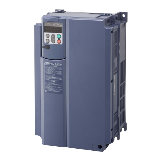
- Page 20 Chapter 1 BEFORE USE This chapter describes the check items before the use of the inverter. Contents Features ............................ 1-1 Control System........................1-15 1.2.1 Theory of inverter ......................1-15 1.2.2 Motor drive controls......................1-16 Acceptance Inspection ......................1-17 External View .......................... 1-18 Recommended Configuration ....................
-
Page 22: Features
1.1 Features Features Best vector control for the general-purpose inverter in the class Ideal for highly accurate control such as positioning Vector control with speed sensor Effective for applications requiring highly precise and accurate positioning control such as offset printing Speed control range: 1:1500 Speed response:... - Page 23 1.1 Features Fuji's original dynamic torque vector control has further upgraded Besides the dynamic torque vector control, the inverter is equipped with the motor parameter tuning for compensating even a voltage error of the main circuit devices and the magnetic flux observer of a new system.
- Page 24 1.1 Features Improved durability in overload operation Enhancement for extending the current overload durability time of the FRENIC-MEGA longer than that of the Fuji conventional inverters allows the FRENIC-MEGA to run the motor with shorter acceleration/deceleration time. This improves the operation efficiency of machinery such as cutting machines or carrier machines.
- Page 25 1.1 Features Accommodating various applications Convenient functions for operations at the specified speed Pulse train input speed command supported as standard The FRENIC-MEGA can issue a speed command with the pulse train input (single-phase pulse train with sign). (Maximum pulse input: 100 kHz) Ratio operation The ratio operation is convenient for synchronous control of two or more carrier machines in a multiline conveyor system.
- Page 26 1.1 Features Suppresses machine vibration with a notch filter By setting resonant frequency and attenuation, it is possible to suppress machine vibration. Optimum function for preventing an object from slipping down The reliability of the brake signal was increased for uses such as vertical carrier machines. Conventionally, the current value and the frequency have been monitored when the brake signal is output.
- Page 27 1.1 Features Thorough protection of the braking circuit The inverter monitors the braking transistor operation status to protect the braking resistor. Upon detection of a braking transistor abnormality, the inverter outputs an exclusive signal. Provide such a circuit that shuts the input power off upon receipt of the exclusive signal, outside the inverter for protecting the braking circuit.
- Page 28 1.1 Features Model variation that optimally satisfies customer needs Rich model variation 1. Basic type Suitable for the equipment that uses a peripheral device to noise or harmonics. 2. EMC filter built-in type This type has a built-in EMC filter and is compliant with European EMC Directives. Category C3 (2nd Env) IEC/EN61800-3:2004 compliant * Use of EMC filter will increase the leakage current.
- Page 29 DC reactor (DCR); if specified for LD mode, it is delivered with a built-in DCR as standard. * EMC filter built-in type and DC reactor built-in type are also available. Consult your Fuji Electric representative. For details, see Fuji Synchronous Motors & Inverter Synchronous Drive Systems Catalog (MH618) and/or Permanent Magnet Type Synchronous Motor Drive FRENIC-MEGA Instruction Manual (INR-SI47-1502).
- Page 30 * For inverters with capacities other than the above, contact your Fuji Electric representative. * The safety-compliant inverters are available on request. For the delivery schedule, contact your Fuji Electric representative. For details, see Safety-Compliant Inverters Catalog (MH668). 2. Comparison between safety-compliant models and standard models Table 1.1-1...
- Page 31 1.1 Features Supports for simple maintenance The built-in USB port allows use of an inverter support loader (FRENIC loader); Inverter support loader for easy information control! Improved working efficiency in the manufacturing site - A variety of data about the inverter body can be saved in the keypad memory, allowing you to check the information in any place.
- Page 32 1.1 Features Models: TP-G1-J1 * Multi-function keypads are available (Optional) TP-G1-C1 * Features * : Applicable model - LCD with a backlight that provides outstanding visibility FRENIC-Eco, Multi, MEGA - Large, seven-segment LED with five-digit display - Capable of adding and deleting quick setup items - Remote/local switching on the keypad - Data of up to three inverters can be copied - Languages...
- Page 33 1.1 Features Prolonged service life and improved life judgment function Designed life: 10 years The designed lives of the various consumable parts inside the FRENIC-MEGA have been extended to 10 years, which has also extended the equipment maintenance cycles. Consumable part Designed life Main circuit capacitor 10 years...
- Page 34 1.1 Features Consideration for environment Enhancing resistance to the environmental impact Resistance to the environmental impact has been enhanced compared with the conventional inverter. (1) Enhanced durability of the cooling fan operated under the environmental impact (2) Adoption of copper bars plated with nickel or tin In FRENIC-MEGA, resistance to the environmental impact has been increased compared with the conventional model (FRENIC5000 G11S/P11S).
- Page 35 1.1 Features Complies with the RoHS Directive Our inverters comply with the EU Directive on the restriction of the use of certain hazardous substances (RoHS Directive) as standard, and are environment-friendly with restricted use of the six hazardous substances. <Six hazardous substances> Lead, mercury, cadmium, hexavalent chromium, Polybrominated Biphenyls (PBBs), and Polybrominated Dephenyl Ethers (PBDEs) * This excludes components used for certain models.
-
Page 36: Control System
1.2 Control System Control System 1.2.1 Theory of inverter As shown in Figure 1.2-1, the converter section converts the input commercial power to DC power by means of a full-wave rectifier, which charges the DC link bus capacitor (reservoir capacitor). The inverter section modulates the electric energy charged in the DC link bus capacitor by Pulse Width Modulation (PWM) according to the control circuit signals and feeds the output to the motor. -
Page 37: Motor Drive Controls
1.2 Control System 1.2.2 Motor drive controls The FRENIC-MEGA supports the following motor drive controls. Table 1.2-1 Drive Basic Speed Other Motor drive controls control Speed control restrictions control feedback class V/f control with slip Frequency ― control compensation inactive Dynamic torque Disable ―... -
Page 38: Acceptance Inspection
1.3 Acceptance Inspection Acceptance Inspection Upon arrival of the inverter, unpack the package and check the following: (1) An inverter and the following accessories are contained in the package. Accessories • DC reactor (for 55-kW LD mode and for 75 kW or above) •... -
Page 39: External View
1st week of January as '01'. Production year: Last digit of year If you suspect the product is not working properly or if you have any questions about your product, contact your Fuji Electric representative. External View (1) Outside and inside views Figure 1.4... - Page 40 1.4 External View Warning plates and label FRN11G1S-2J FRN220G1S-4J Warning label Warning label (Above the heat sink) Figure 1.4-3 Warning plates and label 1-19...
-
Page 41: Installation And Wiring
1.4 External View View of the wiring section (a) FRN11G1S-2J (b) FRN30G1S-2J Figure 1.4 View of the wiring section (a) FRN0.75G1S-2J (b) FRN30G1S-2J Figure 1.4-5 Extended view of the terminal block For the functions, layout and connection of terminals, refer to Chapter 2, "INSTALLATION AND WIRING."... -
Page 42: Recommended Configuration
1.5 Recommended Configuration Recommended Configuration To control a motor with an inverter correctly, you should consider the rated capacity of both the motor and the inverter and ensure that the combination matches the specifications of the machine or system to be used. -
Page 43: Precautions For Using Inverters
1.6 Precautions for Using Inverters Precautions for Using Inverters 1.6.1 Operating environment Install the inverter in an environment that satisfies the requirements listed below. Table 1.6-1 Environmental Requirements Item Specifications Location Indoors Surrounding -10 to +50°C (Note 1) temperature Relative 5 to 95% (No condensation) humidity Ambience... -
Page 44: Storage Environment
1.6 Precautions for Using Inverters 1.6.2 Storage environment Temporary storage Store the inverter in an environment that satisfies the requirements listed below. Table 1.6-3 Storage and Transport Environments Item Specifications Storage temperature -25 to +70°C Places not subjected to abrupt temperature changes (Note 1) or condensation or freezing Relative humidity... -
Page 45: Precautions In Introducing Inverters
Install the inverter in an environment that satisfies the requirements listed in Table 1.6-1 in Section 1.6.1. Fuji Electric strongly recommends installing inverters in a panel for safety reasons, in particular, when installing the ones whose enclosure rating is IP00. -
Page 46: Operation
For an inverter with an output circuit filter installed, the total secondary wiring length should be 400 m or less (100 m or less under the vector control). If further longer secondary wiring is required, consult your Fuji Electric representative. Precautions for surge voltage in driving a motor by an inverter (especially for 400 V class,... -
Page 47: Function Codes
1.6 Precautions for Using Inverters Precautions for connection of peripheral equipment Phase-advancing capacitors for power factor correction Do not mount a phase-advancing capacitor for power factor correction in the inverter's input (primary) circuit. Mounting it in the input (primary) circuit takes no effect. To correct the inverter power factor, use an optional DC reactor (DCR). - Page 48 1.6 Precautions for Using Inverters Molded case circuit breaker (MCCB) Install a recommended molded case circuit breaker (MCCB) or an earth leakage circuit breaker (ELCB) (with overcurrent protection function) in the primary circuit of the inverter to protect wiring. Since using an MCCB or ELCB with a lager capacity than recommended ones breaks the protective coordination of the power supply system, be sure to select recommended ones.
- Page 49 1.6 Precautions for Using Inverters Noise reduction If noise generated from the inverter affects other devices, or that generated from peripheral equipment causes the inverter to malfunction, follow the basic measures outlined below. (1) If noise generated from the inverter affects the other devices through power wires or grounding wires: •...
-
Page 50: Precautions In Running Inverters
1.6 Precautions for Using Inverters 1.6.4 Precautions in running inverters Precautions for running inverters to drive motors or motor-driven machinery are described below. Motor temperature When an inverter is used to run a general-purpose motor, the motor temperature becomes higher than when it is operated with a commercial power supply. - Page 51 If the power transmission mechanism uses an oil-lubricated gearbox or speed changer/reducer, then continuous operation at low speed may cause poor lubrication. Avoid such operation. Synchronous motors It is necessary to take special measures suitable for this motor type. Contact your Fuji Electric representative for details. Single-phase motors Single-phase motors are not suitable for inverter-driven variable speed operation.
- Page 52 Chapter 2 INSTALLATION AND WIRING This chapter describes the important points in installing and wiring inverters. Contents Installation ..........................2-1 Wiring ............................2-3 2.2.1 Connection diagrams ......................2-3 Running a standard motor.................... 2-3 Running a Fuji motor exclusively designed for vector control........2-5 2.2.2 Removing and mounting the front cover and the wiring guide...........
-
Page 54: Installation
2.1 Installation Installation (1) Installation Surface Please install the inverter on non-combustible matter such as metals. Also, do not mount it upside down or horizontally. Install on non-combustible matter such as metals. Risk of fire exists. (2) Surrounding Space Secure the space shown in Figure 2.1-1 and Table 2.1-1. When enclosing FRENIC-MEGA in control panels, be sure to provide adequate board ventilation, as the surrounding temperature may rise. - Page 55 2.1 Installation To install the 30 kW or greater inverter with external cooling, change the mounting position of the mounting bases following the procedure below. (Refer to Figure 2.1-3) As the type and number of screws differ by inverter type, please review the following table. Table 2.1-2 Type and Number of Screws, and Tightening Torque Tightening Mounting base fixation...
-
Page 56: Wiring
2.2 Wiring Wiring Route the wiring following the steps below. (The inverter is already installed in the descriptions.) The inverter type is shown as "FRN***G1 -2J/4J" in the tables of this document. The box replaces an alphabetic character indicating the type. 2.2.1 Connection diagrams Running a standard motor... - Page 57 2.2 Wiring Install a recommended molded case circuit breaker (MCCB) or earth leakage circuit breaker (ELCB) (with overcurrent protective function) on the primary circuit of the inverter to protect wiring. Ensure that the circuit breaker capacity is equivalent to or lower than the recommended capacity. Install a recommended magnetic contactor (MC) for each inverter to separate the inverter from the power supply, apart from the MCCB or ELCB, when necessary.
-
Page 58: Running A Fuji Motor Exclusively Designed For Vector Control
2.2 Wiring Running a Fuji motor exclusively designed for vector control Figure 2.2-2... - Page 59 2.2 Wiring Install a recommended molded case circuit breaker (MCCB) or earth leakage circuit breaker (ELCB) (with overcurrent protective function) in the primary circuit of the inverter to protect wiring. Ensure that the circuit breaker capacity is equivalent to or lower than the recommended capacity. Install a recommended magnetic contactor (MC) for each inverter to separate the inverter from the power supply, apart from the MCCB or ELCB, when necessary.
-
Page 60: Removing And Mounting The Front Cover And The Wiring Guide
2.2 Wiring 2.2.2 Removing and mounting the front cover and the wiring guide (1) Types with a capacity of 22 kW or below 1) Loosen the screws of the front cover. Hold both sides of the front cover with the hands, slide the cover downward, and pull. -
Page 61: Wiring Precautions
2.2 Wiring 2.2.3 Wiring precautions Exercise caution for the following when wiring. (1) Confirm that the supply voltage is within the input voltage range described on the rating plate. (2) Always connect the power lines to the inverter main power input terminals L1/R, L2/S, L3/T (3 phase). (The inverter will be damaged when power is applied while the power lines are connected to the wrong terminals.) (3) Always route the ground line to prevent accidents such as electric shock and fire and to reduce noise. - Page 62 2.2 Wiring (9) The input terminals L2/S of inverters with a capacity of 500 kW and 630 kW are arranged in a direction perpendicular to the unit. To connect wires to the terminals, use the supplied bolts, washers and nuts as shown in the figure below.
-
Page 63: Main Circuit Terminals
2.2 Wiring 2.2.4 Main circuit terminals Screw specifications and recommended wire size (main circuit terminals) The specifications for the screws used in the main circuit wiring and the wire sizes are shown below. Exercise caution as the terminal layout varies by inverter capacity. In the diagram, the two ground terminals [ G] are not differentiated for the input side (primary side) and the output side (secondary side). - Page 64 2.2 Wiring When the inverter power is ON, a high voltage is applied to the following terminals. Main circuit terminals: L1/R, L2/S, L3/T, P1, P(+), N(-), DB, U, V, W, R0, T0, R1, T1, AUX-contact (30A, 30B, 30C, Y5A, Y5C) Insulation level Main circuit -...
-
Page 65: Terminal Layout Diagrams (Main Circuit Terminals)
2.2 Wiring Terminal layout diagrams (main circuit terminals) * Grounding terminal for input line provided only on the EMC filter built-in type Figure 2.2-10 2-12... - Page 66 2.2 Wiring Table 2.2-2 Recommended Wire Sizes Recommended wire size (mm Nominal Inverter type Main circuit power input Braking applied Grounding Inverter [L1/R, L2/S, L3/T] resistor motor output (kW) [ G] [U, V, W] HD mode LD mode MD mode [P1, P(+)] [P(+), DB] FRN0.4G1 -2J...
- Page 67 2.2 Wiring Table 2.2-3 Terminals common to all inverter Recommended wire Remarks types size (mm Auxiliary control power input 1.5 kW or above terminals [R0, T0] 200 V class series with Auxiliary fan power input 37 kW or above and 400 V terminals [R1, T1] class series with 75 kW or above...
-
Page 68: Description Of Terminal Functions (Main Circuit Terminals)
2.2 Wiring Description of terminal functions (main circuit terminals) Table 2.2-4 Symbol Name Functional description L1/R, L2/S, Main circuit power Connect the three-phase input power lines. L3/T input U, V, W Inverter output Connect a three-phase motor. R0, T0 Auxiliary power For a backup of the control circuit power supply, connect AC input... - Page 69 2.2 Wiring When multiple combinations of inverters and motors exist, do not use multi-core cables for the purpose of bundling the various wires. Figure 2.2-11 (3) Direct current reactor connection terminals P1, P(+) Connect a DC reactor (DCR) for correcting power factor. 1) Remove the jumper bar from the circuit terminals P1 and P(+).
- Page 70 MC which allows manual disconnection of the power source is recommended. If you wish to use a single-phase power source to supply power, consult your Fuji Electric representative. (7) Auxiliary control power input terminals R0, T0 (1.5 kW or above) The inverter can run without power input to the auxiliary power input terminals for control circuit.
- Page 71 2.2 Wiring When connecting an earth leakage breaker, connect terminals R0, T0 to the output side of the earth leakage breaker. When connections are made to the input side of the earth leakage breaker, the earth leakage breaker will malfunction because the inverter input is 3 phase and the terminals R0, T0 are single phase.
-
Page 72: Control Circuit Terminals (Common To All Inverter Types)
2.2 Wiring 2.2.5 Control circuit terminals (common to all inverter types) Screw specifications and recommended wire size (control circuit terminals) The specifications for the screws used in the control circuit wiring and the wire size are shown below. The control circuit terminal blocks are common to all inverter types regardless of their capacities. Table 2.2-8 Screw Specifications and Recommended Wire Size Screw specifications Recommended wire size... -
Page 73: Notes On Control Circuit Wiring
2.2 Wiring Notes on control circuit wiring For FRN75G1S-2J, FRN90G1S-2J, and FRN132G1S-4J to FRN630G1S-4J (1) As shown in Figure 2.2-16, run the wires along the left-side panel of the inverter. (2) Secure the wires to the wire fixing holders with cable ties (wire bands, etc.). The cable ties should be max. -
Page 74: Terminal Functions (Control Circuit)
2.2 Wiring Terminal functions (control circuit) Analog input terminals Table 2.2-9 Symbol Name Functional description Power supply (+10 VDC) for frequency command potentiometer [13] Power supply for (Potentiometer: 1 to 5 kΩ) the potentiometer The potentiometer of 1/2 W rating or more should be connected. (1) The frequency is commanded according to the external [12] Analog setting... - Page 75 2.2 Wiring Table 2.2-10 Symbol Name Functional description (1) The frequency is commanded according to the external [C1] Analog setting analog current input. current input • 4 to 20 mA DC/0 to 100%, 0 to 20 mA DC/0 to 100% *4 (C1 function) (Normal operation) •...
- Page 76 2.2 Wiring Table 2.2-11 Symbol Name Functional description [V2] PTC/NTC (1) Connects PTC (Positive Temperature Coefficient)/NTC thermistor input (Negative Temperature Coefficient) thermistor for motor protection. Ensure that the slide switch SW5 on the control (PTC/NTC PCB is turned to the PTC/NTC position (refer to Section function) 2.2.7 "Setting up the slide switches").
- Page 77 2.2 Wiring Digital input terminals Table 2.2-12 Symbol Name Functional description [X1] Digital input 1 (1) Various signals such as "Coast to a stop," "Enable external alarm trip," and "Select multi-frequency" can [X2] Digital input 2 be assigned to terminals by setting function codes E01 to E09, E98, and E99.
- Page 78 2.2 Wiring Table 2.2-14 Symbol Name [PLC] PLC signal (1) Connects to PLC output signal power supply. power Rated voltage: +24 VDC (Allowable range: +22 to +27 VDC), Maximum 100 mA DC (2) The terminal can also be used as a power source for the load connected to the transistor output.
- Page 79 2.2 Wiring Table 2.2-15 Symbol Name Functional description (a) With the switch turned to SINK (b) With the switch turned to SOURCE Figure 2.2-22 Circuit Configuration Using a PLC For details about the slide switch setting, refer to Section 2.2.7 "Setting up the slide switches."...
- Page 80 2.2 Wiring Analog output, pulse output, transistor output, and relay output terminals Table 2.2-16 Symbol Name Functional description The monitor signal for analog DC voltage (0 to +10 V) or analog [FMA] Analog monitor DC current (+4 to +20 mA or 0 to +20 mA *4) is output. You can (FMA function) select the output form (VO/IO) by switching the slide switch SW4 on the control PCB and changing data of the function code F29.
- Page 81 2.2 Wiring Pulse signal is output. You can also select one of the signal [FMP] Pulse monitor functions listed in the above column for [FMA] using function (FMP function) code F35. * Input impedance of the external device: Min. 5 kΩ (While the terminal is outputting 0 to 10 VDC, it is capable of driving up to two analog voltmeters with 10 kΩ...
- Page 82 2.2 Wiring Table 2.2-17 Symbol Name Functional description (1) Various signals such as Inverter Running, Frequency Arrival [Y1] Transistor and Overload Early Warning can be output from these output 1 terminals by setting function code E20 to E24. Refer to [Y2] Transistor Chapter 5 "FUNCTION CODES"...
- Page 83 2.2 Wiring Table 2.2-19 Symbol Name Functional description Connecting programmable logic controller (PLC) to terminal [Y1], [Y2], [Y3] or [Y4] Figure 2.2-26 shows two examples of circuit connection between the transistor output of the inverter's control circuit and a PLC. In example (a), the input circuit of the PLC serves as a SINK for the control circuit output, whereas in example (b), it serves as a SOURCE for the output.
- Page 84 2.2 Wiring RS-485 communications port Table 2.2-20 Connector Name Functions A communications port transmits data through the RS-485 DX+/DX- RS-485 multipoint protocol between the inverter and a personal computer communicatio or other equipment such as a PLC. (For setting of the terminating ns port 2 resistor, refer to Section 2.2.7 "Setting up the slide switches.") (Terminals on...
-
Page 85: Switching Connectors
2.2 Wiring 2.2.6 Switching connectors Power supply switching connector "CN UX" (400 V class series with 75 kW or above) The power supply switching connector "CN UX" is equipped on inverters of 75 kW or above in 400 V class series. When the power supply connecting to the main power supply input terminals (L1/R, L2/S, L3/T) or the auxiliary power input terminals for the fan (R1, T1) meets the following requirements, move the connector CN UX to U2 side. - Page 86 2.2 Wiring Fan power source switching connector "CN R", "CN W" (200 V class series with 37 kW or above, 400 V class series with 75 kW or above) FRENIC-MEGA supports direct current power supply input with PWM converters in the standard specification. However, inverters of 37 kW or above in 200 V class series and 75 kW or above in 400 V class series contain parts which are driven by AC power supply such as the AC fan, so AC power must also be supplied.
- Page 87 2.2 Wiring Position of each connector The individual switching connectors are positioned on the power supply printed circuit board as shown in the figure below. Power supply switching Keypad enclosure connector "CN UX" Fan power source switching connectors Auxiliary power input Auxiliary terminal for power input...
-
Page 88: Setting Up The Slide Switches
2.2 Wiring 2.2.7 Setting up the slide switches Before changing the switches, turn OFF the power and wait at least five minutes for inverters with a capacity of 22 kW or below, or at least ten minutes for inverters with a capacity of 30 kW or above. Make sure that the LED monitor and charging lamp are turned OFF. - Page 89 2.2 Wiring <Switches the property of the analog input terminal [V2]> This switches the property of the terminal between analog setting voltage input, PTC thermistor input, and NTC thermistor input. When changing this switch setting, also change the data of function code H26. Table 2.2-23 Set data of H26 to: Output mode...
-
Page 90: Attachment And Connection Of Keypad
2.3 Attachment and Connection of Keypad Attachment and Connection of Keypad You can remove the keypad from the inverter main body to mount it on the board or remotely control it at hand. Figure2.3-1 Attaching the Keypad on the Board The following parts are necessary when attaching the keypad to locations other than the inverter main body. -
Page 91: Protective Functions
2.4 Protective Functions Protective Functions The table below lists the name of the protective functions, description, and alarm codes on the LED monitor. If an alarm code appears on the LED monitor, remove the cause of activation of the alarm function referring to Chapter 6 "TROUBLESHOOTING."... - Page 92 2.4 Protective Functions Overheat Stops the inverter output upon detecting excess heat sink protection temperature in case of cooling fan failure or overload. Detects a failure of the internal air circulation DC fan and stops the inverter. (For models of 45 kW in 200 V class series and 75 kW or above in 400 V class series) Stops the inverter output upon detecting an excessively high surrounding temperature inside the inverter caused by a failure or an...
- Page 93 2.4 Protective Functions Table 2.4-2 Alarm output [30A/B/C] Name Description monitor (Note) displays Overspeed - When d35 = 999, stops the inverter if the detected speed is 120% or over of the maximum output frequency × (d32 or d33). *1 to *4 - When d35 ≠...
- Page 94 2.4 Protective Functions Operation STOP Pressing the key on the keypad forces the inverter Yes* protection to decelerate and stop the motor even if the inverter is priority running by any run commands given via the terminals or communications (link operation). (After the motor stops, the inverter issues alarm Start To prevent a sudden start, the inverter prohibits any run...
- Page 95 2.4 Protective Functions Table 2.4-3 Alarm output [30A/B/C] Name Description monitor (Note) displays Tuning error During tuning of motor parameters, if the tuning has failed or has detection been aborted, or an abnormal condition has been detected in the tuning result, the inverter stops its output. RS-485 When the inverter is connected to a communications network via the Yes*...
- Page 96 2.4 Protective Functions Note: In Alarm output [30A/B/C] column, "Yes*" means that an alarm may not be issued depending upon function code setting. *1 Available under V/f control with speed sensor. (PG option required) *2 Available under dynamic torque vector control with speed sensor. (PG option required) *3 Available under vector control without speed sensor.
- Page 97 2.4 Protective Functions Table 2.4-4 Alarm output [30A/B/C] Name Description monitor (Note) displays l-al Light alarm The "light-alarm" display is indicated when alarm or warning (warning) matters set as minor troubles occurred. The operation is continued. Light alarm object Heat sink overheat( ), External alarm ( ), Inverter internal overheat(...
-
Page 98: Reading Maintenance Information
Chapter 3 KEYPAD FUNCTIONS (OPERATING WITH THE KEYPAD) This chapter describes the names and functions of the keypad and inverter operation using the keypad. The inverter features three operation modes (Running, Programming and Alarm modes) which enable you to run and stop the motor, monitor running status, set function code data, display running information required for maintenance, and display alarm data. -
Page 100: Led Monitor, Keys And Led Indicators On The Keypad
3.1 LED Monitor, Keys and LED Indicators on the Keypad LED Monitor, Keys and LED Indicators on the Keypad The keypad allows you to run and stop 7-segment the inverter, display various data, LED monitor specify the function code data, and LED indicators UP key monitor I/O signal states, maintenance... - Page 101 3.1 LED Monitor, Keys and LED Indicators on the Keypad LED Monitor, Keys, Functions Item and LED Indicators Hz, A, kW, r/min, m/min: The unit of numeral displayed on the LED monitor in Running mode is identified by combination of lit and unlit states of these three LED indicators. Refer to Section 3.3.1 Unit LEDs "Monitoring the running status"...
- Page 102 3.1 LED Monitor, Keys and LED Indicators on the Keypad LED monitor In Running mode, the LED monitor displays running status information (output frequency, current or voltage); in Programming mode, it displays menus, function codes and their data; and in Alarm mode, it displays an alarm code which identifies the alarm factor if the protective function is activated.
-
Page 103: Overview Of Operation Modes
3.2 Overview of Operation Modes Overview of Operation Modes FRENIC-MEGA features the following three operation modes: Running mode: After powered ON, the inverter automatically enters this mode. This mode allows you to specify the reference frequency, PID command value and etc., and run/stop the motor with the keys. - Page 104 3.2 Overview of Operation Modes The figure below illustrates the transition of the LED monitor screen during Running mode, the transition between menu items in Programming mode, and the transition between alarm codes at different occurrences in Alarm mode. (*1) The speed monitor allows you to select the desired one from the speed monitor items by using function code E48.
-
Page 105: Running Mode
3.3 Running Mode Running Mode When the inverter is turned on, it automatically enters Running mode in which you can: (1) Monitor the running status (e.g., output frequency and output current), (2) Configure the reference frequency and other settings, (3) Run/stop the motor, (4) Jog (inch) the motor, (5) Switch between remote and local modes, and (6) Monitor light alarms... - Page 106 3.3 Running Mode An analog input to the inverter in a format suitable for a desired Analog input scale. 8"00 Hz A kW monitor (*8) Refer to function codes E40 and E41 for details. Torque current command value or Torque current Hz A kW (*9) calculated torque command...
-
Page 107: Monitoring Light Alarms
3.3 Running Mode 3.3.2 Monitoring light alarms The FRENIC-MEGA identifies abnormal states in two categories--Heavy alarm and Light alarm (displayed on digital output terminals). If the former occurs, the inverter immediately trips; if the latter occurs, the l-al inverter shows the on the LED monitor and blinks the KEYPAD CONTROL LED but it continues to run without tripping. -
Page 108: Setting Up Frequency And Pid Commands
3.3 Running Mode 3.3.3 Setting up frequency and PID commands You can set up the desired frequency and PID commands by using keys on the keypad. It is also possible to set up the frequency command as load shaft speed by setting function code E48. Setting up a frequency command Using the keypad (F01 = 0 (factory default) or 8) Set function code F01 to "0"... - Page 109 3.3 Running Mode • To input bipolar analog voltage (0 to ±10 VDC) to terminals [12] and [V2], set C35 and C45 data to "0." Setting C35 and C45 data to "1" enables the voltage range from 0 to +10 VDC and interprets the negative polarity input from 0 to -10 VDC as 0 V.
- Page 110 3.3 Running Mode Table 3.3-2 PID Process Command Manually Set with Key and Requirements PID control PID control LED monitor Multi-frequency (Mode selection) (Remote command SV) With SS4, SS8 PID process command by keypad Other than 1 or 2 Other than 0 PID process command currently selected Setting up the frequency command with keys under PID process control...
- Page 111 3.3 Running Mode Settings under PID dancer control To enable the PID dancer control, you need to set the J01 data to "3." Under the PID control, the items that can be specified or checked with keys differ depending upon the current LED monitor setting. If the LED monitor is set to the speed monitor, the item accessible is the primary frequency command;...
- Page 112 3.3 Running Mode Setting up the primary frequency command with keys under PID dancer control When function code F01 is set to "0" ( keys on keypad) and frequency command 1 is selected as a primary frequency command (when disabling the frequency setting command via communications link, multi-frequency command, and PID control), switching the LED monitor to the speed monitor in Running mode enables you to modify the frequency command with the keys.
-
Page 113: Running/Stopping The Motor
3.3 Running Mode 3.3.4 Running/stopping the motor By factory default, pressing the key starts running the motor in the forward direction and pressing the decelerates the motor to stop. The key is enabled only in Running mode. The motor rotational direction can be selected by changing the setting of function code F02. -
Page 114: Remote And Local Modes
3.3 Running Mode 3.3.6 Remote and local modes The inverter is available in either remote or local mode. In the remote mode that applies to ordinary operation, the inverter is driven under the control of the data settings stored in the inverter, whereas in the local mode that applies to maintenance operation, it is separated from the control system and is driven manually under the control of the keypad. -
Page 115: External Run/Frequency Command
3.3 Running Mode 3.3.7 External run/frequency command By factory default, run commands ( keys) and frequency commands are sourced from the keypad. This section provides other external command source samples--an external potentiometer (variable resistor) as a frequency command source and external run switches as run forward/reverse command sources. -
Page 116: Programming Mode
3.4 Programming Mode Programming Mode The Programming mode provides you with these functions--setting and checking function code data, monitoring maintenance information and input/output (I/O) terminal status. The functions can be easily selected with the menu-driven system. Table 3.4-1 lists menus available in Programming mode. The leftmost digit (numerals) of each letter string on the LED monitor indicates the corresponding menu number and the remaining three digits indicate the menu contents. - Page 117 3.4 Programming Mode Figure 3.4-1 illustrates the menu transition in Programming mode. Table3.4-1 Menu Transition in Programming Mode 3-18...
-
Page 118: Setting Up Basic Function Codes Quickly "Quick Setup"
3.4 Programming Mode Selecting menus to display Function code E52 is available to cycle through necessary menus only for simple operation. The factory default (E52 = 0) is to display only three menus--Menu #0 "Quick Setup, "Menu #1 "Data Setting" and Menu #7 "Data Copying,"... - Page 119 3.4 Programming Mode Listed below are the function codes (including those not subject to quick setup) available on the FRENIC-MEGA. A function code is displayed on the LED monitor on the keypad in the following format: ID number in each function Function code group Figure 3.4-2 Table 3.4-3 Function Codes Available on FRENIC-MEGA...
- Page 120 3.4 Programming Mode Function codes requiring simultaneous keying To modify the data for function code F00 (Data Protection), H03 (Data Initialization), H45 (Mock Alarm), or H97 (Clear Alarm Data), simultaneous keying is needed, involving the keys or keys. Changing, validating, and saving function code data when the inverter is running Some function code data can be changed while the inverter is running, whereas others cannot.
-
Page 121: Setting Up Function Codes Menu #1 "Data Setting"
1 second or longer. This action is called "Cursor movement." It is possible to change or add function code items subject to quick setup. For details, consult your Fuji Electric representatives. 3.4.2 Setting up function codes Menu #1 "Data Setting"... - Page 122 3.4 Programming Mode (Note) The o codes are displayed only when the corresponding option is mounted. For details, refer to the Instruction Manual for the corresponding option. Figure 3.4-4 Menu Transition in Menu #1 "Data Setting" 3-23...
- Page 123 3.4 Programming Mode Basic key operation The basic key operation is just like that in Menu #0 "Quick Setup." Turn the inverter ON. It automatically enters Running mode. In that mode, press the key to switch to Programming mode. The function selection menu appears. !f__ Use the keys to display the desired function code group from the choices...
-
Page 124: Checking Changed Function Codes Menu #2 "Data Checking"
3.4 Programming Mode 3.4.3 Checking changed function codes Menu #2 "Data Checking" Menu #2 "Data Checking: "rep " in Programming mode allows you to check function codes that have been changed. Only the function codes whose data has been changed from the factory defaults are displayed on the LED monitor. -
Page 125: Monitoring The Running Status Menu #3 "Drive Monitoring"
3.4 Programming Mode 3.4.4 Monitoring the running status Menu #3 "Drive Monitoring" Menu #3 "Drive Monitoring" is used to monitor the running status during maintenance and trial running. The display items for "Drive Monitoring" are listed in Table 3.4-4. Figure 3.4-6 shows the menu transition in Menu #3 "Drive Monitoring."... - Page 126 3.4 Programming Mode Table 3.4-4 Drive Monitor Display Items LED monitor Unit Item Description shows: 3_00 Output frequency Output frequency before slip compensation 3_01 Output frequency Output frequency after slip compensation 3_02 Output current Output current 3_03 Output voltage Output voltage 3_04 Calculated torque Motor output torque in % (Calculated value)
- Page 127 3.4 Programming Mode LED monitor Item Unit Description shows: Current control status appears. Synchronous control disabled Synchronous control cancel Synchronous control stop Control state monitor 3_20 Wait for Z-phase detection (Synchronous operation) Basic Z-phase detection Slave Z-phase detection Synchronizing Completely synchronized PID output value appears.
- Page 128 3.4 Programming Mode 3_23 Table 3.4-6 Running Status 2 ( ) Bit Assignment Code Content Code Content Speed limiting (under torque control) (Not used.) Motor switching Motor 1 Motor 2 Motor 3 Motor 4 Inverter drive control 0000: V/f control with slip compensation inactive 0001: Dynamic torque vector control (Not used.)
-
Page 129: Checking I/O Signal Status Menu #4 "I/O Checking"
3.4 Programming Mode 3.4.5 Checking I/O signal status Menu #4 "I/O Checking" Using Menu #4 "I/O Checking" displays the I/O status of external signals on the LED monitor without using a measuring instrument. External signals that can be displayed include digital and analog I/O signals. Table 3.4-9 lists check items available. - Page 130 3.4 Programming Mode Basic key operation To check the status of the I/O signals, set function code E52 to "2" (Full-menu mode) beforehand. Turn the inverter ON. It automatically enters Running mode. In that mode, press the key to switch to Programming mode. The function selection menu appears. Press the key to display "I/O Checking"...
- Page 131 3.4 Programming Mode LED monitor Item Description PG pulse rate Shows the pulse rate (kp/s) of the A/B phase signal fed back from the 4_17 (A/B phase signal from slave PG. (Shows 1.00 with 1000 p/s.) the slave PG) PG pulse rate Shows the pulse rate (p/s) of the Z phase signal fed back from the slave 4_18 (Z phase signal from the...
- Page 132 3.4 Programming Mode Displaying I/O signal status in hexadecimal Each I/O terminal is assigned to bit 15 through bit 0 in 16-digit binary. An unassigned bit is interpreted as "0." Allocated bit data is displayed on the LED monitor as four hexadecimal digits ( each).
- Page 133 3.4 Programming Mode Displaying control circuit terminal on digital I/O interface cards The LED monitor can also show the signal status of the terminals on the optional digital input and output interface cards, just like the signal status of the control circuit terminals. Digital I/O signals are assigned to the LED segments, as follows: Table 3.4-12 Segment Display for External Signal Information (Digital Input and Output Interface Cards) LED4...
-
Page 134: Maintenance Information"
3.4 Programming Mode 3.4.6 Reading maintenance information Menu #5 "Maintenance Information" Menu #5 "Maintenance Information" ( %che ) contains information necessary for performing maintenance on the inverter. Figure 3.4-8 shows the menu transition in Menu #5 "Maintenance Information." Figure 3.4-8 Menu Transition in Menu #5 "Maintenance Information" Basic key operation To view the maintenance information, set function code E52 to "2"... -
Page 135: Maintenance And Inspection
3.4 Programming Mode Table 3.4-13 Display Items for Maintenance Information Item Description monitor Shows the content of the cumulative power-ON time counter of the inverter. Counter range: 0 to 65,535 hours Display: Upper 2 digits and lower 3 digits are displayed alternately. ⇔... - Page 136 3.4 Programming Mode Item Description monitor Shows the input watt-hour of the inverter. *001 9999 Display range: Input watt-hour = Displayed value × 100 kWh 5_09 Input watt-hour To reset the integrated input watt-hour and its data, set function code E51 to "0.000."...
- Page 137 3.4 Programming Mode Item Description monitor Shows the content of the cumulative power-ON time counter of motor 1. Counter range: 0 to 99,990 hours 9999 Display range: The x10 LED turns ON. Cumulative run time 5_23 of motor (Actual cumulative motor run time (hours) = Displayed value x 10) When the count exceeds 99,990, the counter will be reset to "0"...
- Page 138 3.4 Programming Mode Item Description monitor Shows the factor of the latest light alarm as an alarm code. Light alarm factor 5_36 (Latest) For details, refer to the description of H81 in Chapter 5. Shows the factor of the last light alarm as an alarm code. Light alarm factor 5_37 For details, refer to the description of H81 in Chapter 5.
-
Page 139: Reading Alarm Information Menu #6 "Alarm Information"
3.4 Programming Mode 3.4.7 Reading alarm information Menu #6 "Alarm Information" Menu #6 "Alarm Information" shows the causes of the past 4 alarms in alarm code. Further, it is also possible to display alarm information that indicates the status of the inverter when the alarm occurred. Figure 3.4-9 shows the menu transition in Menu #6 "Alarm Information"... - Page 140 3.4 Programming Mode Table 3.4-14 Alarm Information Displayed LED monitor Item Description (item No.) 6_00 Output frequency Output frequency before slip compensation 6_01 Output current Output current 6_02 Output voltage Output voltage 6_03 Calculated torque Calculated torque 6_04 Reference frequency Reference frequency Rotational direction being outputted 6_05...
- Page 141 3.4 Programming Mode LED monitor Item Description (item No.) No. of consecutive 6_15 The number of times the same alarm occurs consecutively. occurrences Simultaneously occurring alarm codes (1) 6_16 Multiple alarm 1 ("----" is displayed if no alarms have occurred.) Simultaneously occurring alarm codes (2) 6_17 Multiple alarm 2...
-
Page 142: Copying Data Menu #7 "Data Copying"
3.4 Programming Mode 3.4.8 Copying data Menu #7 "Data Copying" Menu #7 "Data Copying" is used to read function code data out of an inverter for storing it in the keypad to save configuration data or writing it into another inverter. It is also used to verify the function code data stored in the keypad with the one configured in the inverter. - Page 143 3.4 Programming Mode Basic key operation Turn the inverter ON. It automatically enters Running mode. In that mode, press the key to switch to Programming mode. The function selection menu appears. 'cpy Use the keys to display "Data Copying" ( read Press the key to proceed to the list of data copying functions (e.g.
- Page 144 3.4 Programming Mode When is blinking, press the key to get out of the error state. cper When is blinking, pressing FUNC/DATA key allows you to continue the operation. However, extended function code data cannot be changed. Data protection You can protect data saved in the keypad from unexpected modifications. Enabling the data protection that read proT was disabled changes the display...
- Page 145 3.4 Programming Mode cper (2) If is blinking, any of the following problems has arisen: The function codes stored in the keypad are not compatible with each other, cper is blinking. • If the inverter type is the same. The error occurs due to difference in software version. Pressing the key allows you to continue the copying operation.
-
Page 146: Alarm Mode
3.5 Alarm Mode Alarm Mode If an abnormal condition arises, the protective function is invoked and issues an alarm, then the inverter automatically enters Alarm mode. At the same time, an alarm code appears on the LED monitor. 3.5.1 Releasing the alarm and switching to Running mode Remove the cause of the alarm and press the key to release the alarm and return to Running mode. - Page 147 3.5 Alarm Mode Figure 3.5-1 summarizes the possible transitions between different menu items. Figure 3.5-1 Menu Transition in Alarm Mode 3-48...
-
Page 148: Usb Connectivity
3.6 USB Connectivity USB Connectivity The keypad has a USB port (mini B connector) on its face. To connect a USB cable, open the USB port cover as shown below. Connecting the inverter to a PC with a USB cable enables remote control from FRENIC Loader. On the PC running FRENIC Loader, it is possible to edit, check, manage, and monitor the function code data in real-time, to start or stop the inverter, and to monitor the running or alarm status of the inverter. - Page 150 Chapter 4 OPERATION Contents Test Run ............................ 4-1 4.1.1 Test run procedure ......................4-1 4.1.2 Checking prior to powering on ................... 4-2 4.1.3 Powering on and checking ....................4-2 4.1.4 Selecting an inverter drive mode (HD/MD/LD)..............4-3 4.1.5 Selecting a motor drive control................... 4-4 4.1.6 Basic settings of function codes <...
-
Page 152: Test Run
4.1 Test Run Test Run 4.1.1 Test run procedure Make a test run of the motor using the flowchart given below. This chapter describes the test run procedure with motor 1 dedicated function codes that are marked with an asterisk (*). For motors 2 to 4, replace those asterisked function codes with motor 2 to 4 dedicated ones. For the function codes dedicated to motors 2 to 4, see Chapter 5 "FUNCTION CODES."... -
Page 153: Checking Prior To Powering On
4.1 Test Run 4.1.2 Checking prior to powering on Check the following before powering on the inverter. Check that the wiring is correct. Especially check the wiring to the inverter input terminals L1/R, L2/S and L3/T and output terminals U, V, and W. Also check that the grounding wires are connected to the grounding terminals ( G) correctly. -
Page 154: Selecting An Inverter Drive Mode (Hd/Md/Ld)
4.1 Test Run 4.1.4 Selecting an inverter drive mode (HD/MD/LD) The FRENIC-MEGA inverter is available in three different drive modes; HD (High Duty: for heavy duty load applications), MD (Medium Duty: for medium duty load applications), and LD (Low Duty: for light duty load applications), and the user can switch the drive modes on site. -
Page 155: Selecting A Motor Drive Control
4.1 Test Run 4.1.5 Selecting a motor drive control The FRENIC-MEGA supports the following motor drive controls. Table 4.1-3 Drive F42 * Basic Speed Drive control control Speed control Other restrictions data control feedback type V/f control with slip compensation Frequency ―... - Page 156 4.1 Test Run Dynamic torque vector control To get the maximal torque out of a motor, this control calculates the motor torque for the load applied and uses it to optimize the voltage and current vector output. Selecting the dynamic torque vector control automatically enables the auto-torque boost and slip compensation.
- Page 157 4.1 Test Run Vector control with speed sensor The inverter is equipped with an optional PG (Pulse Generator) interface card and receives the feedback signals from the PG to detect the motor rotational position and speed for speed control. In addition, it decomposes the motor drive current into the exciting and torque current components, and controls each of those components in vector.
- Page 158 The final performance should be determined by adjusting the speed control system or other elements with the inverter being connected to the machinery (load). If you have any questions, contact your Fuji Electric representative.
-
Page 159: Basic Settings Of Function Codes < 1
4.1 Test Run 4.1.6 Basic settings of function codes < 1 > Driving a Fuji general-purpose motor under the V/f control (F42 * = 0 or 2) or dynamic torque vector control (F42 * = 1) requires configuring the following basic function codes. Select Fuji standard 8- or 6-series motors with the function code P99 * . -
Page 160: Basic Settings/Tuning Of Function Codes < 2
4.1 Test Run 4.1.7 Basic settings/tuning of function codes < 2 > Under the V/f control (F42 * = 0 or 2) or dynamic torque vector control (F42 * = 1), when a non-Fuji motor or non-standard motor is driven, or a Fuji general-purpose motor is driven and the wiring distance between the inverter and motor is long or a reactor is connected, the basic function codes should be configured and auto-tuning should be performed for controlling the motor before operation. - Page 161 4.1 Test Run Tuning procedure Selection of tuning type Check the situation of the machinery and select "Tuning with the motor stopped (P04 = 1)" or "Tuning with the motor running (P04 = 2)." For the latter tuning, adjust the acceleration and deceleration times (F07 and F08) and specify the rotation direction that matches the actual rotation direction of the machinery.
- Page 162 Other errors An undervoltage or any other alarm has occurred. If any of these errors occurs, remove the error cause and perform tuning again, or consult your Fuji Electric representative. If a filter other than the Fuji optional output filter (OFL- - A) is connected to the inverter's output (secondary) circuit, the tuning result cannot be assured.
-
Page 163: Basic Settings/Tuning Of Function Codes < 3
4.1 Test Run 4.1.8 Basic settings/tuning of function codes < 3 > When using "vector control without speed sensor (F42 =5), auto-tuning should be performed without regard to the motor type (including the Fuji motors (VG motors) exclusively designed for vector control. Configure the function codes listed below according to the motor ratings and your machinery design values. - Page 164 4.1 Test Run Tuning procedure Selection of tuning type Check the situation of the machinery and select "Tuning with the motor running (P04 = 3)." For the latter tuning, adjust the acceleration and deceleration times (F07 and F08) and specify the rotation direction that matches the actual rotation direction of the machinery.
- Page 165 4.1 Test Run 2) Enter a run command. (The factory default is key on the keypad for forward rotation. To switch to reverse rotation or to select the terminal signal FWD or REV as a run command, change the data of function code F02.) 3) The moment a run command is entered, the display of lights up, and tuning starts with the motor...
- Page 166 2) Set the motor parameters (P06 * and P16 * to P23 * ) by referencing the motor test report. For details about converting the test report values into various parameters, consult your Fuji Electric representative.
- Page 167 Other errors An undervoltage or any other alarm has occurred. If any of these errors occurs, remove the error cause and perform tuning again, or consult your Fuji Electric representative. If a filter other than the Fuji optional output filter (OFL- - A) is connected to the inverter's output (secondary) circuit, the tuning result cannot be assured.
-
Page 168: Basic Settings Of Function Codes < 4
4.1 Test Run 4.1.9 Basic settings of function codes < 4 > When using "vector control with speed sensor (F42 * =6)" and combining the inverter with the Fuji motors (VG motors) exclusively designed for vector control, set the function code data as listed below. For details on how to modify the function code data, see Chapter 3, Section 3.4.2 "Setting up function codes Menu #1 “Data Setting”."... -
Page 169: Basic Settings Of Function Codes < 5
4.1 Test Run 4.1.10 Basic settings of function codes < 5 > When driving a Fuji general-purpose motor under "V/f control with speed sensor (F42 * = 3)" or "dynamic torque vector control with speed sensor (F42 * = 4)," the following basic function codes should be set. Select Fuji standard 8- or 6-series motors with the function code P99 * . -
Page 170: Basic Settings/Tuning Of Function Codes < 6
4.1 Test Run 4.1.11 Basic settings/tuning of function codes < 6 > Under the V/f control with speed sensor (F42 * = 3) or dynamic torque vector control with speed sensor (F42 * = 4), when a non-Fuji motor or non-standard motor is driven, or a Fuji general-purpose motor is driven and the wiring distance between the inverter and motor is long or a reactor is connected, the basic function codes should be configured and auto-tuning should be performed for controlling the motor before operation. - Page 171 4.1 Test Run Tuning procedure (1) Selection of tuning type Check the situation of the machinery and select "Tuning with the motor stopped (P04 = 1)" or "Tuning with the motor running (P04 = 2)." For the latter tuning, adjust the acceleration and deceleration times (F07 and F08) and specify the rotation direction that matches the actual rotation direction of the machinery.
- Page 172 Other errors An undervoltage or any other alarm has occurred. If any of these errors occurs, remove the error cause and perform tuning again, or consult your Fuji Electric representative. If a filter other than the Fuji optional output filter (OFL- - A) is connected to the inverter's output (secondary) circuit, the tuning result cannot be assured.
-
Page 173: Running The Inverter For Motor Operation Check
4.1 Test Run 4.1.12 Running the inverter for motor operation check If the user configures the function codes wrongly without completely understanding this User's Manual, the motor may rotate with a torque or at a speed not permitted for the machine. Accident or injury may result. - Page 174 4.1 Test Run <Modification of motor control function code data> Modifying the current function code data sometimes can solve an insufficient torque or overcurrent incident. The table below lists the major function codes to be accessed. For details, see Chapter 5 "FUNCTION CODES"...
-
Page 175: Preparation For Production Run
4.1 Test Run 4.1.13 Preparation for production run After checking that the motor runs normally in test runs, connect the inverter to the machinery and cable them for production run. (1) Set the function codes for application to run the machinery. (2) Check the interfaces with the peripheral circuits. -
Page 176: Special Operation
4.2 Special Operation Special Operation 4.2.1 Jogging operation This section provides the procedure for jogging the motor. Making the inverter ready to jog with the steps below. (The LED monitor should display • Enter Running mode. (See page 3-1.) • Press the keys simultaneously. -
Page 177: Remote And Local Modes
4.2 Special Operation 4.2.2 Remote and local modes The inverter is available in either remote or local mode. In the remote mode that applies to ordinary operation, the inverter is driven under the control of the data settings stored in the inverter, whereas in the local mode that applies to maintenance operation, it is separated from the control system and is driven manually under the control of the keypad. -
Page 178: External Run/Frequency Command
4.2 Special Operation 4.2.3 External run/frequency command By factory default, the run and frequency commands are sourced from the keypad ( keys). This section provides other external command source samples; an external potentiometer (variable resistor) as a frequency command source and external run switches as run forward/reverse command sources. - Page 180 Chapter 5 FUNCTION CODES This chapter contains overview tables of function codes available for the FRENIC-MEGA series of inverters, function code index by purpose, and details of function codes. Contents Overview of Function Codes ..................... 5-1 Function Code Tables........................ 5-2 Code Index by Purpose......................
- Page 181 5.3.18 Maintenance........................5-59 Maintenance of inverters ....................5-59 Maintenance of machinery....................5-60 Details of Function Codes ....................... 5-61 5.4.1 F codes (Fundamental functions)..................5-61 5.4.2 E codes (Terminal functions)..................5-122 5.4.3 C codes (Control functions).................... 5-166 5.4.4 P codes (Motor 1 parameters)..................5-175 5.4.5 H codes (High performance functions)................
-
Page 182: Overview Of Function Codes
5.1 Overview of Function Codes Overview of Function Codes Function codes enable the FRENIC-MEGA series of inverters to be set up to match your system requirements. Each function code consists of a 3-letter alphanumeric string. The first letter is an alphabet that identifies its group and the following two letters are numerals that identify each individual code in the group. -
Page 183: Function Code Tables
5.2 Function Code Tables Function Code Tables Changing, validating, and saving function code data when the inverter is running Function codes are indicated by the following based on whether they can be changed or not when the inverter is running. The following descriptions on "Change when running" symbols supplement those given in the function code tables. - Page 184 5.2 Function Code Tables Drive control The FRENIC-MEGA runs under any of the following drive controls. Some functional codes assigned apply exclusively to the specific drive control, which is indicated by letters Y (Applicable) and N (Not applicable) in the "Drive control" column of the functional code tables. Table 5.2-3 Abbreviation in "Drive control"...
- Page 185 5.2 Function Code Tables Difference in display formats between the standard keypad and the multi-function keypad Because the multi-function keypad displays in a larger number of digits than the standard keypad, display formats have been changed for enhanced visibility of data. Note that display formats have been changed as follows: Table 5.2-4 Function...
- Page 186 5.2 Function Code Tables The following tables list the function codes available for the FRENIC-MEGA series of inverters. Table 5.2-5 F codes: Fundamental Functions Drive control Change Data Default Refer to Code Name Data setting range when Torque copying setting ...
- Page 187 5.2 Function Code Tables Drive control Change Data Default Refer to Code Name Data setting range when copying setting Torque page: running control Analog Output [FMA] (Mode selection) 0: Output in voltage (0 to +10 VDC) 5-101 Output in current (4 to 20 mA DC) Output in current (0 to 20 mA DC) (Gain to output voltage) 0 to 300% F 31...
- Page 188 5.2 Function Code Tables Table 5.2-6 E codes: Extension Terminal Functions Drive control Change Data Default Refer to Code Name Data setting range when copying setting page: Torque running control Terminal [X1] Function 0 (1000): Select multi-frequency (0 to 1 step) 5-122 (SS1) Terminal [X2] Function...
- Page 189 5.2 Function Code Tables Drive control Change Data Default Refer to Code Name Data setting range when copying setting Torque page: running control Torque limiter 2-1 -300% to 300%; 999 (Disable) 5-107 -300% to 300%; 999 (Disable) 5-141 Terminal [Y1] Function 5-141 0 (1000): Inverter running (RUN)
- Page 190 5.2 Function Code Tables Drive control Change Data Default Refer to Code Name Data setting range when copying setting Torque page: running control Frequency Arrival (Detection width) 0.0 to 10.0 Hz 5-152 Frequency Detection (Operation 5-153 0.0 to 500.0 Hz 60.0 level) (Hysteresis width)
- Page 191 5.2 Function Code Tables Drive control Change Data Default Refer to Code Name Data setting range when copying setting Torque page: running control Terminal [FWD] Function 0 (1000): Select multi-frequency (0 to 1 step) (SS1) 5-122 Terminal [REV] Function 5-165 1 (1001): Select multi-frequency (0 to 3 steps) (SS2)
- Page 192 5.2 Function Code Tables Table 5.2-7 C codes: Control Functions of Frequency Drive control Change Data Default Refer to Code Name Data setting range when copying setting Torque page: running control Jump Frequency 1 0.0 to 500.0 Hz 5-166 (Width) 0.0 to 30.0 Hz Multi-frequency 1 0.00 to 500.00 Hz...
- Page 193 5.2 Function Code Tables Table 5.2-8 P codes: Motor 1 Parameters Drive control Change Data Default Refer to Code Name Data setting range when Torque copying setting page: running control Motor 1 (No. of poles) 2 to 22 poles Y1, Y2 5-175 (Capacity) 0.01 to 1000 kW (when P99 = 0, 2 to 4)
- Page 194 5.2 Function Code Tables Drive control Change Data Default Refer to Code Name Data setting range when copying setting Torque page: running control Starting Mode (Auto search) 0: Disable 5-184 Enable (Only at restart after momentary power failure) Enable (At normal start and at restart after momentary power failure) Deceleration Mode Normal deceleration,...
- Page 195 5.2 Function Code Tables Drive control Change Data Default Refer to Code Name Data setting range when Torque copying setting page: running control Auto Energy Saving Operation Enable during running at constant speed 5-104 (Mode selection) Enable in all modes 5-198 Slip Compensation 1 Enable during ACC/DEC and at base frequency or above...
- Page 196 5.2 Function Code Tables Table 5.2-10 A codes: Motor 2 Parameters Drive control Change Data Default Refer to Code Name Data setting range when copying setting Torque page: running control Maximum Output Frequency 2 25.0 to 500.0 Hz 60.0 ―...
- Page 197 5.2 Function Code Tables Drive control Change Data Default Refer to Code Name Data setting range when copying setting Torque page: running control Slip Compensation 2 Enable during ACC/DEC and at base frequency or above ― (Operating conditions) Disable during ACC/DEC and enable at base frequency or above Enable during ACC/DEC and disable at base frequency or above Disable during ACC/DEC and at base frequency or above Output Current Fluctuation Damping...
- Page 198 5.2 Function Code Tables Drive control Change Data Default Refer to Code Name Data setting range when copying setting Torque page: running control Motor 3 (Auto-tuning) 0: Disable ― 1: Tune while the motor stops. (%R1, %X and rated slip frequency) 2: Tune the motor while it is rotating under V/f control (%R1, %X and rated slip frequency, no-load current, magnetic saturation factors 1 to 5, magnetic saturation extension factors "a"...
- Page 199 5.2 Function Code Tables Table 5.2-12 r codes: Motor 4 Parameters Drive control Change Data Default Refer to Code Name Data setting range when Torque copying setting page: running control Maximum Output Frequency 4 25.0 to 500.0 Hz 60.0 ―...
- Page 200 5.2 Function Code Tables Drive control Change Data Default Refer to Code Name Data setting range when copying setting Torque page: running control Maximum Output Voltage 4 80 to 240 V: Output an AVR-controlled voltage ― (for 200 V class series) 160 to 500 V: Output an AVR-controlled voltage (for 400 V class series) Torque Boost 4...
- Page 201 5.2 Function Code Tables Drive control Change Data Default Refer to Code Name Data setting range when copying setting Torque page: running control Speed Control 4 ― 0.000 to 5.000 s 0.020 (Speed command filter) (Speed detection filter) 0.000 to 0.100 s 0.005 P (Gain) 0.1 to 200.0 times 10.0...
- Page 202 5.2 Function Code Tables Drive control Change Data Default Refer to Code Name Data setting range when Torque copying setting page: running control Brake Signal (Brake-OFF current) 0 to 300% 5-229 (Brake-OFF frequency/speed) 0.0 to 25.0 Hz (Brake-OFF timer) 0.0 to 5.0 s (Brake-ON frequency/speed) 0.0 to 25.0 Hz (Brake-ON timer) 0.0 to 5.0 s (Brake-OFF torque) 0 to 300%...
- Page 203 5.2 Function Code Tables Drive control Change Data Default Refer to Code Name Data setting range when copying setting Torque page: running control d 51 Reserved *9 0 to 500 5-247 d 52 Reserved *9 0 to 500 d 53 Reserved *9 0 to 500 d 54...
- Page 204 5.2 Function Code Tables Table 5.2-15 U codes: Application Functions 3 Drive control Change Data Default Refer to when Code Name Data setting range copying setting Torque page: running control Customizable Logic (Mode selection) 0: Disable; 1: Enable (Customizable logic operation) Y*12 5-249 Customizable Logic...
- Page 205 5.2 Function Code Tables Drive control Change Data Default Refer to Code Name Data setting range when copying setting Torque page: running control 98 (1098): Light alarm (L-ALM) 99 (1099): Batch alarm processing (ALM) 105 (1105): Braking transistor broken (DBAL) 2001 (3001): Output of step 1 (SO01)
- Page 206 5.2 Function Code Tables Drive control Change Data Default Refer to Code Name Data setting range when copying setting Torque page: running control Customizable Logic: (Input 1) See U01. See U01. 5-249 Step 6 (Input 2) See U02. See U02. (Logic circuit) See U03.
- Page 207 5.2 Function Code Tables Drive control Change Data Default Refer to Code Name Data setting range when copying setting Torque page: running control 32 (1032): Pre-excitation (EXITE) 5-249 33 (1033): Reset PID integral and differential components (PID-RST) 34 (1034): Hold PID integral component (PID-HLD) 35 (1035): Select local (keypad) operation (LOC)
- Page 208 5.2 Function Code Tables Table 5.2-16 y codes: LINK Functions Drive control Change Data Default Refer to Code Name Data setting range when Torque copying setting page: running control RS-485 Communication 1 1 to 255 5-272 (Station address) (Communications error processing) 0: Immediately trip with alarm Trip with alarm after running for the period specified by the...
- Page 209 5.2 Function Code Tables Table 5.2-17 Factory Defaults Depending upon Inverter Capacity Auto-restart after Auto-restart after Inverter Torque boost 1 to 4 momentary Inverter Torque boost 1 to 4 momentary power capacity (kW) F09/A05/b05/r05 power failure capacity (kW) F09/A05/b05/r05 failure (Restart (Restart time) H13 time) H13...
- Page 210 5.2 Function Code Tables Table 5.2-18 Motor Parameters When "Fuji standard motors, 8-series" or "Other motors" is selected with P99/A39/b39/r39 (data = 0 or 4) Three-phase 200 V class series 5-29...
- Page 211 5.2 Function Code Tables Three-phase 400 V class series 5-30...
- Page 212 5.2 Function Code Tables When "Fuji standard motors, 6-series" is selected with P99/A39/b39/r39 (data = 3) Three-phase 200 V class series 5-31...
- Page 213 5.2 Function Code Tables Three-phase 400 V class series 5-32...
- Page 214 5.2 Function Code Tables When "Fuji motors exclusively designed for vector control" is selected with P99/A39/b39/r39 (data = 2) 200 V class series 5-33...
- Page 215 5.2 Function Code Tables 400 V class series 5-34...
- Page 216 5.2 Function Code Tables When "HP rating motors" is selected with P99/A39/b39/r39 (data = 1) 200 V class series 5-35...
- Page 217 5.2 Function Code Tables 400 V class series 5-36...
-
Page 218: Code Index By Purpose
5.3 Code Index by Purpose Code Index by Purpose 5.3.1 Configuring the minimal requirements for the inverter to just run the motor To run the motor simply with constant torque load under V/f control, the following function codes should be configured as minimal requirements. -
Page 219: Other Frequency Settings
5.3 Code Index by Purpose Function Refer to Name code page: Bias (Frequency command 1) 5-62 Bias (Frequency command1) (Bias base point) Apply bias and gain (e.g., 1 to 5 V) to the analog frequency setting Analog Input Adjustment for: to configure an arbitrary relationship between the analog input and [12] (Gain) frequency setting. -
Page 220: Entering A Run Command
5.3 Code Index by Purpose Function Refer to Name code page: Frequency Command 1 Set up the reference frequency with the 5-62 terminal command UP (acceleration) or DOWN Terminal [X1] to [X9] Functions E01 to E09 5-122 (deceleration). (UP, DOWN) UP/DOWN Reset the initial values of terminal commands UP/DOWN control (Initial... -
Page 221: Starting/Stopping The Motor
5.3 Code Index by Purpose 5.3.4 Starting/stopping the motor Table 5.3-6 Function Refer to Name code page: Starting Starting Frequency 1 Starting Start the motor smoothly. 5-96 frequency Frequency 1 (Holding time) Starting Mode 5-184 (Auto search) Search for the idling motor speed to restart the (Auto search delay time 1) Auto search motor without stopping and shock. -
Page 222: Adjusting The Running Performance
5.3 Code Index by Purpose Function Refer to Name code page: Torque Limit Value 1-1 5-107 Torque Limit Value 1-2 Torque Limit Value 2-1 Torque Limit Value 2-2 Enable the torque limiter during Torque Limit (Operating Acceleration/ acceleration/deceleration to run the motor with conditions) 5-200 deceleration with... -
Page 223: Controlling The Motor
5.3 Code Index by Purpose 5.3.7 Controlling the motor Motor drive control to be selected Table 5.3-9 Function Refer to Name code page: Select the motor drive control (e.g., V/f or vector Drive control control) suited for the characteristics of the Drive Control Selection 1 5-114 machinery (load). -
Page 224: Motor Parameters To Be Set Up
5.3 Code Index by Purpose Table 5.3-10 Function Refer to Name code page: Motor/Parameter Switching 2 5-211 ASR Switching Time Terminals E01 to E09 5-122 [X1] to [X9] Functions (M2) Speed Control 1 (Speed command filter) (Speed detection filter) P (Gain) 5-235 I (Integral time) Switch the gain and other speed control... -
Page 225: Setting Up I/O Terminals
5.3 Code Index by Purpose Function Refer to Name code page: Motor 1 (No-load current) (%R1) (%X) (%X correction factor 1, 2) (Slip compensation gain for driving) P53,P54 5-178 (Slip compensation response time) 5-179 (Slip compensation gain for 5-180 Set up motor parameters according to tuning or the motor braking) manufacturer's data sheet. -
Page 226: Keeping On Running The Motor
5.3 Code Index by Purpose 5.3.10 Keeping on running the motor Table 5.3-14 Function Refer to Name code page: Auto-reset (Times) Enable the auto-reset function that makes the 5-182 (Reset interval) inverter automatically attempt to reset the Retry tripped state and restart even if an alarm Terminal [Y1] to [Y5A/C] E20 to E24 5-141... -
Page 227: Detecting And Outputting Status Signals
5.3 Code Index by Purpose 5.3.11 Detecting and outputting status signals Table 5.3-15 Function Refer to Name code page: Frequency Detection (Operation level) (Hysteresis width) 5-153 Frequency Detection 2 Frequency (Operation level) Detect the motor running speed level. detection Frequency Detection 3 (Operation level) 5-141 E20 to E24... -
Page 228: Running In Various Operation Modes
5.3 Code Index by Purpose 5.3.12 Running in various operation modes Table 5.3-16 Function Refer to Name code page: Jogging Frequency Jog (inch) the motor with the keys on the 5-168 Acceleration Time (Jogging) keypad. 5-76 Deceleration Time (Jogging) Jogging Jog (inch) the motor with signals sent to Terminal [X1] to [X9] Functions E01 to E09... - Page 229 5.3 Code Index by Purpose Table 5.3-17 Function Refer to Name code page: Brake Signal 5-229 (Brake-OFF current) (Brake-OFF frequency/speed) (Brake-OFF timer) (Brake-ON frequency/speed) Use brake signals available for vertical carrier Brake signal (Brake-ON timer) machines. (Brake-OFF torque) (Speed selection) Terminal [Y1] to [Y5A/C] 5-141 E20 to E24...
-
Page 230: Setting Up Controls Suited For Individual Applications
5.3 Code Index by Purpose 5.3.13 Setting up controls suited for individual applications Droop control Table 5.3-18 Function Refer to Name code page: Droop Control 5-190 Eliminate load unbalance using droop control. Terminals [X1] to [X9] Functions E01 to E09 5-122 (DROOP) 5-49... -
Page 231: Pid Process Control
5.3 Code Index by Purpose PID process control Table 5.3-19 Function Refer to Name code page: Exercise process control for pressure, flow, temperature, etc. PID Control (Mode selection) 5-214 PID Control (Mode selection) Normal/inverse Switch between normal/reverse operation for 5-214 Terminal [X1] to [X9] Functions operation the PID output in cooling and heating. - Page 232 5.3 Code Index by Purpose Function Refer to Name code page: Analog Input Adjustment for: [12] (Offset) 5-173 [C1] (Offset) [V2] (Offset) PID feedback Set up analog input feedback for PID control. Analog Input Adjustment for: [12] (Filter) 5-173 [C1] (Filter) [V2] (Filter) PID Control P (Gain)
-
Page 233: Pid Dancer Control
5.3 Code Index by Purpose PID dancer control Table 5.3-20 Function Refer to Name code page: PID Control Exercise speed control for dancer positioning, etc. (Mode selection) 5-214 (PID control block selection) 5-228 PID Control Specify a PID command using the keypad. (Remote command) 5-215 (Dancer reference position) - Page 234 5.3 Code Index by Purpose Function Refer to page: Name code Analog Input Adjustment for: [12] (Offset) 5-173 [C1] (Offset) [V2] (Offset) PID feedback Set up analog input feedback for PID control. Analog Input Adjustment for: [12] (Filter) 5-173 [C1] (Filter) [V2] (Filter) PID Control P (Gain)
-
Page 235: Customizing The Keypad
5.3 Code Index by Purpose 5.3.14 Customizing the keypad Table 5.3-21 Function Refer to Name code page: Data Protection 5-61 Protect function code data from accidentally getting changed. Terminal [X1] to [X9] Functions E01 to E09 5-122 (WE-KP) Revert function code data to the initial values. Data initialization 5-181 Initialize motor parameters. -
Page 236: Using The Customizable Logic
5.3 Code Index by Purpose Function Refer to Name code page: RS-485 Communication 2 5-272 (Station address) (Communications error processing) (Timer) (Baud rate) (Data length) (Parity bit selection) Specify communications conditions. (Stop bit selection) (No-response error detection time) (Response interval) (Protocol selection) <... -
Page 237: Activating The Protective Functions
5.3 Code Index by Purpose 5.3.17 Activating the protective functions Protection of machinery with limiters Table 5.3-24 Function Refer to Name code page: Frequency Limitter (High) 5-93 (Low) Low Limiter (Mode selection) Limit the frequency to protect the machinery. Maximum Output Frequency 1 5-72 Low Limiter 5-198... -
Page 238: Using Other Protective And Safety Functions
5.3 Code Index by Purpose Function Refer to Name code page: Electronic Thermal Overload Protection for Motor 1 5-80 (Select motor characteristics) (Thermal time constant) Output an overload early warning before the Overload early inverter trips with the electronic thermal warning Overload Early Warning/Current 5-153... - Page 239 5.3 Code Index by Purpose Function Refer to Name code page: RS-485 Communication 1 (Communications error processing) (Timer) (No-response error detection time) Communications Detect a communications error. 5-272 error RS-485 Communication 2 (Communications error processing) (Timer) (No-response error detection time) PID feedback Stop the system if a PID feedback wire breaks PID Feedback Wire Break...
-
Page 240: Maintenance
5.3 Code Index by Purpose 5.3.18 Maintenance Maintenance of inverters Table 5.3-27 Function Refer to Name code page: Set up the load conditions that match the actual Capacitance of DC Link Bus Service life of operating conditions at the user site for Capacitor DC link bus 5-193... -
Page 241: Maintenance Of Machinery
5.3 Code Index by Purpose Maintenance of machinery Table 5.3-28 Function Refer to Name code page: Check the cumulative motor run time. Cumulative Motor Run Time 1 5-201 Cumulative motor run time Count the cumulative motor run time even when Terminal [X1] to [X9] Functions E01 to E09 5-122... -
Page 242: Details Of Function Codes
5.4 Details of Function Codes Details of Function Codes This section provides the details of the function codes. The descriptions are, in principle, arranged in the order of function code groups and in numerical order. However, highly relevant function codes are collectively described where one of them first appears. - Page 243 5.4 Details of Function Codes Frequency Command 1 Related function codes: F18 (Bias, Frequency command 1) C30 (Frequency Command 2) C31 to C35 (Analog Input Adjustment for [12]) C36 to C39 (Analog Input Adjustment for [C1]) C40 (Range Selection for [C1]) C41 to C45 (Analog Input Adjustment for [V2]) C50 (Bias (Frequency command 1), Bias base point) H61 (UP/DOWN Control, Initial frequency setting)
- Page 244 5.4 Details of Function Codes In addition to the saving with the key described above, auto-saving is also available (when E64 = 0). If you have set F01 data to "0" or "8," but have selected a frequency command source other than frequency command 1 (i.e., frequency command 2, frequency command via communication, or multi-frequency command), then the keys are disabled to...
- Page 245 5.4 Details of Function Codes Filter time constant (C33, C38, C43) C33, C38, and C43 provide the filter time constants for the voltage and current of the analog input. Choose appropriate values for the time constants considering the response speed of the machinery system, as large time constants slow down the response.
- Page 246 5.4 Details of Function Codes In the case of unipolar input (terminal [12] with C35 = 1, terminal [C1], terminal [V2] with C45 = 1) As shown in the graph above, the relationship between the analog input and the reference frequency specified by frequency command 1 is determined by points "A"...
- Page 247 5.4 Details of Function Codes In the case of bipolar input (terminal [12] with C35 = 0, terminal [V2] with C45 = 0) Setting C35 and C45 data to "0" enables terminals [12] and [V2] to be used for bipolar input (-10 V to +10 V), respectively.
- Page 248 5.4 Details of Function Codes [3] Using digital input signals UP/DOWN (F01 = 7) When UP/DOWN control is selected for frequency setting with a run command ON, turning the terminal command UP or DOWN ON causes the output frequency to increase or decrease, respectively, within the range from 0 Hz to the maximum frequency as listed below.
- Page 249 5.4 Details of Function Codes Table 5.4-9 Initial frequency for UP/DOWN control Frequency command Switching command source H61 = 0 H61 = 1 Other than UP/DOWN Select frequency Reference frequency given by the frequency command source (F01, C30) command 2/1 used just before switching PID control Cancel PID control...
- Page 250 5.4 Details of Function Codes Pulse train sign/Pulse train input Forward rotation pulse/Reverse rotation pulse A and B phases with 90 degree phase difference Figure 5.4-7 Pulse count factor 1 (d62), Pulse count factor 2 (d63) For the pulse train input, function codes d62 (Command (Pulse rate input), (Pulse count factor 1)) and d63 (Command (Pulse rate input), (Pulse count factor 2)) define the relationship between the input pulse rate and the frequency command (reference).
- Page 251 5.4 Details of Function Codes As shown in the figure above, enter the pulse train input rate into function code d62 (Command (Pulse rate input), (Pulse count factor 1)), and enter the frequency reference defined by d62 into d63 (Command (Pulse rate input), (Pulse count factor 2)).
- Page 252 5.4 Details of Function Codes Operation Method F02 selects the source that specifies a run command. The table below lists the run/stop command sources and the rotational directions of the motor. Table 5.4-13 Run Command Data for F02 Running/Stopping Rotational direction command 0: Keypad (Rotational direction specified by keys...
- Page 253 5.4 Details of Function Codes Maximum Output Frequency 1 F03 specifies the maximum frequency to limit the output frequency. Specifying the maximum frequency exceeding the rating of the equipment driven by the inverter may cause damage or a dangerous situation. Make sure that the maximum frequency setting matches the equipment rating.
- Page 254 5.4 Details of Function Codes Table 5.4-15 Function Code V/f point Remarks Frequency Voltage The setting of the maximum output voltage is disabled when the auto torque boost, torque Maximum output vector control, vector control without speed frequency sensor, or vector control with speed sensor is selected.
- Page 255 5.4 Details of Function Codes Rated Voltage at Base Frequency (F05) Set F05 data to "0" or the rated voltage printed on the nameplate labeled on the motor. Data setting range: 0: The Automatic Voltage Regulator (AVR) is disabled 80 to 240 (V): Output an AVR-controlled voltage for 200 V class series 160 to 500 (V): Output an AVR-controlled voltage for 400 V class series...
- Page 256 5.4 Details of Function Codes Maximum Output Voltage 1 (F06) F06 specifies the voltage for the maximum frequency 1 (F03). Data setting range: 80 to 240 (V): Output an AVR-controlled voltage for 200 V class series 160 to 500 (V): Output an AVR-controlled voltage for 400 V class series If F05 (Rated Voltage at Base Frequency) is set to "0,"...
- Page 257 5.4 Details of Function Codes F07, F08 Acceleration Time 1, Deceleration Time 1 Related function codes: E10, E12, E14 (Acceleration Time 2, 3 and 4) E11, E13, E15 (Deceleration Time 2, 3 and 4) H07 (Acceleration/Deceleration Pattern) H56 (Deceleration Time for Forced Stop) H54, H55 (Acceleration Time/Deceleration Time, Jogging) H57 to H60 (Acceleration/Deceleration rate for the 1st and 2nd S-curve)
- Page 258 5.4 Details of Function Codes Acceleration/deceleration time Table 5.4-17 Function Code Switching factor of acceleration/deceleration time (Refer to the Acceleration/decelerat descriptions of E01 to E09.) ion time Acceleration Deceleration time time The combinations of ON/OFF states of Acceleration/deceler the two terminal commands RT1 and ation time 1 RT2 offer four choices of acceleration/deceleration time 1 to 4.
- Page 259 5.4 Details of Function Codes Figure 5.4-15 Table 5.4-19 Acceleration Deceleration Starting zone Ending zone S-curve (Weak) S-curve (Arbitrary) Acceleration rate for Acceleration rate for Deceleration rate for Deceleration rate for Setting range: the 1st S-curve the 2nd S-curve the 1st S-curve the 2nd S-curve 0 to 100% (Leading edge)
- Page 260 5.4 Details of Function Codes Curvilinear acceleration/deceleration Acceleration/deceleration is linear below the base frequency (constant torque) but it slows down above the base frequency to maintain a certain level of load factor (constant output). This acceleration/deceleration pattern allows the motor to accelerate or decelerate with its maximum performance.
- Page 261 5.4 Details of Function Codes F10 to Electronic Thermal Overload Protection for Motor 1 (Select motor characteristics, Overload detection level, Thermal time constant) F10, F11 and F12 respectively specify motor thermal characteristics, overload detection level, and thermal time constant, for the motor's electronic thermal overload protection that is used to detect overload conditions of the motor inside the inverter.
- Page 262 5.4 Details of Function Codes Table 5.4-21 Case where P99 = 0 or 4 (motor characteristics 0 or Others) Output frequency for motor Characteristic factor Thermal time Reference current for Motor capacity characteristic factor constant τ setting the thermal time (kW) (Factory default) constant (Imax)
- Page 263 5.4 Details of Function Codes < Example of Thermal Overload Detection Characteristics > Figure 5.4-18 5-82...
- Page 264 5.4 Details of Function Codes Restart Mode after Momentary Power Failure (Mode selection) Related function codes: H13 (Restart time) H14 (Frequency fall rate) H15 (Continuous running level) H16 (Allowable momentary power failure time) H92 (Continuity of Running, P) H93 (Continuity of Running, I) F14 specifies the action to be taken by the inverter such as trip and restart in the event of a momentary power failure.
- Page 265 5.4 Details of Function Codes Under vector control without speed sensor Table 5.4-24 Description Data for F14 Auto search disabled Auto search enabled 0: Trip immediately As soon as the DC link bus voltage drops below the undervoltage detection level due to a momentary power failure, the inverter issues undervoltage alarm and shuts down its output so that the motor enters a coast-to-stop state.
- Page 266 5.4 Details of Function Codes Under vector control with speed sensor Table 5.4-25 Data for F14 Description 0: Trip immediately As soon as the DC link bus voltage drops below the undervoltage detection level due to a momentary power failure, the inverter issues undervoltage alarm and shuts down its output so that the motor enters a coast-to-stop state.
- Page 267 5.4 Details of Function Codes If you enable the "Restart mode after momentary power failure" (Function code F14 = 3, 4, or 5), the inverter automatically restarts the motor running when the power is recovered. Design the machinery or equipment so that human safety is ensured after restarting. Otherwise an accident could occur.
- Page 268 5.4 Details of Function Codes When the power is restored, the inverter will wait 2 seconds for input of a run command. However, if the allowable momentary power failure time (H16) has elapsed after the power failure was recognized, the inverter will no longer wait 2 seconds for input of a run command and start operation in the normal starting sequence.
- Page 269 5.4 Details of Function Codes Restart mode after momentary power failure (Basic operation: Auto search enabled) Auto search will become unsuccessful if it is done while the motor retains residual voltage. It is, therefore, necessary to leave the motor for the time (auto search delay time) enough to discharge the residual voltage.
- Page 270 5.4 Details of Function Codes Restart mode after momentary power failure (Allowable momentary power failure time) (H16) H16 specifies the maximum allowable duration (0.0 to 30.0 seconds) from an occurrence of a momentary power failure (undervoltage) until the restart of the inverter. Specify the coast-to-stop time during which the machine system and facility can be tolerated.
- Page 271 5.4 Details of Function Codes Restart mode after momentary power failure (Restart time) (H13) H13 specifies the time period from an occurrence of a momentary power failure until the restart of the inverter. (When auto search is enabled, H46 (Auto search delay time 2) applies.) If the inverter starts the motor while motor’s residual voltage is still in a high level, a high inrush current may flow or an overvoltage alarm may occur due to an occurrence of temporary regeneration.
- Page 272 5.4 Details of Function Codes Restart after momentary power failure (Continuous running level) (H15) Continuity of running (P and I) (H92, H93) Trip after decelerate-to-stop If a momentary power failure occurs when F14 is set to "2" (Trip after decelerate-to-stop), the inverter enters the control sequence of the decelerate-to-stop when the DC link bus voltage drops below the continuous running level.
- Page 273 5.4 Details of Function Codes Momentary power failure during deceleration IPF2 (E20 to E27 = 79) With F14 set to "2" or "3", IPF2 turns ON if the DC link bus volutage falls below the Continuous running level specified by H15, and the invereter enters the continuous running state. IPF2 goes OFF when power is restored, and the DC link bus voltage exceeds the voltage specified by H15 plus +10 V.
- Page 274 5.4 Details of Function Codes F15 and Frequency Limiter (High and Low) Related function codes: H63 (Low Limiter, Mode selection) Frequency Limiter (High and Low) (F15, F16) F15 and F16 specify the upper and lower limits of the output frequency or reference frequency, respectively. The object to which the limit is applied differs depending on the control system.
- Page 275 5.4 Details of Function Codes DC Braking 1 (Braking starting frequency, Braking level and Braking time) F20 to F22 DC Braking (Braking response mode) These function codes specify the DC braking that prevents motor from running by inertia during decelerate-to-stop operation. If the motor enters a decelerate-to-stop operation by turning OFF the run command or by decreasing the reference frequency below the stop frequency, the inverter activates the DC braking when the output frequency goes down to the DC braking starting frequency.
- Page 276 5.4 Details of Function Codes Figure 5.4-28 It is also possible to use an external digital input signal as the terminal command DCBRK ("Enable DC braking"). As long as the DCBRK is ON, the inverter performs DC braking, regardless of the braking time specified by F22.
- Page 277 5.4 Details of Function Codes Starting Frequency 1, Starting Frequency 1 (Holding time) and Stop Frequency F23 to F25 Related function codes: F38 and F39 (Stop Frequency, Detection mode and Holding time) H92 and H93 (Continuity of Running, P and I) d24 (Zero Speed Control) Under V/f control At the startup of an inverter, the initial output frequency is equal to the starting frequency.
- Page 278 5.4 Details of Function Codes Under vector control with/without speed sensor At the startup, the inverter first starts at the "0" speed and accelerates to the starting frequency according to the specified acceleration time. After holding the starting frequency for the specified period, the inverter again accelerates to the reference speed according to the specified acceleration time.
- Page 279 5.4 Details of Function Codes Zero Speed Control (d24) (Under vector control with speed sensor only) To enable zero speed control under vector control with speed sensor, it is necessary to set the speed command (frequency command) below the starting and stop frequencies. If the starting and stop frequencies are 0.0 Hz, however, zero speed control is enabled only when the speed command is 0.00 Hz.
- Page 280 5.4 Details of Function Codes F26 and Motor Sound (Carrier frequency and Tone) Related function codes: H98 (Protection/Maintenance Function, Mode selection) Motor Sound (Carrier frequency) (F26) F26 controls the carrier frequency so as to reduce an audible noise generated by the motor or electromagnetic noise from the inverter itself, and to decrease a leakage current from the main output (secondary) wirings.
- Page 281 5.4 Details of Function Codes Motor Sound (Tone) (F27) F27 changes the motor running sound tone (only for motors under V/f control). This setting is effective when the carrier frequency specified by function code F26 is 7 kHz or lower. Changing the tone level may reduce the high and harsh running noise from the motor.
- Page 282 5.4 Details of Function Codes F29 to Analog Output [FMA] (Mode selection, Voltage adjustment, Function) These function codes allow terminal [FMA] to output monitored data such as the output frequency and the output current in an analog DC voltage or current. The magnitude of such analog voltage or current is adjustable.
- Page 283 5.4 Details of Function Codes Function (F31) F31 specifies what is output to analog output terminal [FMA]. Table 5.4-38 Data for [FMA] output Monitor the following Meter scale (Full scale at 100%) Output frequency 1 Output frequency of the inverter (before slip (Equivalent to the motor Maximum output frequency (F03)
- Page 284 5.4 Details of Function Codes F33 to Pulse Output [FMP] (Pulse rate, Gain to output voltage, Function) These function codes allow terminal [FMP] to output monitored data such as the output frequency and the output current in a variable rate pulse train or a fixed rate pulse train. The fixed rate pulse train (whose pulse duty control produces a variance of an average output voltage of the pulse train) can be used to drive an analog meter.
- Page 285 5.4 Details of Function Codes Load Selection/Auto Torque Boost/Auto Energy Saving Operation 1 Related function codes: F09 (Torque Boost 1) H67 (Auto Energy Saving Operation, Mode selection) F09 specifies the torque boost level in order to assure sufficient starting torque. F37 specifies V/f pattern, torque boost type, and auto energy saving operation in accordance with the characteristics of the load.
- Page 286 5.4 Details of Function Codes V/f pattern The FRENIC-MEGA series of inverters offer a variety of V/f patterns and torque boosts, which include V/f patterns suitable for variable torque load such as general fans and pumps and for constant torque load (including special pumps requiring high starting torque).
- Page 287 5.4 Details of Function Codes Torque boost Manual torque boost (F09) - Data setting range: 0.0 to 20.0 (%), (100%/Rated voltage at base frequency) In torque boost using F09, constant voltage is added to the basic V/f pattern, regardless of the load. To secure a sufficient starting torque, manually adjust the output voltage to optimally match the motor and its load by using F09.
- Page 288 5.4 Details of Function Codes Auto energy saving operation (H67) This feature automatically controls the supply voltage to the motor to minimize the total power loss of motor and inverter. (Note that this feature may not be effective depending upon the motor or load characteristics. Check the advantage of energy saving before you actually apply this feature to your machinery.) You can select whether applying this feature to constant speed operation only or applying to constant speed operation and accelerating/decelerating operation.
- Page 289 5.4 Details of Function Codes Related function codes Table 5.4-42 Function Name V/f control Remarks Code Torque limiter 1-1 Torque limiter 1-2 Torque limiter 2-1 Torque limiter 2-2 Torque Limiter (Operating conditions) Torque Limiter (Control target) Torque Limiter (Target quadrants) Torque Limiter (Frequency increment limit for braking) Terminal [12] Extended Function 7: Analog torque limit value A...
- Page 290 5.4 Details of Function Codes Analog torque limit values (E61 to E63) The torque limit values can be specified by analog inputs through terminals [12], [C1], and [V2] (voltage or current). Set E61, E62, and E63 (Terminal [12] Extended Function, Terminal [C1] Extended Function, and Terminal [V2] Extended Function) as listed below.
- Page 291 5.4 Details of Function Codes Torque limiter (Operating conditions) (H73) H73 specifies whether the torque limiter is enabled or disabled during acceleration/deceleration and running at constant speed. Table 5.4-45 Data for H73 During accelerating/decelerating During running at constant speed Enable Enable Disable Enable...
- Page 292 5.4 Details of Function Codes Figure 5.4-41 Torque Limiter (Target quadrants) (H75) H75 selects the configuration of target quadrants (Drive/brake, Forward/reverse rotation) in which the specified torque limiter(s) is activated, from "Drive/brake torque limit," "Same torque limit for all four quadrants,"...
- Page 293 5.4 Details of Function Codes Data for H75 Target quadrants 2: Upper/lower Torque limiter A applies to the upper limit, and torque limiter B to the lower limit. limits Depending upon the polarity of torque limiters A and B, the following patterns are available. Table 5.4-49 Torque limiter A Torque limiter B...
- Page 294 5.4 Details of Function Codes Analog torque limit values (E61 to E63) The torque limit values can be specified by analog inputs through terminals [12], [C1], and [V2] (voltage or current). Set E61, E62, and E63 (Terminal [12] Extended Function, Terminal [C1] Extended Function, and Terminal [V2] Extended Function) as listed below.
- Page 295 5.4 Details of Function Codes Torque limiter (Operating conditions) (H73) H73 specifies whether the torque limiter is enabled or disabled during acceleration/ deceleration and running at constant speed. Table 5.4-52 Data for H73 During accelerating/decelerating During running at constant speed Enable Enable Disable...
- Page 296 5.4 Details of Function Codes To improve the accuracy of slip compensation, perform auto-tuning. H68 enables or disables the slip compensation function according to the motor driving conditions. Table 5.4-55 Motor driving conditions Motor driving frequency zone Data for H68 Accl/Decel During constant Base frequency ...
- Page 297 5.4 Details of Function Codes Vector control with speed sensor This control requires an optional PG (pulse generator) and an optional PG interface card to be mounted on a motor shaft and an inverter, respectively. The inverter detects the motor's rotational position and speed according to PG feedback signals and uses them for speed control.
- Page 298 5.4 Details of Function Codes F43 and Current Limiter (Mode Selection and Level) Related function codes: H12 (Instantaneous Overcurrent Limiting, Mode selection) When the output current of the inverter exceeds the level specified by the current limiter (F44), the inverter automatically manages its output frequency to prevent a stall and limits the output current.
- Page 299 5.4 Details of Function Codes The torque limiter and current limiter are very similar in function. If both are activated concurrently, they may conflict with each other and cause hunting. Avoid concurrent activation of these limiters. Vector control itself contains the current control system, so it disables the current limiter specified by F43 and F44, as well as automatically disabling the instantaneous overcurrent limiting (specified by H12).
- Page 300 The values listed in the tables are for standard models and 10% ED models of the braking resistors which Fuji Electric provides. When using a braking resistor of any other manufacturer, confirm the corresponding values with the manufacture and set the function codes accordingly.
- Page 301 5.4 Details of Function Codes Discharging capability (F50) The discharging capability refers to kWs allowable for a single braking cycle, which is obtained based on the braking time and the motor rated capacity. Table 5.4-58 Data for F50 Function For the braking resistor built-in type 1 to 9000 1 to 9000 (kWs) Disable the electronic thermal overload protection...
- Page 302 5.4 Details of Function Codes Switching between HD, MD and LD drive modes F80 specifies whether to drive the inverter in the high duty (HD), medium duty (MD) or low duty (LD) mode. To change the F80 data, it is necessary to press the keys or + keys (simultaneous keying).
-
Page 303: E Codes (Terminal Functions)
5.4 Details of Function Codes 5.4.2 E codes (Terminal functions) E01 to Terminal [X1] to [X9] (Function Select) Related Function Codes: E98 Terminal [FWD] (Function Select) E99 Terminal [REV] (Function Select) Terminals [X1] to [X9], [FWD], and [REV] are programmable general-purpose digital input terminal. Assignment of functions by using E01 to E09, E98, and E99 is possible. - Page 304 5.4 Details of Function Codes Table 5.4-63 Data Control Method Related Signal Defined Function Function Name Active Active Torque Code less Control F40, F41 1014 Torque limit 2/Torque limit 1 TL2/TL1 E16, E17 ― Switch to commercial power (50 Hz) SW50 ―...
- Page 305 5.4 Details of Function Codes Data Control Method Related Signal Defined Function Function Name Active Active Torque Code less Control 1077 Cancel PG alarm PG-CCL ― 1080 Cancel customizable logic E01 to E09, U81 to U85 Clear 1081 CLTC all customizable logic timers Normal operation, Stop command ―...
- Page 306 5.4 Details of Function Codes Terminal function assignment and data setting Assignment of multi-frequency selection SS1, SS2, SS4, and SS8 (Function code data = 0, 1, 2, and 3) 16-stage speed operation is possible by turning on/off SS1, SS2, SS4, and SS8 signals. Function code C05 to C19) Assignment of accelerate/decelerate select RT1 and RT2 (Function code data = 4 and 5) Accelerate/decelerate time 1 to 4 (F07, F08, and E10 to E15) can be switched by RT1 and RT2 signals.
- Page 307 5.4 Details of Function Codes Assignment of jogging operation JOG (Function code data = 10) This function is used to jog or inch the motor in situations such as positioning of a workpiece. Turning JOG on enables the jogging operation. Function code C20) Assignment of frequency command 2/frequency command 1 Hz2/Hz1 (Function code data = 11) Hz2/Hz1 signal switches the frequency setting methods selected by frequency command 1 (F01) and...
- Page 308 5.4 Details of Function Codes <Operation chart> - When the motor speed remains almost the same during coast-to-stop Fig. 5.4-46 - When the motor speed decreases significantly during coast-to-stop (with the current limiter activated): Fig. 5.4-47 Secure more than 0.1 second after turning on the "Switch to commercial power" signal before turning on a run command.
- Page 309 5.4 Details of Function Codes <Example of Sequence Circuit> Fig. 5.4-48 (Note 1) Emergency switching Manual switching provided for the event that the motor drive source cannot be switched normally to the commercial power due to a serious problem of the inverter (Note 2) When the inverter alarm is output, it automatically switches to the commercial power.
- Page 310 5.4 Details of Function Codes <Example of Operation Chart> Fig. 5.4-49 Alternatively, you may use the integrated sequence by which some of the actions above are automatically performed by the inverter itself. For details, see the description of ISW50 and ISW60. Details of Assignment of UP/DOWN command UP/DOWN (Function code data = 17 and 18) Function Codes...
- Page 311 5.4 Details of Function Codes Assignment of PID control cancel Hz/PID (Function code data = 20) When Hz/PID is on, switching to the manual frequency setting (driven with the frequency selected by the multi-frequency, keypad, and analog input) is by the PID control is possible. Table 5.4-65 Input Signal Hz/PID Selected Function...
- Page 312 5.4 Details of Function Codes - When PID control is valid: The normal/inverse operation for output of the PID controller (frequency setting) Table 5.4-67 PID Control Operation Select (J01) Input Signal IVS Operation Normal operation 1: For processing (normal operation) Inverse operation Inverse operation 2.
- Page 313 5.4 Details of Function Codes Assignment of forcible stop STOP (Function code data = 30) When STOP is turned off, the motor decelerates to a stop in accordance with the forcible stop deceleration time (H56). After the motor stops, the inverter enters the alarm state with the alarm displayed.
- Page 314 5.4 Details of Function Codes Do not assign both ISW50 and ISW60 at the same time. Doing so cannot guarantee the result. <Circuit Diagram and Configuration> Fig. 5.4-51 Main circuit Configuration drawing Details of Function Codes Fig. 5.4-52 Control circuit Configuration drawing F codes E01 to E09 C codes...
- Page 315 5.4 Details of Function Codes <Operation Chart> From inverter operation to commercial power operation (ISW50/ISW60: ON -> OFF) (1) The inverter output is immediately blocked (Gate OFF) (2) SW52-1: Inverter primary side circuit, and SW52-2: Inverter secondary circuit are turned off immediately.
- Page 316 5.4 Details of Function Codes <Selection of Commercial Power Switching Sequence> With the function code J22, whether switching to the commercial power driving automatically when an inverter alarm occurs can be selected. Table 5.4-72 Data for J22 Sequence (when an alarm is output) Keep inverter-operation (Alarm stop) Automatic switching to commercial power driving The sequence operates normally also when SW52-1 is not used and the main power of the...
- Page 317 5.4 Details of Function Codes 2) Sequence with an emergency switching function Fig. 5.4-55 3) Sequence 2 with an emergency switching function (Automatic switching by the alarm output issued by the inverter) Fig. 5.4-56 5-136...
- Page 318 5.4 Details of Function Codes Assignment of servo lock command LOCK (Function code data = 47) When LOCK is on, servo-lock command is valid. When LOCK is off, the servo-lock command is invalid. Function code J97 to J99) Assignment of pulse train input PIN and pulse train code SIGN (Function code data = 48, 49) Frequency setting is possible by the pulse train input with terminal [X7].
- Page 319 5.4 Details of Function Codes Fig. 5.4-58 Connection diagram example (200 V/37 kW or higher, 400 V/75 kW) Fig. 5.4-59 Fan power supply switching Battery operation (When BATRY = ON) Undervoltage protection function ( ) becomes non-operating status. The inverter can operate the motor even under the undervoltage condition. Operation ready complete RDY signal is forcibly turned off.
-
Page 320: Lu Undervoltage
5.4 Details of Function Codes Table 5.4-73 Time from BATRY ON to 73X ON: T1 Power supply condition 30 kW or below 37 kW or above Time required for turning on the control power 100 ms 500 ms supply, switching to the power supply from the battery, and then to turning on the charging resistor short circuit 73X Time... - Page 321 5.4 Details of Function Codes Assignment of input during commercial driving (motor 1 to motor 4) CRUN-M1 to CRUN-M4 (Function code data = 72, 73, 74, 75) With this function, the cumulative run time of motors can be integrated not only during the inverter drive but also during the commercial power drive.
- Page 322 5.4 Details of Function Codes (See F40) E16, E17 Torque Limit Value 2-1, 2-2 For details of settings of torque limit values 2-1, 2-2, see the section describing the function code F40. Terminal [Y1] to [Y4] (Function Select) E20 to E23 Terminal [Y5A/C] and [30A/B/C] (Relay Output) E24, E27 Terminals [Y1] to [Y4], [Y5A/C] and [30A/B/C] are programmable general-purpose output terminal.
- Page 323 5.4 Details of Function Codes Explanations of each function are given in normal logic system "Active ON." Table 5.4-75 Data Control Method Related Function Defined Functions Signal Name Code/ Active Active Torque Related Signal Less Control (Data) 1000 Running ― 1001 Frequency (speed) arrival 1002...
- Page 324 5.4 Details of Function Codes Data Control Method Related Function Defined Functions Signal Name Code/ Active Active Torque Related Signal Less Control (Data) 1037 Current detected E34, E35, 1038 Current detected 2 E37, E38, 1039 Current detected 3 E55, E56 1041 Low current detected 1042...
- Page 325 5.4 Details of Function Codes Data Control Method Related Function Defined Functions Signal Name Code/ Active Active Torque Related Signal Less Control (Data) 1113 Customizable logic output signal 3 CLO3 1114 Customizable logic output signal 4 CLO4 1115 Customizable logic output signal 5 CLO5 Functions that has "-"...
- Page 326 5.4 Details of Function Codes The ON signal is output when the inverter is executing the following limitation operation. (Minimum output signal width: 100 ms). The IOL2 signal turns on the limiting operation continues for 20 ms or longer. - Torque limiting operation (F40, F41, E16, E17, internal maximum value) - Current limiting by software (F43 and F44) - Current limiting by hardware (H12 = 1) - Regenerative avoidance control (H69)
- Page 327 5.4 Details of Function Codes Assignment of AX terminal function AX (Function code data = 15) In response to the operation command, this function controls the magnetic contactor at the inverter input side. The magnetic contactor turns on when the operation command is input. The magnetic contactor turns off after the inverter decelerates and stops when the stop command is input.
- Page 328 5.4 Details of Function Codes Assignment of pattern operation stages No.1, 2, 4 STG1, STG2, and STG4 (Function code data = 18, 19, During the pattern operation, the currently-operating stage is output. Table 5.4-76 Operation Output Terminal Signal Pattern STG1 STG2 STG4 Stage No.
- Page 329 5.4 Details of Function Codes Assignment of lifetime alarm LIFE (Function code data = 30) This function outputs an ON signal when it is judged that the service life of any one of capacitors (DC link bus capacitors and electrolytic capacitors on the printed circuit boards) and cooling fan has expired. This signal should be used as a guide for replacement.
- Page 330 5.4 Details of Function Codes Assignment of Under PID controlling PID-CTL (Function code data = 43) This function outputs an ON signal when the PID control is valid and when the run command is on. Function code J01) When PID control is enabled, the inverter may stop due to the slow flowrate stopping function or other reasons even during the control.
- Page 331 5.4 Details of Function Codes Assignment of Thermistor detected THM (Function code data = 56) This function can output an alarm (THM) without setting an alarm in the temperature detection by the PTC thermistor of the motor and can continue the operation (Function code H26 = 2) ( Function code H26, H27) Assignment of Brake signal BRKS (Function code data = 57)
-
Page 332: S Overspeed
5.4 Details of Function Codes Assignment of Momentary power failure decelerating IPF2 (Function code data = 79) When F14 is 2 or 3, the DC medium voltage decreases to H15 "Continuous running level" or lower, and the signal turns on when the conditions turns to continuous running level. After restoration of power, when the DC medium voltage increases to "set voltage of H15 + 10 V or higher,"... - Page 333 5.4 Details of Function Codes Assignment of bulk alarm ALM (Function code data = 99) This function outputs an ON signal when any of alarms is output. Assignment of braking transistor broken DBAL (Function code data = 105) When the braking transistor malfunction is detected, this function outputs the braking transistor broken (alarm ), and outputs an ON signal to DBAL simultaneously.
- Page 334 5.4 Details of Function Codes E31, E32 Frequency Detection (Operation Level and Hysteresis Width) Related Function Code: E36, E54 Frequency Detection 2, 3 (Operation Level) This function outputs an ON signal when the output frequency is same or above the operation level set by the frequency detection.
- Page 335 5.4 Details of Function Codes Motor overload early warning OL This function is used to preliminarily detect the presage before the motor overload detect (alarm ) occurs in order to execute the process properly. The motor overload early warning operates at the current or higher that is set by the overload preliminary operation level.
- Page 336 5.4 Details of Function Codes E40, E41 PID Display Coefficient A, B This function displays the PID command (process/dancer basic position), PID feedback value, or analog input monitor by converting to the easy-to-understand physical quantities to display. - Data setting range: (PID display coefficients A and B, -999 to 0.00 to 9990 Display coefficients for PID process command and PID feedback (J01 = 1 or 2) E40 sets the PID display coefficient A "display when PID process command/PID feedback value is 100%,"...
- Page 337 5.4 Details of Function Codes PID dancer basic position command, display of PID feedback (J01 = 3) During the dancer control, the PID command value and PID feedback value operate within the ±100% control range. Therefore, specify the value at +100% of the PID dancer basic position command/feedback value as PID display coefficient A with E40, and the value at -100% as PID display coefficient B with E41.
- Page 338 5.4 Details of Function Codes LED Monitor (Display Select) Related Function Code: E48 LED Monitor Details (Speed Monitor Select) This function selects the monitoring information of operation status displayed by the keypad LED. Selecting the speed monitor with E43 provides a choice of speed-monitoring formats selectable with E48 (LED Monitor Details).
- Page 339 5.4 Details of Function Codes LED Monitor (Display When Stopped) This function selects the monitoring information displayed by the keypad LED while the inverter is at stop. When E44 = 0, the set frequency is displayed, and when E44 = 1, output frequency is displayed. The display form is as selected in the speed monitor E48.
- Page 340 5.4 Details of Function Codes Torque Monitor (Polarity Select) When using the calculated torque of V/f control and torque command value of the vector control, generally, the driving side of the torque polarity is at positive, and the braking side is at negative. When the rotation changes from normal to inverse by the lifting load, etc., the torque also changes from the driving side to the braking side, and the polarity inverses.
- Page 341 5.4 Details of Function Codes E49 = 0: "+" when forward driving and reverse braking, and "-" when forward braking and reverse driving, E49 = 1: "+" when driving, and "-" when braking. Fig. 5.4-72 Speed Indication Coefficient E50 is used as a coefficient when the loaded rotation speed and line speed of LED monitor (see the function code E43) are displayed.
- Page 342 5.4 Details of Function Codes Keypad Menu Select With the function code E52 setting, displaying menu can be limited. Table 5.4-86 E52 Data Mode Menus to be Displayed Function code data setting mode Menu #0, Menu #1, Menu #7 Function code data check mode Menus #2, Menu #7 Full-menu mode Menu #0 through Menu #7...
- Page 343 5.4 Details of Function Codes E61 to Terminal [12], [C1], [V2] (Extended Function Select) This function selects functions of terminals [12], [C1], and [V2], respectively. (When it is used for the frequency setting, setting is not required.) Table 5.4-88 E61, E62, E63 Function Description Data...
- Page 344 5.4 Details of Function Codes Saving of Digital Reference Frequency With this function, the saving method of frequency set by the keys on the keypad can be selected. Table 5.4-89 E64 Data Saving Method Auto saving when the main power is turned off. When the power is turned on, the frequency setting, which was obtained at when the main power was shut down in the last time, can be applied for restarting.
- Page 345 5.4 Details of Function Codes DC Medium Voltage Detection Level When the DC medium voltage decreases to the set voltage level or lower, U-EDC is output. The DC medium voltage of the inverter is proportional to the input voltage. Therefore, when the DC medium voltage is monitored, the power supply voltage error can be detected.
- Page 346 5.4 Details of Function Codes Low torque detected U-TL This output signal comes on when the torque value calculated by the inverter or torque command value drops to equal to or below the level set for the low torque detect (operation level), and when the condition continues for the set period of low torque detect (timer).
-
Page 347: C Codes (Control Functions)
5.4 Details of Function Codes 5.4.3 C codes (Control functions) C01 to Jump Frequencies 1 to 3, Jump Frequencies (width) In order to prevent resonance of the motor operation frequency and the fixed vibration frequency of the machinery, up to three jump frequency bands can be set to the output frequency. - When the set frequency is increased, if the set frequency is within the jump frequency band, the internal set frequency is kept constant at the lower limit of the jump frequency. - Page 348 5.4 Details of Function Codes Frequencies that can be selected by combinations of SS1, SS2, SS4 and SS8 are as follows. Table 5.4-91 Selected frequency Other than multi-frequency * C05 (multi-frequency 1) C06 (multi-frequency 2) C07 (multi-frequency 3) C08 (multi-frequency 4) C09 (multi-frequency 5) C10 (multi-frequency 6) C11 (multi-frequency 7)
- Page 349 5.4 Details of Function Codes Manual speed command Table 5.4-93 SS8, SS4 Selecting frequency Other than multi-frequency C05 (multi-frequency 1) C06 (multi-frequency 2) C07 (multi-frequency 3) Related Function Code: H54, H55 Accelerate/Decelerate Time Jogging Frequency (Jogging Operation) d09 to d13 Speed Control (JOG) C20 sets the operating condition in jogging operation.
- Page 350 5.4 Details of Function Codes Pattern Operation (Operation Selection) (Stage 1 to 7 Operation Time) C22 to (Stage 1 to 7 Rotation Direction Accelerate/Decelerate Time) Related Function Codes: C05 to C11 Multi-frequency 1 to 7 C82 to E20 to E24, E27: Terminal Y1 to 7, 30ABC Automatic operation is executed in an order of stage 1 to 7 according to the preset operation time, rotation direction, accelerate/decelerate time, and frequency for each stage.
- Page 351 5.4 Details of Function Codes Pattern operation (operation selection) (C21) The next operation pattern can be selected. Table 5.4-96 C21: Setting Value Operation Pattern Perform a pattern operation cycle, then stop operation Perform pattern operation repeatedly. Immediate operation stop by stop command. Perform one cycle of pattern operation cycle, then continue operation with the last frequency set.
- Page 352 5.4 Details of Function Codes Pattern operation (Stage 1 to 7 Rotation direction, accelerate/decelerate time) (C82 to C88) Set the rotation direction and accelerate/decelerate time of stages 1 to 7. Table 5.4-97 C82 to C88: Set value Rotational Acceleration time Deceleration time direction F07 Acceleration Time 1...
- Page 353 5.4 Details of Function Codes Pattern operation setting example C21 = 0: Perform a pattern operation for one cycle, then stop after the operation completion Table 5.4-99 Operation Time Rotation Direction, Operation (Setting) Stage No. Accelerate/Decelerate Time Frequency Setting Data Setting Data Stage 1 60.0 s...
- Page 354 5.4 Details of Function Codes (See F01) Frequency Command 2 For details of frequency command 2, see the description of the function code F01. C31 to Analogue Input Adjustment (Terminal [12]) (Offset Gain Filter Gain Base Point and Polarity Selection) C36 to Analogue Input Adjustment (Terminal [C1]) (Offset Gain Filter Gain Base Point and Range Selection)
- Page 355 5.4 Details of Function Codes Gain Fig. 5.4-79 To input the analog voltage to both polarities (DC0 to ±10 V) by the analog input (terminal [12] and terminal [V2]), set the function codes C35 and C45 to "0." When C35 and C45 data are "1," only 0 to +10 VDC is possible and the negative polarity input of 0 to -10 VDC is interpreted as 0 V.
-
Page 356: P Codes (Motor 1 Parameters)
5.4 Details of Function Codes C82 to Pattern Operation (Stage 1 to 7 Rotation Direction, Accelerate/Decelerate Time) For the pattern operation (acceleration/deceleration time of stage 1 to 7 rotation direction), details are explained in the section describing the function code C20. 5.4.4 P codes (Motor 1 parameters) With FRENIC-MEGA, the motor control method can be selected such as V/f control, vector control with/without... - Page 357 5.4 Details of Function Codes Motor 1 (Rated current) P03 sets the rated current of the motor. Enter the rated value given on the nameplate of the motor. - Data setting range: 0.00 to 2000 (A) 5-176...
- Page 358 5.4 Details of Function Codes Motor 1 (Auto-tuning) The inverter automatically measures the motor constants and saves them as the motor parameter. When the Fuji standard motor is used with the standard method, basically, tuning is not necessary. There are following three types of auto-tuning. Select appropriate tuning method according to the limiting and controlling method of the machinery.
- Page 359 5.4 Details of Function Codes Function Related Function Codes (Representative) Dynamic torque vector control Droop control Torque detection E78 to E81 Vector control with/without speed sensor Brake signal (Brake-off torque) Motor 1 (Auto-tuning) When a long-time operation is executed by applying the dynamic torque vector control and slip compensation control, the motor constant changes as the motor temperature increases.
- Page 360 P09/P11 in order to improve the torque accuracy. P10 determines the response for slip compensation. Basically, there is no need to modify the default setting. If you need to modify it, consult your Fuji Electric representatives. Table 5.4-106 Function Code...
- Page 361 5.4 Details of Function Codes P53, P54 Motor 1 (%X correction factors 1 and 2) P53 and P54 specify the factors to correct fluctuations of leakage reactance (%X). There is no need to modify the setting. Motor 1 (Torque current under vector control) P55 sets the rated torque current under vector control with/without speed sensor.
-
Page 362: H Codes (High Performance Functions)
5.4 Details of Function Codes 5.4.5 H codes (High performance functions) Data Initialization Initialize function code data to the factory defaults. In addition, initialization of the motor parameter is executed. To change the H03 data, it is necessary to press the " key + keys"... - Page 363 5.4 Details of Function Codes H04, H05 Retry (Times and Wait Time) When the retry function is used, the protection function of the retry objective operates, and even when the inverter operation moves into the forcible stop status (tripped status), a bulk alarm is not output. Instead, trip status is automatically reset, and the operation resumes.
- Page 364 5.4 Details of Function Codes When the 3 retry times (H04 = 3) is exceeded and a bulk alarm is output. Fig. 5.4-81 - The retry function performance can be externally monitored via terminals [Y] to [Y4], [Y5A/C] or [30A/B/C]. Set the data of function codes E20 to E24 or E27 to [26] (during TRY retry).
- Page 365 5.4 Details of Function Codes Rotational Direction Limitation H08 inhibits the motor from running in an unexpected rotational direction due to miss-operation of run commands, miss-polarization of frequency commands, or other mistakes. Table 5.4-113 Data for H08 Function Disable Enable (Reverse rotation inhibited) Enable (Forward rotation inhibited) Under vector control, some restrictions apply to the speed command.
- Page 366 5.4 Details of Function Codes Auto search operation During the starting up while the auto search is effective, the auto search is executed without stopping the idling monitor. Therefore, the speed at the startup is searched (Approx. max. 1.2 s). After completion of speed search, the speed accelerates to the set frequency according to the acceleration time setting.
- Page 367 5.4 Details of Function Codes For the factory default of H46, proper values that match to general-purpose motors with different capacities are set. Basically, there is no need to modify the data. Depending on the motor characteristics, however, it may take time for residual voltage to disappear (due to the secondary thermal time constant of the motor).
- Page 368 5.4 Details of Function Codes Torque Control (Operation Selection) Related Function Code: d32, d33 Torque Control (Speed Limit 1,2) When "vector control with/without speed sensor" is selected, the inverter can control the motor-generating torque according to a torque command sent from external sources. Torque Control (Operation selection) (H18) To enable the torque control, it is necessary to select the torque control by the function code H18.
- Page 369 5.4 Details of Function Codes Cancel torque control signal - Hz/TRQ (Function Code E01 to E09, Data = 23) When torque control is enabled (H18 = 2 or 3), switching between speed control and torque control is possible by setting data = 23 (torque control cancel) to the general-purpose digital input. Table 5.4-120 Cancel torque control signal Hz/TRQ Operation...
- Page 370 5.4 Details of Function Codes H26 and Thermistor (for Motor) (Operation Selection and Level) These function codes specify the PTC (Positive Temperature Coefficient)/NTC (Negative Temperature Coefficient) thermistor embedded in the motor. Set H26 and H27 for enabling the thermistor to protect the motor from overheating or output an alarm signal.
- Page 371 5.4 Details of Function Codes Connect the PTC thermistor as shown below. The voltage obtained by dividing the input voltage on terminal [V2] with a set of internal resistors is compared with the set detection level voltage (H27). Fig. 5.4-85 When using the terminal [V2] for PTC/NTC thermistor input, also turn SW5 on the control printed circuit board to the PTC/NTC side.
- Page 372 5.4 Details of Function Codes Link Function (Operation Selection) Related Function Code: y98 Bus Function (Operation Selection) From a computer or the PLC, data monitoring of the operation information and function code, setting of frequency command, and operation of the operation command are possible via RS-485 communications link and field bus (option).
- Page 373 5.4 Details of Function Codes Table 5.4-126 Content of y98 bus function (operation selection) (Selection of set method) Data for y98 Frequency Command Run Command Follow H30 data Follow H30 data Via fieldbus Follow H30 data Follow H30 data Via fieldbus Via fieldbus Via fieldbus Table 5.4-127 H30 and y98 settings by combination of each setting method...
- Page 374 5.4 Details of Function Codes H42, H43, Main Circuit Capacitor Measurement Value, Cooling Fan Cumulative Run Time Printed Circuit Board Capacitor Cumulative Run Time Related Function Code: H47 (Initial Capacitance of DC Link Bus Capacitor) H98 (Protection/Maintenance Function) Life Prediction Function The inverter has the life prediction function for the parts with lifetime.
- Page 375 5.4 Details of Function Codes - The capacitance measuring conditions at shipment are limited for stabilization of the load only. Therefore, actual operating conditions are usually different, and measurement of discharge time is not automatically executed at the time of power shut-off. In this case, execute the measurement in the periodical inspection by applying the capacitance measurement condition of the capacitor at the shipment.
- Page 376 5.4 Details of Function Codes Keep the surrounding temperature at 25°C±10°C. 2) Turn on the main circuit power. 3) Confirm that the cooling fan is rotating and the inverter is in stopped state. 4) Turn off the main circuit power. 5) The inverter automatically starts the measurement of the capacitance of the main circuit capacitor.
- Page 377 5.4 Details of Function Codes 6) Turn on the inverter again. Confirm that function code H42 (capacitance of main circuit capacitor) and H47 (initial capacitance of main circuit capacitor) hold right values. Shift to Menu #5 of the program mode "Maintenance Information"...
- Page 378 5.4 Details of Function Codes Related Function Code: H97 Clear Alarm Data Mock Alarm During the setup, a mock alarm can be generated in order to check the external sequence. Setting the H45 data to "1" displays mock alarm . It also issues a bulk alarm ALM (if ALM is assigned to a general-purpose digital output terminal E20 to E24 and E27).
- Page 379 5.4 Details of Function Codes (See F15) Low Limiter (Operation Selection) For the lower limiter (operation selection) setting, see the section describing the function code F15. Low Limiter (Lower Limiting Frequency) H64 sets the lower limit of frequency to be applied when the current limiter, torque limiter, automatic deceleration (anti-regenerative control), or overload prevention control is activated.
- Page 380 5.4 Details of Function Codes The FRENIC-MEGA series of inverters have two braking control modes; torque limit control and DC link bus voltage control. Understand the feature of each control and select the suitable one. Table 5.4-133 Control Method Control process...
- Page 381 Therefore, setting the data for H72 to "1" disables the inverter operation. In such cases, change H72 to "0." If case of single-phase power supply, contact your Fuji Electric representative. H73 to Torque Limit (Operating Conditions Selection, Control Object, Objective Target...
- Page 382 5.4 Details of Function Codes Service Life of Main Circuit Capacitor (Remaining time) H77 displays the remaining time before the service life of main circuit capacitor expires in units of ten hours. At the time of a printed circuit board replacement, transfer the service life data of the main circuit capacitor to the new board.
- Page 383 5.4 Details of Function Codes Input during commercial running (motor 1 to 4) CRUN-M1 to 4 (Function code E01 to E09 data = 72 to 75) Even when a motor is driven by commercial power, not by the inverter, it is possible to count the motor cumulative run time 1 to 4 (H94, A51, b51, r51) by detecting the ON/OFF state of the auxiliary contact of the magnetic contactor for switching to the commercial power line.
-
Page 384: Er4 Option Communications Error
5.4 Details of Function Codes H81, H82 Light Alarm Selection 1 and 2 If the inverter detects a minor abnormal state, it can continue the current operation without tripping while l-al l-al displaying the "light alarm" indication on the LED monitor. In addition to the indication , the inverter blinks the KEYPAD CONTROL LED. -
Page 385: Cof Pid Feedback Wire Break
5.4 Details of Function Codes Selection Method of Light alarms object To set and display the light alarm factors in hexadecimal format, each light alarm factor has been assigned to bits 0 to 15 as listed in Tables 5.4-138 and 5.4-139. Set the bit that corresponds to the desired light alarm factor to "1."... - Page 386 5.4 Details of Function Codes Hexadecimal conversion table A 4-bit binary number can be expressed in hexadecimal format. The table below shows the conversion table. Table 5.4-141 Binary and Hexadecimal conversion Binary Hexadec Binary Hexadec imal imal When H26 (thermistor (operation select)) data is set to "1" (PTC: trips, and the inverter stops), the light alarm is not output, and the inverter stops regardless of the setting of bit 11 (thermistor detect (PTC)).
- Page 387 5.4 Details of Function Codes Fig. 5.4-90 Assignment of pre-excitation EXITE (Function code E01 to E09, data = 32) Turning this input signal EXITE on starts pre-excitation. After the delay time for establishing magnetic flux has elapsed, a run command is inputted. Inputting the run command terminates pre-excitation and starts acceleration.
- Page 388 5.4 Details of Function Codes PID feedback wire break Using the terminal [C1] (current input) for PID control feedback signal enables wire break detection and alarm ( alarm) issuance. Function code H91 sets whether the wire break detection is enabled, or the duration of detection.
- Page 389 5.4 Details of Function Codes Related Function Code: H45 Mock Alarm Alarm Data Clear H97 clears alarm data (alarm history and relevant information) of the alarm output during machinery adjustment and returns to the status, where the alarm is not occurring. To clear alarm data, simultaneous keying of "...
- Page 390 5.4 Details of Function Codes Judgment on the life of main circuit capacitor (Bit 4) Whether the main circuit capacitor has reached its life is judged by measuring the discharging time after power off. The discharging time is determined by the capacitance of the main circuit capacitor and the load inside the inverter.
- Page 391 5.4 Details of Function Codes To set data of function code H98, assign the setting of each function to each bit and then convert the 8-bit binary to the decimal number. See the assignment of each function to each bit and a conversion example below. Table 5.4-144 Function Data = 0...
-
Page 392: A Code (Motor 2 Parameter) B Code (Motor 3 Parameter) R Code (Motor 4 Parameter)
5.4 Details of Function Codes 5.4.6 A code (Motor 2 parameter) b code (Motor 3 parameter) r code (Motor 4 parameter) In FRENIC-MEGA, changing the control method during an operation is possible, which includes the operation of one inverter with switching operations between four motors, and on/off of energy-saving operations accompanied by switching stages by changing inertia moment of the machine by gear switching of one motor. - Page 393 5.4 Details of Function Codes If the motor switching is set, the function codes in Table 5.4-148 are switched. Note that the function codes listed in Table 5.4-149 are unavailable when any of the 2nd to 4th motors are selected. When the parameter switching is set, function codes with "...
- Page 394 5.4 Details of Function Codes Function Code Object of Name parameter 1st motor 2nd motor 3rd motor 4th motor switching I (Integral time) d04 (Feed forward gain) d05 (Output filter) d06 (Notch filter resonance frequency) d07 (Notch filter attenuation level) d08 Motor cumulative run time Startup count for motor Motor constant...
-
Page 395: J Codes (Application Functions 1)
5.4 Details of Function Codes 5.4.7 J codes (Application functions 1) PID Control (Mode Selection) Under PID control, the inverter detects the state of a control target object with a sensor or the similar device and compares it with the commanded value (e.g., temperature control command). If there is any deviation between them, PID control operates to eliminate the deviation. - Page 396 5.4 Details of Function Codes Using J01 enables switching between normal and inverse operations against the PID control output, so you can specify an increase/decrease of the motor rotating speed to the difference (error component) between the commanded (input) and feedback amounts, making it possible to apply the inverter to air conditioners.
- Page 397 5.4 Details of Function Codes Offset (C31, C36, C41) Offset can be set to the analog input voltage and current. The offset also applies to signals sent from the external equipment. Filter (C33, C38, C43) Filter time constant can be set to analog input voltage/current. Choose appropriate values for the time constants considering the response speed of the machinery system, as large time constants slow down the response.
- Page 398 5.4 Details of Function Codes [3] PID command with UP/DOWN control (J02 = 3) When UP/DOWN control is selected as a PID control command, turning the terminal command UP or DOWN ON causes the PID control command to change within the range from 0 to 100%. By using the PID display coefficients, setting is possible with the physical quantities units.
- Page 399 5.4 Details of Function Codes Selecting Feedback Terminals For feedback control, determine the connection terminal according to the type of the sensor output. - If the sensor is a current output type: Use the current input terminal [C1] of the inverter. - If the sensor is a voltage output type: Use the voltage input terminal [12] of the inverter or the terminal [V2].
- Page 400 5.4 Details of Function Codes Fig. 5.4-97 (Example 2) When the output level of the external sensor is 0 to 10 VDC - Use terminal [12] designed for voltage input. - When the external sensor's output is of unipolar, the inverter controls the speed within the range of 0 to 100%.
- Page 401 5.4 Details of Function Codes P (Proportional) action (Proportional operation) When the operation amount (output frequency) and the deviation are in a proportional relationship, that is called a P action. P action outputs the operation amount that is proportional to the deviation. However, the P action alone cannot eliminate deviation.
- Page 402 5.4 Details of Function Codes D (Differential) action (Differential operation) When the operation amount (output frequency) is proportional to the differential value of deviation, that is called the D action. D action makes the inverter quickly react to a rapid change of deviation. The effectiveness of D action is expressed by differential time as parameter.
- Page 403 5.4 Details of Function Codes Adjustment method of the response waveforms are as follows. 1) When controlling the overshoot Increase the data of J04 for integral time and decrease that of J05 differential time. Fig. 5.4-102 2) Quick stabilizing (moderate overshoot allowable) Decrease the data of J03 for Gain and increase that of J05 in Differential time.
- Page 404 5.4 Details of Function Codes Feedback filter (J06) J06 specifies the time constant of the filter for feedback signals under PID control. - Data setting range: 0.0 to 900.0 (sec) - This setting is used to stabilize the PID control. Setting too long a time constant makes the system response slow.
- Page 405 5.4 Details of Function Codes For the slow flowrate stopping function, see the following chart. Fig. 5.4-106 Pressurization before slow flowrate stopping (J08 and J09) Specifying Pressurization starting frequency (J08) and Pressurizing time (J09) enables pressurization control when the frequency drops below the level specified by Stop frequency for slow flowrate (J15) for the period specified by (J16).
- Page 406 5.4 Details of Function Codes PID Control (Anti Reset Windup) J10 suppresses overshoot in control with the PID controller. As long as the deviation between the feedback and the PID command is beyond the preset range, the integrator holds its value and does not perform integration action.
- Page 407 5.4 Details of Function Codes Hold: During the power-on sequence, the alarm output is kept OFF. Once it goes out of the alarm range, and comes into the alarm range again, the alarm is enabled. Latch: Once the monitored quantity comes into the alarm range and the alarm output is turned on, the alarm will remain on even if it goes out of the alarm range.
- Page 408 5.4 Details of Function Codes J18, J19 PID Control (Upper Limit of PID Output Limiter, Lower Limit of PID Output Limiter) The upper and lower limiters can be specified to the PID output, exclusively used for PID control. The settings are ignored when PID cancel Hz/PID is enabled and the inverter is operated at the standard frequency previously set.
- Page 409 5.4 Details of Function Codes PID Control (Speed Command Filter for PID) Not used. PID Control (Dancer Basic Position) J57 specifies the dancer basic position in the range of -100% to +100% for dancer control. If J02 = 0 (keypad), this function code is enabled as the dancer basic position. It is also possible to modify the PID command with the keys on the keypad.
- Page 410 5.4 Details of Function Codes J68 to J70 Brake Signal (Brake-OFF Current, Brake-OFF Frequency/Speed, Brake-OFF Timer) J71, 72 Brake Signal (Brake-ON Frequency/Speed, and Brake-ON Timer) J95, 96 Brake Signal (Brake-OFF Torque, Operation Selection) These function codes are for the brake releasing/turning-on signals of vertical carrier machines. It is possible to set the conditions of the brake releasing/turning-on signals (current, frequency or torque) so that a hoisted load does not fall down at the start or stop of the operation, or so that the load applied to the brake is reduced.
- Page 411 5.4 Details of Function Codes Table 5.4-158 Function Name Setting Range Remarks Code Brake-ON 0.0 to 25.0 Hz frequency/speed Brake-ON timer 0.0 to 5.0 s Speed detection/speed command Available only under vector control. Operation selection selection (bit 0) It selects the speed data that is used for 0: Speed detection value the braking judgment.
- Page 412 5.4 Details of Function Codes • Load condition selection (bit 4): 1 (operation command OFF valid) time chart Fig. 5.4-113 The brake signal is only for the 1st motor. When the 2nd or further motors is selected by the motor switching, the brake signal becomes the load status. When the inverter is shut down by the alarm status or coast-to-stop command, the brake signal becomes the immediate turn-on status.
- Page 413 5.4 Details of Function Codes Operation time chart under V/f control Fig. 5.4-114 Operation time chart under vector control without speed sensor Fig. 5.4-115 Operation time chart under vector control with speed sensor Fig. 5.4-116 If zero speed control is enabled under vector control with speed sensor, set J95 Brake-OFF torque = 0%.
- Page 414 5.4 Details of Function Codes J97 to J99 Servo Lock (Gain, Completion Timer, Completion Width) d27, d28 Servo Lock (Gain Switching Time, Gain 2) Servo-lock Servo-lock function controls the motor position and keeps the position even when external power is applied. While the inverter is servo-locked, the inverter output becomes low frequency.
- Page 415 5.4 Details of Function Codes Servo lock (gain) (J97) (Gain 2) (d28) It sets the position controller gain of the servo lock. Adjusting the stop behavior shaft retaining power in the servo lock is possible. By the servo lock selection SLG2 , switching in two steps is possible. When the load inertia changes and controlling with one type of servo lock gain is difficult, use this function by switching.
-
Page 416: D Codes (Application Functions 2)
5.4 Details of Function Codes 5.4.8 d codes (Application functions 2) d01 to d04 Speed Control 1 (Speed Command Filter, Speed Detect Filter, P (Gain), I (Integral Time)) Speed Control 1 (Output Filter) This function adjusts the speed control system under normal operations. Block diagram of the speed control sequence Fig. - Page 417 5.4 Details of Function Codes P gain Definition of P gain = 1.0 is that the torque command is 100% (torque output of 100% of each inverter capacity) when the speed deviation (speed command - actual speed) is 100% (equivalent to the maximum speed set value).
- Page 418 5.4 Details of Function Codes Speed Control 1 (Feed Forward Gain) Related Function Codes: A47, b47, r47 Speed Control 2 to 4 (Feed Forward Gain) This function executes the feed forward control that directly adds the torque determined by the speed command change value to the torque command.
- Page 419 5.4 Details of Function Codes Speed Control 1 (Notch Filter Resonance Frequency) Related Function Codes: A49, b49, r49 Speed Control 2 to 4 (Notch Filter Resonance Frequency) Speed Control 1 (Notch Filter Attenuation Level) A50, b50, r50 Speed Control 2 to 4 (Notch Filter Attenuation Level) The notch filters make it possible to decrease the speed loop gain only in the vicinity of the predetermined resonance points, suppressing the mechanical resonance.
- Page 420 5.4 Details of Function Codes d09, d10 Speed Control (JOG) (Speed Command Filter, Speed Detect Filter) (See d01) d11 to d13 P (Gain), I (Integral Time), (Output Filter) These functions adjust the speed control sequence for jogging operations. The block diagrams and function codes related to the speed control sequence are same as for normal operations.
- Page 421 5.4 Details of Function Codes Return home (Encoder pulse number) (d15) d15 sets the encoder pulse number of the speed feedback input. - Data setting range: 0014 to EA60 (in hex.) (Above range becomes 20 to 60000 (P/R) in decimal.) Set "0400 (1024 P/R)"...
- Page 422 5.4 Details of Function Codes d21, d22 Speed Agreement/PG Error (Detection Range, Detection Timer) PG Error Selection These functions set the detection levels of the speed agreement signal DSAG and PG error detection PG-ERR . Speed Agreement Signal DSAG (Function Code E20 to E24, E27 Data = 71) Speed Agreement/PG Error (Detection width) (d21), (Detection timer) (d22) - Data setting range: d21 = 0.0 to 50.0 (%) --- Max.
- Page 423 5.4 Details of Function Codes PG Error Detected PG-ERR (Function Code E20 to E24, E27 Data = 76) Speed Agreement/PG Error (Detection Range (d21) and Detection Timer (d22)), PG Error Selection (d23) - Data setting range: d21 = 0.0 to 50.0 (%) ··· Max. Speed/100% d22 = 0.00 to 10.00 (s) d23 = 0 to 5 Table 5.4-165...
- Page 424 5.4 Details of Function Codes d32, d33 Torque Control (Speed Limit 1, Speed Limit 2) There are cases that the motor unexpectedly starts rotating in high speed due to the regenerative load in droop control (which is not generated usually) or due to the incorrect setting of the function code. In order to protect the machinery, the overspeed level can be freely set.
- Page 425 5.4 Details of Function Codes Torque Command/Torque Current Command By the analog voltage input (terminal 12, V2), analog current input terminal (C1), or communication (function code S02, S03), the torque command/torque current can be applied. (When analog voltage input/analog current input is used, set the function code E61 (terminal 12), E62 (terminal C1), and E63 (terminal V2) to 10 or 11 as shown in the following table.) Table 5.4-167 Function...
- Page 426 5.4 Details of Function Codes Application Control Selection Constant periphery control and synchronization operation (simultaneous start synchronization, wait synchronization) can be selected as an application. The constant peripheral speed control suppresses an increase in peripheral speed (line speed) resulting from the increasing radius of the take-up roll in the winder system. Synchronization operation takes positional synchronization of several shafts of the conveyor.
- Page 427 5.4 Details of Function Codes Table 5.4-170 Setting method of the speed reduction ratio Function Code Name Setting Contents Home return encoder pulse number Encoder pulse number is set in hexadecimal [P/R] Speed reduction ratio of the whole machinery Pulse compensation factor 1 ×...
- Page 428 5.4 Details of Function Codes Cancel constant peripheral speed control Hz/LSC (Function code E01 to E09, data = 70) With Hz/LSC signal, the constant peripheral speed control can be canceled. When cancelled, the frequency compensation by PI calculation becomes zero; therefore, compensation of thickening of a take-up roll, resulting in increasing speed.
- Page 429 5.4 Details of Function Codes Speed Control Limiter Applying the limiter to the PI calculation output of the speed control system is possible by the V/f control with the speed sensor and the dynamic torque vector control with the speed sensor. In general, the PI calculation output is within "slip frequency x maximum torque (%)"...
-
Page 430: U Codes (Application Functions 3)
5.4 Details of Function Codes 5.4.9 U codes (Application functions 3) Customizable Logic (Operation Selection) Customizable Logic : Step 1 to 10 (Operation Setting) U01 to U50 Customizable Logic Output Signal 1 to 5 (Output Selection) U71 to U75 Customizable Logic Output Signal 1 to 5 (Function Selection) U81 to U85 Customizable Logic Timer Monitor (Step Selection) The customizable logic function allows the user to form a logic circuit for digital input/output signals,... - Page 431 5.4 Details of Function Codes Customizable Logic (Mode selection) (U00) It specifies whether to enable the sequence configured with the customizable logic function or disable it to run the inverter only via its input terminals and others. Table 5.4-176 Data for U00 Function Disable Enable (Customizable logic operation)
- Page 432 5.4 Details of Function Codes Data Selectable Signal 2008 (3008) Output of step 8 SO08 2009 (3009) Output of step 9 SO09 2010 (3010) Output of step 10 SO10 4001 (5001) X1 terminal input signal, X1 4002 (5002) X2 terminal input signal X2 4003 (5003) X3 terminal input signal X3 4004 (5004)
- Page 433 5.4 Details of Function Codes Data Function Description Rising & falling edges detector + Rising and falling edge detector with 1 input and 1 output, plus General-purpose timer general-purpose timer. This detects both the falling and rising edges of an input signal and outputs the ON signal for 2 ms.
- Page 434 5.4 Details of Function Codes (7) Rise detect (8) Falling edge detect (9) Both edge detect (10) Hold (11) Up counter (12) Down counter (13) Timer with reset input Details of Function Codes F codes E codes C codes P codes H codes A codes b codes...
- Page 435 5.4 Details of Function Codes General-purpose timer (U04, etc.) As a general-purpose timer, the following timers can be selected. Table 5.4-180 Data Function Description No timer On-delay timer Turning the input signal on starts the on-delay timer. When the period specified by the timer has elapsed, an output signal turns on.
- Page 436 5.4 Details of Function Codes Time setting (U05, etc.) Setting of the general-purpose timer and setting of count number of the up/down counter are possible. Table 5.4-181 Data Function Description Timer period The period is specified by seconds. 0.00 to 600.00 Counter value The specified value is multiplied by 100 times.
- Page 437 5.4 Details of Function Codes Function Name Data Setting Range Default Code Setting Customizable logic output signal 1 (Function selection) 0 to 100, 1000 to 1081 (Same as terminal function selection Customizable logic output signal 2 (Function selection) of E98 and E99) However, the following functions Customizable logic output signal 3 (Function selection) cannot be selected.
- Page 438 5.4 Details of Function Codes Monitoring Method Table 5.4-185 Monitoring Function Code and LED Monitor Contents Method Communication X90 Customizable logic (Timer monitor) Data of the timer counter value set in U91 (dedicated to monitoring) Keypad 4_24 I/O check: Cancel customizable logic CLC (Function code: E01 to E09, data = 80) During the maintenance or other required timing, the customizable logic operation can be temporarily invalidated, so that the separate operations becomes possible regardless of the logic circuit of customizable logic and timer operation.
- Page 439 5.4 Details of Function Codes Customizable logic configuration samples Configuration sample 1: Switching two or more signals by operating a single switch When the motor 2/1 and the torque limit 2/torque limit 1 are simultaneously switched by using one switch, using general-purpose input terminal can be reduced to one by replacing the external circuit, which was conventionally needed, to the customizable logic.
- Page 440 5.4 Details of Function Codes Configuration sample 2: Put two or more output signals into one When the RUN signal of the general-purpose output is kept on during the restarting from momentary power failure, replace the external circuit, which was conventionally required, to the customizable logic. In this way, the using general-purpose output terminals and external relays can be reduced.
- Page 441 5.4 Details of Function Codes Configuration sample 3: One-shot operation When starting the inverter by short-circuiting the SW-FWD or SW-REV switch and stopping it by short-circuiting the SW-STOP switch (which are functionally equivalent to depression of the RUN and STOP keys on the keypad, respectively), the external circuit, which was conventionally necessary, can be replaced to the customizable logic.
- Page 442 5.4 Details of Function Codes Setting Setting Contents Remarks Function Code Data Customizable logic (Output Output of step 2 SO02 output signal 1 selection) command Customizable logic Output of step 4 SO04 output signal 2 command Customizable logic (Function Run forward, stop command output signal 1 selection) Customizable logic...
- Page 443 5.4 Details of Function Codes Configuration sample 4: Pattern operation Driving while switching the set frequency and acceleration/deceleration time at specified time intervals is called "Pattern operation." The configuration that enables pattern operation in the customizable logic is as follows. Fig.
- Page 444 5.4 Details of Function Codes Details of Function Codes F codes E codes C codes P codes H codes A codes b codes r codes J codes d codes U00 to U91 y codes Fig. 5.4-135 Operation chart of customizable logic steps 1 to 9 for pattern operation (stop after one cycle) 5-263...
- Page 445 5.4 Details of Function Codes To configure the above customizable logic, set function codes as follows. (Timer selection) and (Time setting) require no modification unless otherwise required. Table 5.4-191 Function Code Setting Data Setting Contents Remarks Terminal FWD (Function selection) No function NONE Customizable logic (Operation Enable...
- Page 446 5.4 Details of Function Codes Function Code Setting Data Setting Contents Remarks Customizable logic (Output Output of step 9 SO09 output signal 1 selection) command Customizable logic Output of step 6 SO06 SS1 command output signal 2 Customizable logic Output of step 6 SO06 RT1 command output signal 3 Customizable logic...
- Page 447 5.4 Details of Function Codes (2) Repeating of pattern operation This sample carries out the specified pattern operation repeatedly and stops upon receipt of a stop command. Fig. 5.4-136 Timing chart of pattern operation (repeating) Fig. 5.4-137 Customizable logic configuration for pattern operation (repeating) 5-266...
- Page 448 5.4 Details of Function Codes To configure the above customizable logic, set function codes as follows. (Timer selection) and (Time setting) require no modification unless otherwise required. Table 5.4-192 Function Code Setting Setting Contents Remarks Data Terminal FWD (Function selection) Run forward, stop command FWD Customizable logic (Operation...
- Page 449 5.4 Details of Function Codes Function Code Setting Setting Contents Remarks Data Customizable logic (Function Select multi-frequency output signal 1 selection) (0 to 1 step), SS1 Customizable logic Select ACC/DEC time output signal 2 (2 steps) RT1 Customizable logic Select multi-frequency output signal 3 (0 to 3 steps), SS2 Customizable logic...
- Page 450 5.4 Details of Function Codes (3) Operation continuation after one cycle operation This sample carries out one cycle of pattern operation and continues to run with the output frequency applied for the final operation. Fig. 5.4-138 Timing chart of pattern operation (operation continuation) Fig.
- Page 451 5.4 Details of Function Codes To configure the above customizable logic, set function codes as follows. (Timer selection) and (Time setting) require no modification unless otherwise required. Table 5.4-193 Function Code Setting Data Setting Contents Remarks Terminal FWD (Function selection) Run forward, stop command FWD Customizable logic (Operation...
- Page 452 5.4 Details of Function Codes Function Code Setting Data Setting Contents Remarks Customizable logic (Function Select multi-frequency (0 to output signal 1 selection) 1 step), SS1 Customizable logic Select ACC/DEC time output signal 2 (2 steps) RT1 Customizable logic Select multi-frequency (0 to output signal 3 3 steps), SS2 Customizable logic...
-
Page 453: Y Codes (Link Functions)
For the settings of y codes, see the descriptions of function codes y01 to y10. FRENIC-MEGA series of inverters has a USB port on the keypad. When connecting to the inverter support loader via the USB port, simply set "1" (factory default) to the station address (y01). - Page 454 5.4 Details of Function Codes Operation selection when error generates (y02, y12) y02 or y12 specifies the error processing to be performed if an RS-485 communications error occurs. RS-485 communications errors include logical errors such as address error, parity error, framing error, transmission protocol error, and physical errors (such as no-response error) specified by y08 and y18).
- Page 455 5.4 Details of Function Codes Parity bit selection (y06, y16) y06 or y16 specifies the parity bit. Data for y06 and Function - In case of inverter support loader (via RS-485). It automatically becomes even number parity; therefore, setting is No parity bit unnecessary.
- Page 456 5.4 Details of Function Codes Protocol selection (y10, y20) y10 or y20 specifies the communications protocol. y10, y20 data Function Modbus RTU protocol FRENIC Loader protocol Fuji general-purpose inverter protocol Communication Data Storage Selection A nonvolatile storage in the inverter has a limited number of rewritable times (100,000 to 1,000,000 times). Saving data into the storage so many times unnecessarily will no longer allow the storage to save data, causing memory errors.
- Page 457 5.4 Details of Function Codes Loader Link Function (Operation Selection) This is a link switching function for inverter support loader. By rewriting y99 by the inverter support loader (FRENIC loader), frequency command and operation command from the inverter support loader become effective.
- Page 458 Chapter 7 MAINTENANCE AND INSPECTION Contents Daily Inspection ......................... 7-1 Periodic Inspection ........................7-2 List of Periodic Replacement Parts ................... 7-4 7.3.1 Judgment on service life ....................7-4 Measurement of Electrical Amounts in Main Circuit..............7-8 Insulation Test ........................... 7-9 Inquiries about Product and Guarantee ..................
-
Page 460: Daily Inspection
7.1 Daily Inspection Perform daily and periodic inspections to avoid trouble and keep reliable operation of the inverter for a long time. When performing inspections, follow the instructions given in this chapter. • Before proceeding to the maintenance/inspection jobs, turn OFF the power and wait at least five minutes for inverters of 22 kW or below, or at least ten minutes for inverters of 33 kW or above. -
Page 461: Periodic Inspection
7.2 Periodic Inspection Periodic Inspection Perform periodic inspections according to the items listed in Table 7.2-1. Before performing periodic inspection, shut down the power and then remove the front cover. Table 7.2-1 Periodic Inspection List Check part Check item How to inspect Evaluation criteria Environment 1) Check the surrounding temperature,... - Page 462 7.2 Periodic Inspection Check part Check item How to inspect Evaluation criteria Main circuit 1) Check for electrolyte leakage, 1),2) 1),2) capacitor discoloration, cracks and Visual inspection No abnormalities swelling of the casing. 2) Check that the safety valve does not protrude or extend remarkably.
-
Page 463: List Of Periodic Replacement Parts
Each part of the inverter has its own service life that will vary according to the environmental and operating conditions. It is recommended that the following parts be replaced at the intervals specified in Table 7.3-1. When replacement is necessary, consult your Fuji Electric representative. Table 7.3-1 Replacement Parts Part name Standard replacement intervals (See Note below.) - Page 464 7.3 List of Periodic Replacement Parts Measurement of discharging time • The discharging time of the DC link bus capacitor depends largely on the inverter's internal load conditions, e.g. options attached or ON/OFF of digital I/O signals. If actual load conditions are so different from the ones at which the initial/reference capacitance is measured that the measurement result falls out of the accuracy level required, then the inverter does not perform measuring.
- Page 465 7.3 List of Periodic Replacement Parts • If a potentiometer is connected to terminal [13], disconnect it. • If an external apparatus is attached to terminal [PLC], disconnect it. • Ensure that transistor outputs [Y1] through [Y4] and relay output terminals [Y5A/C] and [30A/B/C] will not be turned ON.
- Page 466 7.3 List of Periodic Replacement Parts If the measurement has failed, "0001" is entered into each of the function codes H42 (Capacitance of DC Link Bus Capacitor) and H47 (Initial Capacitance of DC Link Bus Capacitor). Remove the factor of the failure and conduct the measurement again. ----------------------------------------------------------------------------------------------------------------------------------------- Hereafter, each time the inverter is turned OFF, it automatically measures the discharging time of the DC link bus capacitor if the above conditions are met.
-
Page 467: Measurement Of Electrical Amounts In Main Circuit
7.4 Measurement of Electrical Amounts in Main Circuit Measurement of Electrical Amounts in Main Circuit Because the voltage and current of the power supply (input, primary circuit) of the main circuit of the inverter and those of the motor (output, secondary circuit) contain harmonic components, the readings may vary by the type of the meter. -
Page 468: Insulation Test
A withstand voltage test may also damage the inverter if the test procedure is wrong. When the withstand voltage test is necessary, consult your Fuji Electric representative. (1) Megger test of main circuit 1) Use a 500 VDC Megger and shut off the main power supply without fail before measurement. -
Page 469: Inquiries About Product And Guarantee
(1) In the event that breakdown occurs during the product's warranty period which is the responsibility of Fuji Electric, Fuji Electric will replace or repair the part of the product that has broken down free of charge at the place where the product was purchased or where it was delivered. - Page 470 The breakdown was caused by disassembly, modifications or repairs performed by a party other than Fuji Electric. vi) The breakdown was caused by improper maintenance or replacement of consumables, etc.
- Page 472 Chapter 8 BLOCK DIAGRAMS FOR CONTROL LOGIC This chapter provides the main block diagrams for the control logic of the FRENIC-MEGA series of inverters. Contents Symbols Used in Block Diagrams and their Meanings................8-1 Drive Frequency Command Block......................8-2 Drive Command Block ..........................8-4 Control Block............................
-
Page 474: Symbols Used In Block Diagrams And Their Meanings
8.1 Symbols Used in Block Diagrams and their Meanings FRENIC-MEGA series of inverters is equipped with a number of function codes to match a variety of motor operations required in your system. Refer to Chapter 5 "FUNCTION CODES" for details of the function codes. -
Page 475: Drive Frequency Command Block
8.2 Drive Frequency Command Block Drive Frequency Command Block Figure 8.2-1 (1) Drive Frequency Command Block... - Page 476 8.2 Drive Frequency Command Block Figure 8.2-1 (2) Drive Frequency Command Block...
-
Page 477: Drive Command Block
8.3 Drive Command Block Drive Command Block Figure 8.3-1 Drive Command Block... - Page 478 8.3 Drive Command Block MEMO...
-
Page 479: Control Block
8.4 Control Block Control Block 8.4.1 V/f control Figure 8.4-1 (1) V/f Control Block... - Page 480 8.4 Control Block Figure 8.4-1 (2) V/f Control Block...
-
Page 481: V/F Control With Speed Sensor
8.4 Control Block 8.4.2 V/f control with speed sensor Figure 8.4-2 (1) Block of V/f Control with Speed Sensor... - Page 482 8.4 Control Block Figure 8.4-2 (2) Block of V/f Control with Speed Sensor...
-
Page 483: Vector Control With/Without Speed Sensor
8.4 Control Block 8.4.3 Vector control with/without speed sensor 8.4-3 (1) Block of Vector Control with/without Speed Sensor 8-10... - Page 484 8.4 Control Block Figure 8.4-3 (2) Block of Vector Control with/without Speed Sensor 8-11...
-
Page 485: Pid Process Control Block
8.5 PID Process Control Block PID Process Control Block Figure 8.5-1 (1) PID Process Control Block 8-12... - Page 486 8.5 PID Process Control Block Figure 8.5-1- (2) PID Process Control Block 8-13...
-
Page 487: Pid Dancer Control Block
8.6 PID Dancer Control Block PID Dancer Control Block Figure 8.6-1 (1) PID Dancer Control Block 8-14... - Page 488 8.6 PID Dancer Control Block Figure 8.6-1- (2) PID Dancer Control Block 8-15...
-
Page 489: Fma/Fmp Output Selector
8.7 FMA/FMP Output Selector FMA/FMP Output Selector Figure 8.7-1 Terminal [FMA] Output Selector Figure 8.7-2 Terminal [FMP] Output Selector 8-16... -
Page 490: Running Through Rs-485 Communication
Chapter 9 RUNNING THROUGH RS-485 COMMUNICATION This chapter describes an overview of inverter operation through the RS-485 communications facility. Refer to the RS-485 Communication User's Manual for details. Contents Overview on RS-485 Communication ..................9-1 9.1.1 RS-485 common specifications..................9-2 9.1.2 Terminal specifications for RS-485 communications ............ -
Page 492: Overview On Rs-485 Communication
9.1 Overview on RS-485 Communication Overview on RS-485 Communication The FRENIC-MEGA has two RS-485 communications ports at the locations shown below. (1) Communications port 1: RJ-45 connector for the keypad (Modular jack) (2) Communications port 2: RS-485 terminals (Control circuit terminals SD, DX-, and DX+) COM port 1 COM port 2 Using the RS-485 communications ports shown above enables the extended functions listed below. -
Page 493: Common Specifications
9.1 Overview on RS-485 Communication 9.1.1 RS-485 common specifications Table 9.1-1 Items Specifications Protocol FGI-BUS Modbus RTU Loader commands (supported only on the standard version) Compliance Fuji general-purpose Modicon Modbus Special command inverter protocol RTU-compliant dedicated for the (only in RTU mode) inverter support software (Not disclosed) -
Page 494: Terminal Specifications For Rs-485 Communications
9.1 Overview on RS-485 Communication 9.1.2 Terminal specifications for RS-485 communications RS-485 communications port 1 (for connecting the keypad) The port designed for a standard keypad uses an RJ-45 connector having the following pin assignment: Table 9.1-2 Signal name Function Remarks 1 and 8 Power source for the keypad... -
Page 495: Connection Method
9.1 Overview on RS-485 Communication 9.1.3 Connection method • Up to 31 inverters can be connected to one host equipment. • The protocol is commonly used in the FRENIC series of general-purpose inverters, so programs for similar host equipment can run/stop the inverter. (The parameters specifications may differ depending on the equipment.) •... - Page 496 Multi-drop connection using the RS-485 communications port 2 (on the terminal block) Host equipment Host equipment USB or RS-232C RS-485 (4-wire) Terminating resistor Shield - RS-485 converter (112Ω) FRENIC-MEGA series - Inverter 1 RS-232C RS-485 converter Station No. 01 DX+ Off-the-shelf one (2-wire) (2-wire) Using the built-in...
-
Page 497: Communications Support Devices
9.1 Overview on RS-485 Communication 9.1.4 Communications support devices This section describes the devices required for connecting the inverter to a PC having no RS-485 interface or for connecting two or more inverters in multi-drop network. Communications level converters Usually PCs are not equipped with an RS-485 communications port but with an RS-232C port. To connect inverters to a PC, therefore, you need an RS-232C–RS-485 converter or a USB–RS-485 converter. -
Page 498: Requirements For The Cable (Com Port 1: For Rj-45 Connector)
9.1 Overview on RS-485 Communication Requirements for the cable (COM port 1: for RJ-45 connector) Use a standard 10BASE-T/100BASE-TX LAN cable (US ANSI/TIA/EIA-568A category 5 compliant, straight type). The RJ-45 connector (COM port 1) has power source pins (pins 1, 2, 7 and 8) exclusively assigned to keypads. -
Page 499: Overview Of Frenic Loader
9.2 Overview of FRENIC Loader Overview of FRENIC Loader FRENIC Loader is a software tool that supports the operation of the inverter via an RS-485 communications link. It allows you to remotely run or stop the inverter, edit, set, or manage the function codes, monitor key parameters and values during operation, as well as monitor the running status (including alarm history) of the inverters on the RS-485 communications network. -
Page 500: Connection
9.2 Overview of FRENIC Loader (Note 2) Use a PC with as high a performance as possible, since some slow PCs may not properly refresh the operation status monitor and Test-run windows. (Note 3) To use FRENIC Loader on a network where a FRENIC-Mini inverter is also configured, choose 19200 bps or below. -
Page 501: Multi-Monitor
9.2 Overview of FRENIC Loader Comparison You can compare the function code data currently being edited with that saved in a file or stored in the inverter. To perform a comparison and review the result displayed, click the Comparison tab and then click the Compared with inverter tab or click the Compared with file tab, and specify the file name. -
Page 502: Running Status Monitor
9.2 Overview of FRENIC Loader Running status monitor The running status monitor offers four monitor functions: I/O monitor, System monitor, Alarm monitor, and Meter display. You can choose an appropriate monitoring format according to the purpose and situation. I/O monitor Allows you to monitor the ON/OFF states of the digital input signals to the inverter and the... -
Page 503: Test-Running
9.2 Overview of FRENIC Loader Test-running The Test-running feature allows you to test-run the motor in the forward or reverse direction while monitoring the running status of the selected inverter. Figure 9.2-2 * The details of the operation buttons are described in the table below. Table 9.2-2 Button Function... -
Page 504: Real-Time Trace
9.2 Overview of FRENIC Loader Real-time trace The real-time trace can fix the sampling interval at 200 ms and monitor up to 4 analog readouts and up to 8 digital signals to display the running status of a selected inverter in real-time waveforms. (Waveform capturing capability: Max. -
Page 505: Historical Trace
9.2 Overview of FRENIC Loader Historical trace The historical trace can select the sampling interval between 1 to 200 ms and monitor up to 4 analog readouts and up to 8 digital signals to display the running status of a selected inverter in greater detail with more contiguous waveforms than in the real-time trace. -
Page 506: Usb Port On The Standard Keypad
9.2 Overview of FRENIC Loader USB port on the standard keypad The USB port on the standard keypad allows you to connect a computer supporting USB connection and use the FRENIC Loader. As described below, various information of the inverter saved in the keypad memory can be monitored and controlled on the computer. -
Page 508: Selecting Optimal Motor And Inverter Capacities
Chapter 10 SELECTING OPTIMAL MOTOR AND INVERTER CAPACITIES This chapter describes the capacity selection of motor and inverter. This chapter provides you with information about the inverter output torque characteristics, selection procedure, and equations for calculating capacities to help you select optimal motor and inverter models. It also helps you select braking resistors, HD/MD/LD drive mode, and motor drive control. -
Page 510: Selecting Motors And Inverters
10.1 Selecting Motors and Inverters 10.1 Selecting Motors and Inverters When selecting a general-purpose inverter, first select a motor and then inverter as follows: (1) Key point for selecting a motor: Determine what kind of load machine is to be used, calculate its moment of inertia, and then select the appropriate motor capacity. - Page 511 10.1 Selecting Motors and Inverters Figure 10.1-2 Output Torque Characteristics (Base frequency: 60Hz) (1) Continuous allowable driving torque 1) Standard motor (Curve (a1) in Figure 10.1-1 and Figure 10.1-2) Curve (a1) shows the torque characteristic that can be obtained in the range of the inverter continuous rated current, where the standard motor's cooling characteristic is taken into consideration.
- Page 512 10.1 Selecting Motors and Inverters (3) Starting torque (around the output frequency 0 Hz in Figure 10.1-1 and Figure 10.1-2) The maximum torque in a short time applies to the starting torque as it is. (4) Braking torque (Curves (d), (e), and (f) in Figure 10.1-1 and Figure 10.1-2) In braking the motor, kinetic energy is converted to electrical energy and regenerated to the DC link bus capacitor (reservoir capacitor) of the inverter.
-
Page 513: Selection Procedure
10.1 Selecting Motors and Inverters 10.1.2 Selection procedure Figure 10.1-3 shows the general selection procedure for optimal inverters. Items numbered (1) through (5) are described on the following pages. You may easily select inverter capacity if there are no restrictions on acceleration and deceleration times. If "there are any restrictions on acceleration or deceleration time"... - Page 514 10.1 Selecting Motors and Inverters (1) Calculating the load torque during constant speed running (For detailed calculation, refer to Section 10.1.3 [1]) It is essential to calculate the load torque during constant speed running for all loads. First calculate the load torque of the motor during constant speed running and then select a tentative capacity so that the continuous rated torque of the motor during constant speed running becomes higher than the load torque.
- Page 515 10.1 Selecting Motors and Inverters (3) Calculating the deceleration time (For detailed calculation, refer to Section 10.1.3 [2]) To calculate the deceleration time, check the motor deceleration torque characteristics for the whole range of speed in the same way as for the acceleration time. 1) Calculate the moment of inertia for the load and motor Same as for the acceleration time.
-
Page 516: Equations For Selections
10.1 Selecting Motors and Inverters 10.1.3 Equations for selections Load torque during constant speed running [1] General equation The frictional force acting on a horizontally moved load must be calculated. Calculation for driving a load along a straight line with the motor is shown below. Where the force to move a load linearly at constant speed υ... - Page 517 10.1 Selecting Motors and Inverters Vertical Lift Load A simplified mechanical configuration is assumed as shown in Figure 10.1-8. If the mass of the cage is W (kg), the load is W (kg), and the balance weight is W (kg), then the forces F (N) required for lifting the load up and down are expressed as follows: (For lifting up) F= (W...
-
Page 518: Acceleration And Deceleration Time Calculation
10.1 Selecting Motors and Inverters Acceleration and deceleration time calculation When an object whose moment of inertia is J (kg·m ) rotates at the speed N (r/min), it has the following kinetic energy: 2π • N • ( (10.9) To accelerate the above rotational object, the kinetic energy will be increased; to decelerate the object, the kinetic energy must be discharged. - Page 519 10.1 Selecting Motors and Inverters Table 10.1-1 Moment of Inertia of Various Rotating Bodies Mass: W (kg) Mass: W (kg) Shape Shape Moment of inertia: J Moment of inertia: J (kg·m (kg·m π Hollow cylinder − ρ A B L ・...
- Page 520 10.1 Selecting Motors and Inverters (3) For a load running horizontally Assume a carrier table driven by a motor as shown in Figure 10.1-7. If the table speed is υ (m/s) when the motor speed is N (r/min), then an equivalent distance from the shaft is equal to 60·υ/(2π·N ) (m).
- Page 521 10.1 Selecting Motors and Inverters [3] Calculation of the deceleration time In a load system shown in Figure 10.1-11, the time needed to stop the motor rotating at a speed of N (r/min) is calculated with the following equation: • η 2π...
- Page 522 10.1 Selecting Motors and Inverters Before proceeding this calculation, obtain the motor shaft moment of inertia J , the load shaft moment of inertia converted to motor shaft J , maximum load torque converted to motor shaft τ , and the reduction-gear efficiency η...
-
Page 523: Heat Energy Calculation Of Braking Resistor
10.1 Selecting Motors and Inverters Heat energy calculation of braking resistor If the inverter brakes the motor, the kinetic energy of mechanical load is converted to electric energy to be regenerated into the inverter circuit. This regenerative energy is often consumed in so-called braking resistors as heat. -
Page 524: Calculating The Rms Rating Of The Motor
10.1 Selecting Motors and Inverters Calculating the RMS rating of the motor In case of the load which is repeatedly and very frequently driven by a motor, the motor current fluctuates largely and enters the short-time rating range of the motor repeatedly. Therefore, you have to review the allowable thermal rating of the motor. -
Page 525: Selecting A Braking Resistor
10.2 Selecting a Braking Resistor 10.2 Selecting a Braking Resistor 10.2.1 Selection procedure Depending on the cyclic period, the following requirements must be satisfied. 1) If the cyclic period is 100 s or less: [Requirements 1] and [Requirements 3] below 2) If the cyclic period exceeds 100 s: [Requirements 1] and [Requirements 2] below [Requirements 1]... -
Page 526: Selecting An Inverter Drive Mode (Hd/Md/Ld)
10.3 Selecting an Inverter Drive Mode (HD/MD/LD) 10.3 Selecting an Inverter Drive Mode (HD/MD/LD) 10.3.1 Precaution in making the selection A FRENIC-MEGA inverter is available in three different drive modes--HD (High Duty: for heavy duty load applications), MD (Medium Duty: for medium duty load applications), and LD (Low Duty: for light duty load applications), which allows users to switch the drive modes on site. -
Page 527: Guideline For Selecting Inverter Drive Mode And Capacity
10.3 Selecting an Inverter Drive Mode (HD/MD/LD) 10.3.2 Guideline for selecting inverter drive mode and capacity Table 10.3-1 lists the differences between HD, MD, and LD modes. If the MD/LD mode specifications satisfy the requirements in your application in view of the overload capability and functionality, you can select the inverter one or two ranks lower in capacity than that of the motor rating. -
Page 528: Selecting A Motor Drive Control
10.4 Selecting a Motor Drive Control 10.4 Selecting a Motor Drive Control 10.4.1 Features of motor drive controls The FRENIC-MEGA supports the following motor drive controls. This section shows their basic configurations and describes their features. Table 10.4-1 Basic Speed Drive control Drive control Speed control... - Page 529 10.4 Selecting a Motor Drive Control V/f control with slip compensation inactive Figure 10.4-1 Schematic Block Diagram of V/f Control with Slip Compensation Inactive As shown in the above configuration of Figure 10.4-1, the inverter does not receive any speed information feedback from the target machinery being controlled and it controls the load shaft speed only with a frequency command given by the frequency setting device.
- Page 530 10.4 Selecting a Motor Drive Control The FRENIC-MEGA features the dynamic torque vector controller with the flux estimator, which is always correcting the magnetic flux phase while monitoring the inverter output current as the feedback. This feature allows the inverter to always apply the drive power with an optimal voltage and current and consequently respond to quick load variation or speed change.
- Page 531 It is possible to obtain the desired response by adjusting the control constants (PI constants) using the speed regulator (PI controller). The vector control without speed sensor in the FRENIC-MEGA series has adopted the magnetic flux observer system, improving the control performance in the low speed domain.
- Page 532 10.4 Selecting a Motor Drive Control Vector control with speed sensor Figure 10.4-5 Schematic Block Diagram of Vector Control with Speed Sensor As shown in the above configuration, the inverter is equipped with an optional PG (Pulse Generator) interface card and receives the feedback signals from the PG to detect the motor rotational position and speed.
-
Page 533: Selecting A Motor Drive Control By Purpose
10.4 Selecting a Motor Drive Control 10.4.2 Selecting a motor drive control by purpose Listed below is a general guide for selecting a motor drive control by purpose. Use this guide just for reference. In individual cases, selection should be made carefully after a technical consultation regarding the detailed specifications of your system. - Page 534 Chapter 11 SELECTING PERIPHERAL EQUIPMENT This chapter describes how to use a range of peripheral equipment and options, FRENIC-MEGA's configuration with them, and requirements and precautions for selecting wires and crimp terminals. Contents 11.1 Configuring the FRENIC-MEGA....................11-1 11.2 Selecting Wires and Crimp Terminals ..................11-2 11.2.1 Recommended wires .......................
- Page 535 Relay output interface card (OPC-G1-RY)............... 11-79 Digital input interface card (OPC-G1-DI)..............11-81 [10] Digital output interface card (OPC-G1-DO).............. 11-84 [11] Analog interface card (OPC-G1-AIO)............... 11-86 [12] T-Link communications card (OPC-G1-TL).............. 11-91 [13] SX-bus communications card (OPC-G1-SX) ............11-95 [14] CC-Link communications card (OPC-G1-CCL) ............11-98 [15] PROFIBUS-DP communications card (OPC-G1-PDP)..........
-
Page 536: Configuring The Frenic-Mega
11.1 Configuring the FRENIC-MEGA 11.1 Configuring the FRENIC-MEGA This section lists the names, purposes of use, and connection examples of peripheral equipment and options. Figure 11.1-1 Quick Overview of Options 11-1... -
Page 537: Selecting Wires And Crimp Terminals
11.2 Selecting Wires and Crimp Terminals 11.2 Selecting Wires and Crimp Terminals This section contains information needed to select wires for connecting the inverter to commercial power lines, motor or any of the optional/peripheral equipment. The level of electric noise issued from the inverter or received by the inverter from external sources may vary depending upon wiring and routing. - Page 538 30 kW or above: Power supply capacity and power supply impedance which are calculated using values matching the inverter capacity recommended by Fuji Electric. • The input RMS current listed in the above table will vary in inverse proportion to the power supply voltage, such as 230 VAC.
- Page 539 30 kW or above: Power supply capacity and power supply impedance which are calculated using values matching the inverter capacity recommended by Fuji Electric. • The input RMS current listed in the above table will vary in inverse proportion to the power supply voltage, such as 380 VAC.
- Page 540 30 kW or above: Power supply capacity and power supply impedance which are calculated using values matching the inverter capacity recommended by Fuji Electric. • The input RMS current listed in the above table will vary in inverse proportion to the power supply voltage, such as 380 VAC.
-
Page 541: Recommended Wires
11.2 Selecting Wires and Crimp Terminals 11.2.1 Recommended wires This section lists the recommended wire size according to the wire type and the internal temperature of your power control panel. If the internal temperature of your power control panel is 50°C or below Table 11.2-2 Wire Size (for main circuit power input and inverter output) HD (High Duty) mode: Heavy duty load applications MD (Medium Duty) mode: Medium duty load applications... - Page 542 11.2 Selecting Wires and Crimp Terminals Table 11.2-2 Wire Size (for main circuit power input and inverter output) (Continued) HD (High Duty) mode: Heavy duty load applications MD (Medium Duty) mode: Medium duty load applications LD (Low Duty) mode: Light duty load applications Note 1: Assuming the use of aerial wiring (without rack or duct): 600 V class of vinyl-insulated IV wires for 60°C, 600 V class of polyethylene-insulated HIV wires for 75°C, and 600 V cross-linked polyethylene insulated wires for 90°C.
- Page 543 11.2 Selecting Wires and Crimp Terminals Table 11.2-2 Wire Size (for DC reactor, braking resistor, control circuits, and inverter grounding) (Continued) HD (High Duty) mode: Heavy duty load applications MD (Medium Duty) mode: Medium duty load applications LD (Low Duty) mode: Light duty load applications Note 1: Assuming the use of aerial wiring (without rack or duct): 600 V class of vinyl-insulated IV wires for 60°C, 600 V class of polyethylene-insulated HIV wires for 75°C, and 600 V cross-linked polyethylene insulated wires for 90°C.
- Page 544 11.2 Selecting Wires and Crimp Terminals Table 11.2-2 Wire Size (for DC reactor, braking resistor, control circuits, and inverter grounding) (Continued) HD (High Duty) mode: Heavy duty load applications MD (Medium Duty) mode: Medium duty load applications LD (Low Duty) mode: Light duty load applications Note 1: Assuming the use of aerial wiring (without rack or duct): 600 V class of vinyl-insulated IV wires for 60°C, 600 V class of polyethylene-insulated HIV wires for 75°C, and 600 V cross-linked polyethylene insulated wires for 90°C.
- Page 545 11.2 Selecting Wires and Crimp Terminals If the internal temperature of your power control panel is 40°C or below Table 11.2-3 Wire Size (for main circuit power input and inverter output) HD (High Duty) mode: Heavy duty load applications MD (Medium Duty) mode: Medium duty load applications LD (Low Duty) mode: Light duty load applications Note 1: Assuming the use of aerial wiring (without rack or duct): 600 V class of vinyl-insulated IV wires for 60°C, 600 V class of polyethylene-insulated HIV wires for 75°C, and 600 V cross-linked...
- Page 546 11.2 Selecting Wires and Crimp Terminals Table 11.2-3 Wire Size (for main circuit power input and inverter output) (Continued) HD (High Duty) mode: Heavy duty load applications MD (Medium Duty) mode: Medium duty load applications LD (Low Duty) mode: Light duty load applications Note 1: Assuming the use of aerial wiring (without rack or duct): 600 V class of vinyl-insulated IV wires for 60°C, 600 V class of polyethylene-insulated HIV wires for 75°C, and 600 V cross-linked polyethylene insulated wires for 90°C.
- Page 547 11.2 Selecting Wires and Crimp Terminals Table 11.2-3 Wire Size (for DC reactor, braking resistor, control circuits, and inverter grounding) (Continued) HD (High Duty) mode: Heavy duty load applications MD (Medium Duty) mode: Medium duty load applications LD (Low Duty) mode: Light duty load applications Note 1: Assuming the use of aerial wiring (without rack or duct): 600 V class of vinyl-insulated IV wires for 60°C, 600 V class of polyethylene-insulated HIV wires for 75°C, and 600 V cross-linked polyethylene insulated wires for 90°C.
- Page 548 11.2 Selecting Wires and Crimp Terminals Table 11.2-3 Wire Size (for DC reactor, braking resistor, control circuits, and inverter grounding) (Continued) HD (High Duty) mode: Heavy duty load applications MD (Medium Duty) mode: Medium duty load applications LD (Low Duty) mode: Light duty load applications Note 1: Assuming the use of aerial wiring (without rack or duct):600 V class of vinyl-insulated IV wires for 60°C, 600 V class of polyethylene-insulated HIV wires for 75°C, and 600 V cross-linked polyethylene insulated wires for 90°C.
-
Page 549: Peripheral Equipment
11.3 Peripheral Equipment 11.3 Peripheral Equipment 11.3.1 Molded case circuit breaker (MCCB), residual-current-operated protective device (RCD)/earth leakage circuit breaker (ELCB) and magnetic contactor (MC) Function overview MCCBs and RCDs/ELCBs* * With overcurrent protection Molded Case Circuit Breakers (MCCBs) are designed to protect the power circuits between the power supply and inverter's main circuit terminals ([L1/R], [L2/S] and [L3/T]) from overload or short-circuit, which in turn prevents secondary accidents caused by the broken inverter. - Page 550 11.3 Peripheral Equipment If a magnetic contactor (MC) is inserted in the inverter's output (secondary) side for switching the motor to a commercial power or for any other purposes, it should be switched on and off when both the inverter and motor are completely stopped. This prevents the contact point from getting rough due to a switching arc of the MC.
-
Page 551: Connection Example And Criteria For Selection Of Circuit Breakers
11.3 Peripheral Equipment Connection example and criteria for selection of circuit breakers Figure 11.3-1 shows a connection example for MCCB or RCD/ELCB (with overcurrent protection) and MC in the inverter input circuit. Table 11.3-1 lists the rated current and magnetic contactor format necessary to select a circuit breaker. - Page 552 11.3 Peripheral Equipment Table 11.3-1 Molded Case Circuit Breaker (MCCB), Residual-Current-Operated Protective Device (RCD)/Earth Leakage Circuit Breaker (ELCB), Magnetic contactor (MC) HD (High Duty) mode: Heavy duty load applications LD (Low Duty) mode: Light duty load applications Note: A box ( ) in the above table replaces an alphabetic letter depending on the enclosure. S (Basic type), E (EMC filter built-in type), H (DC reactor built-in type) •...
- Page 553 11.3 Peripheral Equipment Table 11.3-1 Molded Case Circuit Breaker (MCCB), Residual-Current-Operated Protective Device (RCD)/Earth Leakage Circuit Breaker (ELCB), Magnetic contactor (MC) (Continued) HD (High Duty) mode: Heavy duty load applications MD (Medium Duty) mode: Medium duty load applications LD (Low Duty) mode: Light duty load applications * 610CM, 612CM and 616CM: Manufactured by Aichi Electric Works Co., Ltd.
- Page 554 11.3 Peripheral Equipment • Use ELCBs with overcurrent protection. • To protect your power systems from secondary accidents caused by the broken inverter, use an MCCB and/or RCD/ELCB with the rated current listed in the above table. Do not use an MCCB or RCD/ELCB with a rating higher than that listed.
- Page 555 11.3 Peripheral Equipment Table 11.3-2 lists the relationship between the rated leakage current sensitivity of RCDs/ELCBs (with overcurrent protection) and wiring length of the inverter output circuits. Note that the sensitivity levels listed in the table are estimated values based on the results obtained by the test setup in the Fuji laboratory where each inverter drives a single motor.
-
Page 556: Surge Killer For L-Load
Refer to the catalog "Fuji Surge Killers/Absorbers (HS118:Japanese edition only)" for details. These products are available from Fuji Electric Technica Co., Ltd. Note: Do not connect the surge killers in the secondary (output) circuit of the inverter. Figure 11.3-2 Dimensions of Surge Killer and Connection Example... -
Page 557: Arrester
11.3 Peripheral Equipment 11.3.3 Arrester An arrester suppresses surge currents induced by lightning invaded from the power supply lines to effectively prevent electronic equipment from being damaged. Common use of the grounding wire that is used for electric equipment in the panel, with the arrester, is highly effective in preventing electronic equipment from damage or malfunctioning caused by such surges. -
Page 558: Surge Absorber
Installed parallel to a coil of an MC, solenoid valve, or L load, a surge absorber absorbs a surge voltage. Applicable surge absorber models are the S2-A-O and S1-B-O. Figure 11.3-4 shows their external dimensions. These products are available from Fuji Electric Technica Co., Ltd. Figure 11.3-4 Dimensions of Surge Absorber 11-23... -
Page 559: Filter Capacitor For Radio Noise Reduction
Applicable models are NFM25M315KPD1 for 200 V class series inverters and NFM60M315KPD for 400 V class. Use one of them no matter what the inverter capacity. Figure 11.3-5 shows their external dimensions. These products are available from Fuji Electric Technica Co., Ltd. Note: Do not use the capacitor in the inverter secondary (output) line. -
Page 560: Peripheral Equipment Options
11.4 Option 11.4 Option 11.4.1 Peripheral equipment options Braking resistors (DBRs) and braking units (1) Braking resistors (DBRs) A braking resistor converts regenerative energy generated from deceleration of the motor to heat for consumption. Use of a braking resistor results in improved deceleration performance of the inverter. Refer to Chapter 10, Section 10.2 "Selecting a Braking Resistor."... - Page 561 11.4 Option (2) Braking unit Add a braking unit to the braking resistor to upgrade the braking capability of inverters with the following capacity. HD mode: 30 kW or above LD mode: 30 kW or above Inverters with a capacity of 22 kW or below have built-in transistor for the braking resistor. Figure 11.4-3 Braking Unit For the specifications and external dimensions of the braking resistors, refer to (3) and (4) in this section.
- Page 562 11.4 Option (3) Specifications Table 11.4-1 Generated Loss in Braking Unit Model name Generated loss (W) BU37-2C BU55-2C BU90-2C BU37-4C BU55-4C BU90-4C BU132-4C BU220-4C *10% ED Table 11.4-2 Braking Unit and Braking Resistor (Standard Model) for HD-Mode Inverters Note: A box ( ) in the above table replaces an alphabetic letter depending on the enclosure. S (Basic type), E (EMC filter built-in type), H (DC reactor built-in type) 11-27...
- Page 563 11.4 Option Table 11.4-3 Braking Unit and Braking Resistor (Standard Model) for LD-Mode Inverters Note: A box ( ) in the above table replaces an alphabetic letter depending on the enclosure. S (Basic type), E (EMC filter built-in type), H (DC reactor built-in type) Table 11.4-4 Braking Unit and Braking Resistor (Standard Model) for MD-Mode Inverters Note: A box ( ) in the above table replaces an alphabetic letter depending on the enclosure.
- Page 564 11.4 Option Table 11.4-5 Braking Resistor (10%ED Model) for HD-Mode Inverters * The 10% ED braking resistor does not support overheating detection or warning output, so an electronic thermal function (function codes F50 and F51) to protect the braking resistor needs to be set. Note: A box ( ) in the above table replaces an alphabetic letter depending on the enclosure.
- Page 565 11.4 Option (4) External Dimensions Braking register (standard model) * DB220-4C should be used in pairs. The dimension above is for one unit. Figure 11.4-4 Braking resistor (10%ED model) Figure 11.4-5 11-30...
- Page 566 11.4 Option Braking unit Figure 11.4-6 Fan units for braking units Using this option improves the duty cycle [%ED] from 10%ED to 30%ED. Figure 11.4-7 11-31...
-
Page 567: Power Regenerative Pwm Converters, Rhc Series
11.4 Option Power regenerative PWM converters, RHC series Overview Possible to reduce power supply facility capacity Its power-factor control realizes the same phase current as the power-supply phase-voltage. The equipment, thus, can be operated with the power-factor of almost "1." This makes it possible to reduce the power transformer capacity and downsize the other devices, compared with those required without the converter. - Page 568 11.4 Option Specifications (2.1) Standard specifications Table 11.4-7 (2.2) Common specifications Table 11.4-8 Item Specifications Control method AVR constant control with DC ACR minor Running/Stopping Starts rectification when the converter is powered ON after connection. Starts boosting when it receives a run signal (terminals [RUN] and [CM] short-circuited or a run command via the communications link).
-
Page 569: Terminal Functions
11.4 Option (3) Function specifications Table 11.4-9 Terminal functions Symbol Name Functions L1/R, L2/S, L3/T Main circuit power inputs Connects with the three-phase input power lines through a dedicated reactor. P(+), N(-) Converter outputs Connects with the power input terminals P(+) and N(-) on an inverter. Grounding Grounding terminal for the converter's chassis (or casing). - Page 570 11.4 Option Converter configuration Table 11.4-10 (*1) The charging box (CU) contains the charging resistor (R0) and fuse (F). If the charging box (CU) is not used, the charging resistor (R0) and fuse (F) must be prepared separately. (*2) This filtering capacitor consists of two capacitors. When a single unit of filtering capacitor is ordered, a set of two capacitors will be delivered. (*3) (*4) When the carrier frequency is decreased or the OPC-VG7-SIR is used, the generated loss will be increased.
- Page 571 11.4 Option Basic connection diagrams RHC7.5-2C to RHC90-2C (Applicable inverters: Three-phase 200 V RHC7.5-2C to RHC90-2C (Applicable inverters: Three-phase 200 class series, 7.5 to 90 kW) V class series, 7.5 to 90 kW) RHC7.5-4C to RHC220-4C (Applicable inverters: Three-phase 400 RHC7.5-4C to RHC220-4C (Applicable inverters: Three-phase 400 V class series, 7.5 to 220 kW) V class series, 7.5 to 220 kW)
- Page 572 11.4 Option External Dimensions PWM converter Figure 11.4-9 11-37...
- Page 573 11.4 Option Table 11.4-11 Dimensions (mm) Mass PWM converter type Figure (kg) RHC7.5-2C 12.5 RHC11-2C RHC15-2C RHC18.5-2C RHC22-2C 200 V class RHC30-2C series RHC37-2C RHC45-2C RHC55-2C RHC75-2C RHC90-2C RHC7.5-4C 12.5 RHC11-4C RHC15-4C RHC18.5-4C RHC22-4C RHC30-4C RHC37-4C RHC45-4C RHC55-4C RHC75-4C 400 V class RHC90-4C series RHC110-4C...
- Page 574 11.4 Option < Boosting reactor > Figure 11.4-10 Table 11.4-12 Dimensions (mm) Mass Boosting reactor type Figure (kg) LR2-7.5C LR2-15C LR2-22C 200 V class LR2-37C series LR2-55C LR2-75C LR2-110C LR4-7.5C LR4-15C LR4-22C LR4-37C LR4-55C LR4-75C LR4-110C 400 V class LR4-160C series LR4-220C LR4-280C...
- Page 575 11.4 Option < Filtering reactor > Figure 11.4-11 Table 11.4-13 Dimensions (mm) Mass Filtering reactor type Figure (kg) LFC2-7.5C LFC2-15C LFC2-22C 200 V class LFC2-37C series LFC2-55C LFC2-75C LFC2-110C LFC4-7.5C LFC4-15C LFC4-22C LFC4-37C LFC4-55C LFC4-75C LFC4-110C 400 V class LFC4-160C series LFC4-220C LFC4-280C...
- Page 576 11.4 Option < Filtering capacitor > Figure 11.4-12 Table 11.4-14 Dimensions (mm) Mass Filtering capacitor type Figure (kg) CF2-7.5C CF2-15C CF2-22C 200 V class CF2-37C series CF2-55C CF2-75C CF2-110C CF4-7.5C CF4-15C CF4-22C CF4-37C CF4-55C CF4-75C CF4-110C CF4-160C 15x20 long 400 V class CF4-220C 13.0 hole...
- Page 577 11.4 Option <Filtering resistor> Figure 11.4-13 Table 11.4-15 Dimensions (mm) Mass Filtering resistor type Figure (kg) GRZG80 0.42 Ω 0.19 GRZG150 0.2 Ω 0.19 200 V GRZG200 0.13 Ω class 0.35 series GRZG400 0.1 Ω 0.85 GRZG400 0.12 Ω 0.85 GRZG80 1.74 Ω...
- Page 578 11.4 Option <Charging box> The charging box contains a combination of a charging resistor and a fuse, which is essential in the configuration of the RHC-C series. Using this charging box eases mounting and wiring jobs. Capacity range 200 V class series: 7.5 to 90 kW in 10 types, 400 V class series: 7.5 to 220 kW in 14 types, total 24 types 400 V class series: The charging resistor and the fuse are separately provided with a capacity of 280 to 400 kW.
- Page 579 11.4 Option <Charging resistor> Figure 11.4-15 Table 11.4-17 Dimensions (mm) Mass Charging resistor type Figure (kg) GRZG120 2 Ω 0.25 GRZG400 1 Ω 0.85 TK50B 30 ΩJ (HF5B0416) 0.15 80W 7.5 Ω (HF5C5504) 0.19 11-44...
- Page 580 11.4 Option <Fuse> Figure 11.4-16 Table 11.4-18 Dimensions (mm) Mass Fuse type Figure (kg) CR2LS-50/UL 18.5 17.5 6.5x8.5 0.03 CR2LS-75/UL CR2LS-100/UL 200 V CR2L-150/UL 29.5 30.5 9x11 0.10 class CR2L-200/UL 33.5 11x13 0.13 series CR2L-260/UL CR2L-400/UL 11x13 0.22 A50P600-4 113.5 81.75 56.4 50.8 38.1...
- Page 581 11.4 Option Generated loss Generated loss in CT mode Table 11.4-19 Generated loss in VT mode Table 11.4-20 Note: Generated losses listed in the above table are approximate values that are calculated according to the following conditions: • The power supply is three-phase 200 V/400 V, 50 Hz with 0% interphase voltage unbalance ratio. •...
-
Page 582: Dc Reactor (Dcr)
11.4 Option DC reactor (DCR) A DCR is mainly used for power supply matching and for input power factor correction (for reducing harmonic components). For power supply matching • Use a DCR when the capacity of a power supply transformer exceeds 500 kVA and is 10 times or more the rated inverter capacity. - Page 583 11.4 Option Table 11.4-21 DC Reactor (DCR) Nominal applied DC reactor Rated Inductance Generated Inverter type Mode motor type current (A) (mH) loss (W) (kW) FRN0.4G1 -2J DCR2-0.4 0.75 FRN0.75G1 -2J DCR2-0.75 FRN1.5G1 -2J DCR2-1.5 FRN2.2G1 -2J DCR2-2.2 FRN3.7G1 -2J DCR2-3.7 DCR2-5.5 FRN5.5G1 -2J...
- Page 584 11.4 Option Table 11.4-21 DC Reactor (DCR) (Continued) Nominal Rated applied DC reactor Inductance Generated Inverter type Mode current motor type (mH) loss (W) (kW) FRN0.4G1 -4J DCR4-0.4 0.75 FRN0.75G1 -4J DCR4-0.75 FRN1.5G1 -4J DCR4-1.5 FRN2.2G1 -4J DCR4-2.2 FRN3.7G1 -4J DCR4-3.7 DCR4-5.5 FRN5.5G1 -4J...
- Page 585 11.4 Option (Note 2) Generated losses listed in the above table are approximate values that are calculated according to the following conditions: • The power supply is three-phase 200 V/400 V, 50 Hz with 0% interphase voltage unbalance ratio. • The power supply capacity uses the larger value of either 500 kVA or 10 times the rated capacity of the inverter.
- Page 586 11.4 Option Figure 11.4-18 Table 11.4-22 DC Reactor (DCR) External Dimensions Dimensions (mm) FRN0.4G1 -2J DCR2-0.4 M4 (5.2×8) M4 0.75 FRN0.75G1 -2J DCR2-0.75 A M4 (5.2×8) M4 FRN1.5G1 -2J DCR2-1.5 M4 (5.2×8) M4 FRN2.2G1 -2J DCR2-2.2 M5 (6×9) FRN3.7G1 -2J DCR2-3.7 M5 (6×9) HD DCR2-5.5...
- Page 587 11.4 Option Table 11.4-22 DC Reactor (DCR) External Dimensions (Continued) Dimensions (mm) W W1 D1 D2 FRN0.4G1 -4J DCR4-0.4 M4 (5.2×8) 0.75 FRN0.75G1 -4 DCR4-0.75 M4 (5.2×8) FRN1.5G1 -4J DCR4-1.5 M4 (5.2×8) FRN2.2G1 -4J DCR4-2.2 71 100 80 15 110 M5 (6×9) FRN3.7G1 -4J DCR4-3.7...
-
Page 588: Ac Reactor (Acr)
11.4 Option AC reactor (ACR) Use an ACR when the converter part of the inverter should supply very stable DC power, for example, when the power supply voltage is unstable (e.g., inter-phase voltages are exteremly imbalanced) in DC link bus operation (shared PN operation). Generally, ACRs are used for correction of voltage waveform and power factor or for power supply matching, but not for suppressing harmonic components in the power lines. - Page 589 11.4 Option Table 11.4-23 AC Reactor (ACR) Specifications Reactance /phase) Ω Nominal Rated Wirewound Generated applied AC Reactor Inverter type Mode current resistor loss motor type Ω 50 Hz 60 Hz (kW) FRN0.4G1 -2J ACR2-0.4A 1100 0.75 FRN0.75G1 -2J ACR2-0.75A FRN1.5G1 -2J ACR2-1.5A FRN2.2G1 -2J...
- Page 590 11.4 Option Table 11.4-23 AC Reactor (ACR) Specifications (Continued) Reactance (mΩ/phase) Nominal Rated Wirewound Generated applied AC reactor Inverter type Mode current resistor loss motor type (mΩ) 50 Hz 60 Hz (kW) FRN0.4G1 -4J ACR4-0.75A 1920 2300 0.75 FRN0.75G1 -4J FRN1.5G1 -4J ACR4-1.5A 1160...
- Page 591 11.4 Option Figure 11.4-20 Table 11.4-24 AC Reactor (ACR) External Dimensions Dimensions (mm) FRN0.4G1 -2J ACR2-0.4A M5 (6×10) 115 0.75 FRN0.75G1 -2J ACR2-0.75A M5 (6×10) 115 FRN1.5G1 -2J ACR2-1.5A M5 (6×10) 115 FRN2.2G1 -2J ACR2-2.2A M5 (6×10) 115 FRN3.7G1 -2J ACR2-3.7A M5 (6×10) 125 HD ACR2-5.5A...
- Page 592 11.4 Option Table 11.4-24 AC Reactor (ACR) External Dimensions (Continued) Dimensions (mm) FRN0.4G1 -4J ACR4-0.75A 120 40 65 106 M5 (6×10) 85 0.75 FRN0.75G1 -4J FRN1.5G1 -4J ACR4-1.5A 125 40 100 75 106 M5 (6×10) 85 FRN2.2G1 -4J ACR4-2.2A 125 40 100 75 106 M5 (6×10) 95 FRN3.7G1 -4J ACR4-3.7A 125 40 100 75 106 M5 (6×10) 95...
-
Page 593: Surge Suppression Unit (Ssu)
11.4 Option Surge suppression unit (SSU) ■ Basic specifications Item Specifications Type SSU 50TA-NS SSU100TA-NS Applicable wiring length 50 m or shorter 100 m or shorter Power supply voltage 200 V and 400 V classes, PWM converter is applicable Inverter capacity 75 kW or below (For 90 kW or above, individually treated.) Output frequency 400 Hz or below... -
Page 594: Output Circuit Filter (Ofl)
11.4 Option Output circuit filter (OFL) Insert an OFL in the inverter power output circuit to: • Suppress the surge voltage at motor terminal This protects the motor from insulation damage caused by the application of high surge voltage from the 400 V class series of inverters. - Page 595 11.4 Option Table 11.4-25 Output circuit filter (OFL) OFL- Note: A box ( ) in the above table replaces an alphabetic letter depending on the enclosure. S (Basic type), E (EMC filter built-in type), H (DC reactor built-in type) 11-60...
- Page 596 11.4 Option Table 11.4-26 Output Circuit Filter (OFL) External Dimensions OFL- Dimensions (mm) Series Filter type Grounding Terminal Mounting Figure screw H screw J screw K OFL-0.4-4A 220 175 195 200 OFL-1.5-4A 220 175 195 200 OFL-3.7-4A 220 225 220 200 115 OFL-7.5-4A 290 290 230 260 160 OFL-15-4A...
-
Page 597: Zero-Phase Reactors For Reducing Radio Noise (Acl)
11.4 Option Zero-phase reactors for reducing radio noise (ACL) An ACL is used to reduce radio frequency noise emitted by the inverter. An ACL suppresses the outflow of high frequency harmonics caused by switching operation for the power supply lines inside the inverter. Pass the power supply lines together through the ACL. If wiring length between the inverter and motor is less than 20 m, it is recommended to insert an ACL to the power supply lines;... -
Page 598: Ip40 Kits (P40G1- )
11.4 Option IP40 kits (P40G1- (1) Overview Mounting the IP40 kit on the FRENIC-MEGA standard model 1 (basic type) enables the inverter's enclosure to be totally encolosed (IP40). (2) Configuration Table 11.4-28 (3) Specifications This kit is applicable only to the FRENIC-MEGA standard model 1 (basic type). The specifications of the FRENIC-MEGA equipped with this kit differ from those of the standard model 1 (basic type) as listed below. - Page 599 11.4 Option Rated output current The table below shows the rated output current for three-phase, 200 V class series of LD (Low Duty)-mode inverters for light duty load applications. Table 11.4-31 Item Specifications Applicable inverter type (FRN G1S-2) 18.5 Output ratings Rated current (A) Surrounding temperature -10 to +40°C...
-
Page 600: Options For Operation And Communication
[11] through [13] of the inverter. Model: RJ-13 (BA-2 B-characteristics, 1 kΩ) Panel hole size Note: The dial plate and knob must be Available from Fuji Electric ordered as separated items. Technica Co., Ltd. Figure 11.4-24 Model: WAR3W-1kΩ... - Page 601 11.4 Option Figure 11.4-26 External Frequency Command Potentiometer Dimensions and Connection Example 11-66...
-
Page 602: Multi-Function Keypad (Tp-G1-J1, Tp-G1-C1)
Japanese, English, German, French, Spanish, and Italian Language TP-G1-C1 Chinese, English, Japanese, and Korean Data copying function Capable of storing and copying function code data of up to three inverters Applicable inverters FRENIC-Multi series, FRENIC-Eco series, and FRENIC-MEGA series External view Figure 11.4-27 11-67... -
Page 603: Extension Cable For Remote Operation
11.4 Option Extension cable for remote operation The extension cable connects the inverter with the keypad (standard or multi-function) or USB-RS-485 converter to enable remote operation of the inverter. The cable is a straight type with RJ-45 jacks and its length is selectable from 5, 3, and 1 m. -
Page 604: Pg Interface Card (Opc-G1-Pg)
11.4 Option PG interface card (OPC-G1-PG) The PG interface card has a two-shifted pulse train (A, B, Z phase) input circuit for speed feedback and a power output circuit for feeding power to the connected PG (pulse generator). Mounting this interface card on the FRENIC-MEGA enables the following: Speed control (vector control with speed sensor, V/f control with speed sensor, dynamic torque vector control with speed sensor) using PG feedback signals, and servo-lock function... - Page 605 11.4 Option Terminal functions Table 11.4-36 Terminal Name Specifications Signal Power input terminal from the external device for PG +12 VDC±10% input, or External power input +15 VDC±10% input [PI] terminal *1 (Use the power source 150 mA or above which is larger than the PG current consumption.) Power output terminal for PG [PO]...
- Page 606 11.4 Option Control mode Speed control (Vector control with speed sensor, V/f control with speed sensor, and Dynamic torque vector control with speed sensor) To control the motor speed, the inverter equipped with this interface card detects feedback signals sent from the PG (pulse generator) mounted on the motor output shaft, enabling high-accuracy and high-response speed control.
-
Page 607: Pg Interface (5 V Line Driver) Card (Opc-G1
11.4 Option PG interface (5 V line driver) card (OPC-G1-PG2) The PG interface (5 V line driver) card has the following circuits: shifted phase pulse train (A, B, Z phase) input circuit for 5 V line driver output type PG (pulse generator), wire break detection circuit (detection of wire breaks on the Z phase can be cancelled), power output circuit for feeding power to the connected PG. - Page 608 11.4 Option Terminal functions Table 11.4-41 Terminal Name Functions Signal [PI] External power input Power input terminal from the external device for PG terminal *1 +5 VDC ±10% input *2 (Use the power supply 200 mA or above which is larger than the PG current consumption.) [PO] Internal power output...
- Page 609 11.4 Option Circuit Configuration Circuit configuration shown below is an example where the internal power source (5 V) supplies power to the PG. (J1 is set to the INT position.) Each phase input circuit has a wire break detector. The A- and B-phase wire break detectors are always ON.
- Page 610 11.4 Option Control mode Speed control (Vector control with speed sensor, V/f control with speed sensor, and Dynamic torque vector control with speed sensor) To control the motor speed, the inverter equipped with this interface card detects feedback signals sent from the PG (pulse generator) mounted on the motor output shaft, decomposes the motor drive current into the exciting and torque current components, and controls each of components in vector, enabling high-accuracy and high-response speed control.
-
Page 611: Pg Interface (5 V Line Driver X 2) Card (Opc-G1
11.4 Option PG interface (5 V line driver x 2) card (OPC-G1-PG22) The PG interface card has the following circuits: two-shifted phase pulse train (YA, YB, YZ and XA, XB, and XZ) input circuit (5 V line driver output type), wire break detection circuit (detection of wire breaks on the YZ, XA, XB, and XZ phase can be cancelled.), power output circuit for feeding power to the connected PG (pulse generator). - Page 612 11.4 Option Terminal functions Table 11.4-46 Terminal Name Functions Signal External power input Power input terminal from the external device for PG terminal *1 +5 VDC±10% input *2 (Use the power source equal to or above the PG current consumption.) Internal power output Power output terminal for PG terminal...
- Page 613 11.4 Option Circuit configuration Shown below is a circuit configuration example where the internal power source (5 V) supplies power to the PG. (J1 is set to the INT position.) Each phase input circuit has a wire break detector. It can be disabled when YZ, XA, XB, XZ-phase wire break does not need to be detected.
-
Page 614: Relay Output Interface Card (Opc-G1-Ry)
11.4 Option Relay output interface card (OPC-G1-RY) The relay output interface card is a relay output (1C contact) card for general output signal. It has two independent relay outputs so that using two cards allows the user to activate up to four relay outputs. A signal to be output to each relay output can be defined with function codes E20 to E23. - Page 615 11.4 Option Internal circuits Figure 11.4-33 Internal Circuits The relationship between function codes and relay output functions is as follows. Table 11.4-50 Function Code Name Data setting range Terminal [Y1] (Function selection) 0 to 105 1000 to 1105 (negative logic signals) Terminal [Y2] (Function selection) Terminal [Y3] (Function selection) Terminal [Y4] (Function selection)
-
Page 616: Digital Input Interface Card (Opc-G1-Di)
11.4 Option Digital input interface card (OPC-G1-DI) The digital input interface card has 16 digital input terminals (switchable between SINK and SOURCE). Mounting this interface card on the FRENIC-MEGA enables the user to specify frequency commands with binary code (8, 12, 15, or 16 bits) or BCD (4-bit Binary Coded Decimal) code. Applicable ports This interface card can be connected to any one of the three option connection ports (A-, B-, and C-ports) on the FRENIC-MEGA. - Page 617 11.4 Option Connection example Table 11.4-53 Connection example SINK mode SOURCE mode * The maximum allowable current for terminal [PLC] on the FRENIC-MEGA is 100 mA. Configuring inverter's function codes To enable frequency command inputs from this interface card, it is necessary to set function code F01 (Frequency Command 1) or C30 (Frequency Command 2) to "11"...
- Page 618 11.4 Option Input signal name Terminal function and configuration details Frequency can be specified within the range of 0 to 500.0 Hz (Setting 4-digit BCD resolution = 0.1 Hz). frequency command If a frequency command exceeding the (0 to 500.0 Hz) maximum output frequency is input, the maximum output frequency applies.
-
Page 619: Digital Output Interface Card (Opc-G1-Do)
11.4 Option [10] Digital output interface card (OPC-G1-DO) The digital output interface card has eight transistor output terminals (switchable between SINK and SOURCE). Mounting this interface card on the FRENIC-MEGA enables the user to monitor the output frequency and other items with binary code (8 bits). Applicable ports This interface card can be connected to any one of the three option connection ports (A-, B-, and C-ports) on the FRENIC-MEGA. - Page 620 11.4 Option Connection example Table 11.4-57 SINK mode SOURCE mode Configuring inverter's function codes Function code o21 (DO mode selection) specifies the item to be monitored by digital signals of this interface card. The table below lists the function code and its parameters. Turning the terminal output OFF or ON sets each bit data to "0"...
-
Page 621: Analog Interface Card (Opc-G1-Aio)
11.4 Option [11] Analog interface card (OPC-G1-AIO) The analog interface card has the terminals listed below. Mounting this interface card on the FRENIC-MEGA enables analog input and analog output to/from the inverter. • One analog voltage input point (0 to ±10 V) •... - Page 622 11.4 Option Terminal Class Name Explanation Remarks Signal • Outputs the monitor signal of analog DC voltage (0 to ±10 VDC) • One of the followings can be issued from this terminal. • Output frequency (before slip compensation, after slip compensation) •...
- Page 623 11.4 Option Terminal Signal Connection method Shielded wire [C2] Constant current source [C2] 4 to 20 m A [31] Shielded wire [Ao+] [Ao] [Ao-] Shielded wire [CS+] [CS] [CS-] Configuring inverter's function codes Table 11.4-61 Function Codes and Their Parameters for Terminal [32] Function Function code Data...
- Page 624 11.4 Option Table 11.4-61 Function Codes and Their Parameters for Terminal [32] Function Function code Data Description Remarks Code description Terminal [C2] No assignment (Function selection) Auxiliary frequency command 1 Auxiliary frequency command 2 PID command PID feedback value Ratio setting Analog torque limit value A Analog torque limit value B Analog input monitor...
- Page 625 11.4 Option Table 11.4-63 Function Codes and Their Parameters for Terminal [CS] Function Function code Data Description Remarks Code description Terminal [CS] Output frequency 1 (before slip (Function selection) compensation) Output frequency 2 (after slip compensation) Output current Output voltage Output torque Load factor Input power...
-
Page 626: T-Link Communications Card (Opc-G1-Tl)
[12] T-Link communications card (OPC-G1-TL) The T-Link communications card is used to connect the FRENIC-MEGA series to a Fuji MICREX series of programmable logic controllers via a T-Link network. Mounting the communications card on the FRENIC-MEGA enables the user to specify and monitor run and frequency commands, and configure and check inverter's function codes required for inverter running from the MICREX. - Page 627 11.4 Option Station address switches (RSW1 and RSW2) The station address of the communications card on the T-Link should be configured with the station address switches (rotary switches RSW1 and RSW2). The setting range is from 00 to 99 in decimal. RSW2 RSW1 RSW1: Upper bit (x10)
- Page 628 11.4 Option Function codes dedicated to T-Link interface Table 11.4-65 Data setting Name Function range *1 Select run/frequency 0 to 3 Select from the following choices: command sources Table 11.4-66 Frequency Run command command source source Inverter Inverter T-Link Inverter Inverter T-Link T-Link...
- Page 629 MICREX; the upper four words are control area for writing data from the MICREX into the inverter. This format has been designed to minimize the program change in the controller when the FRENIC5000 G9 series is replaced with the FRENIC-MEGA series. Note: Asterisks (**) denote a T-Link bus station address configured by the RSW1 and RSW2.
-
Page 630: Sx-Bus Communications Card (Opc-G1-Sx)
[13] SX-bus communications card (OPC-G1-SX) The SX-bus communications card is used to connect the FRENIC-MEGA series to a Fuji MICREX-SX series of programmable logic controllers via an SX bus. Mounting the communications card on the FRENIC-MEGA enables programmed automatic running and monitoring of the inverter and configuring and checking of function codes required for inverter running, from the MICREX-SX. - Page 631 11.4 Option Function codes dedicated to SX-bus communication card Table 11.4-68 Data setting Name Function range *1 Select run/frequency 0 to 3 Select from the following choices: command sources Table 11.4-69 Frequency Run command command source source Inverter Inverter SX bus Inverter Inverter SX bus...
- Page 632 11.4 Option Area occupied in MICREX-SX and data allocation address Standard Format When the standard format is selected (o30 = 0), SX-bus communication uses a 16-word area per inverter in the MICREX-SX I/O area as shown below. (A maximum of 10 inverters can be connected.) The lower 8-word area is used as a status area for reading out data from the inverter to the MICREX-SX, the upper 8-word one, as a control area for writing data from the MICREX-SX to the inverter.
-
Page 633: Cc-Link Communications Card (Opc-G1-Ccl)
11.4 Option [14] CC-Link communications card (OPC-G1-CCL) CC-Link (Control & Communication Link) is an FA open field network system. The CC-Link communications card connects the inverter to a CC-Link master unit via CC-Link using a dedicated cable. It supports the transmission speed of 156 kbps to 10 Mbps and the total length of 100 to 1,200 m so that it can be used in wide range of systems requiring a high-speed or long-distance transmission, enabling a flexible system configuration. - Page 634 11.4 Option Function codes dedicated to CC-Link Table 11.4-71 Data setting Name Function range *1 Select 0 to 3 Select from the following choices: run/frequency Table 11.4-72 command sources Frequency command command source source Inverter Inverter CC-Link Inverter Inverter CC-Link CC-Link CC-Link Select error...
-
Page 635: Profibus-Dp Communications Card (Opc-G1-Pdp)
[15] PROFIBUS-DP communications card (OPC-G1-PDP) The PROFIBUS-DP communications card is used to connect the FRENIC-MEGA series to a PROFIBUS-DP master unit via PROFIBUS. Mounting the communications card on the FRENIC-MEGA enables the user to monitor run and frequency commands and running status, change and refer to all function codes of FRENIC-MEGA. - Page 636 11.4 Option The maximum cable length per segment for a PROFIBUS-DP specified cable is listed below. Table 11.4-74 Transmission speed Maximum cable length (m) per segment 9.6 kbps 1200 19.2 kbps 1200 45.45 kbps 1200 93.75 kbps 1000 187.5 kbps 1000 500 kbps 1.5 Mbps...
- Page 637 11.4 Option Configuring inverter's function codes The inverter's function codes should be configured for specifying run and frequency commands via PROFIBUS. Table 4.75 lists the function codes. Table 11.4-75 Inverter's Function Codes Required for Enabling Run and Frequency Commands via PROFIBUS Function Factory Function code...
- Page 638 11.4 Option Node address (1) Configuring with rotary switches (SW1 and SW2) Before the inverter power is turned ON, the node address of the communications card should be specified with SW1 and SW2 (rotary switches) on the card. The setting range is from 1 to 99 in decimal. SW1 specifies a 10s digit of the node address and the SW2, a 1s digit.
-
Page 639: Devicenet Communications Card (Opc-G1-Dev)
[16] DeviceNet communications card (OPC-G1-DEV) The DeviceNet communications card is used to connect the FRENIC-MEGA series to a DeviceNet master via DeviceNet. Mounting the communications card on the FRENIC-MEGA enables the user to configure and monitor run and frequency commands and change and check inverter's function codes required for running from the DeviceNet master. - Page 640 11.4 Option DIP switch configuration The DIP switch specifies the communication data rate and the node address as shown below. It offers a choice of data rates (125, 250, and 500 kbps) and a choice of node address ranging from 0 to 63. The DIP switch should be configured before the inverter and the communications card are turned ON.
- Page 641 11.4 Option Table 11.4-82 Function Code Group Function Function Function Group Name Group Name Group Name code code code Command/function Motor 2 Motor 3 2 02h 9 09h 19 13h data parameter parameter Motor 4 3 03h Monitored data 10 0Ah Option functions 12 0Ch parameter Application...
-
Page 642: Canopen Communications Card (Opc-G1-Cop)
[17] CANopen communications card (OPC-G1-COP) The CANopen communications card is used to connect the FRENIC-MEGA series to a CANopen master unit (e.g., PC and PLC) via a CANopen network. Mounting the communications card on the FRENIC-MEGA allows the user to control the FRENIC-MEGA as a slave unit by configuring run and frequency commands and accessing inverter's all function codes from the CANopen master unit. - Page 643 11.4 Option Other related function codes The table below lists the other related inverter's function codes which can be set by CANopen communications. Table 11.4-86 Function Factory Data setting Name Description Code default range Select error processing for 0 to 15 CANopen network breaks Set the operation timer to 0 to 60.0 s...
- Page 644 11.4 Option Communications The communications card is a slave of CANopen and supports the following services. Table 11.4-89 Item Services Remarks 3 RPDOs/3 TPDOs All PDO cannot be remapped TPDO supports Sync, Cyclic and Async Expedited and Segmented protocol supported Block protocol not supported Only Default SDO supported Emergency...
-
Page 645: Option Cards For Operation And Communication
The table below lists the option card connection ports of FRENIC-MEGA to which various option cards can be connected and applicable ROM versions. (Function enhancement or version update in the future may provide new options. For options not listed below, contact Fuji Electric or visit our website.) Table 11.4-90 Option card... -
Page 646: Meter Options
This model has two types of calibration: "0 to 60/120 Hz" and "60/120/240 Hz." Figure 11.4-42 Model: FMN-60 (10 VDC, 1 mA) Model: FMN-80 (10 VDC, 1 mA) Available from Fuji Electric Technica Co., Ltd. Figure 11.4-43 Frequency Meter External Dimensions and Connection Example 11-111... - Page 647 Chapter 12 SPECIFICATIONS This chapter describes specifications of the output ratings, control system, and external dimensions for the FRENIC-MEGA series of inverters. Contents 12.1 Standard Model 1 (Basic Type) ....................12-1 12.1.1 Three-phase 200 V class series..................12-1 12.1.2 Three-phase 400 V class series..................12-2 12.2...
-
Page 649: Standard Model 1 (Basic Type)
12.1 Standard Model 1 (Basic Type) 12.1 Standard Model 1 (Basic Type) 12.1.1 Three-phase 200 V class series HD (High Duty)-mode inverters for heavy load Item Specifications Type (FRN***G1S-2J) 0.75 18.5 Nominal applied motor (kW) *1 0.75 18.5 (Output rating) Rated capacity (kVA) Rated voltage (V) *3 Three-phase 200 to 240 V (with AVR function) -
Page 650: Three-Phase 400 V Class Series
12.1 Standard Model 1 (Basic Type) Average braking torque for the motor running alone. (It varies with the efficiency of the motor.) For inverters with a capacity of 55 kW, a DCR is provided as standard or option for LD or HD mode, respectively. 12.1.2 Three-phase 400 V class series HD (High Duty)-mode inverters for heavy load... - Page 651 12.1 Standard Model 1 (Basic Type) For inverters with a capacity of 55 kW, a DCR is provided as standard or option for LD or HD mode, respectively. 380 to 440 V, 50 Hz; 380 to 480 V, 60 Hz *10 Inverters with the following capacity are not compliant with the safety standards C22.2 No.14.
- Page 652 12.1 Standard Model 1 (Basic Type) LD (Low Duty)-mode inverters for light load (5.5 to 75 kW) Item Specifications Type (FRN***G1S-4J) 0.75 18.5 Nominal applied motor (kW) *1 - 18.5 (Output rating) Rated capacity (kVA) - Rated voltage (V) *3 Three-phase 380 to 480 V (with AVR function) -...
-
Page 653: Standard Model 2 (Emc Filter Built-In Type)
12.2 Standard Model 2 (EMC Filter Built-in Type) 12.2 Standard Model 2 (EMC Filter Built-in Type) 12.2.1 Three-phase 200 V class series HD (High Duty)-mode inverters for heavy load Item Specifications Type (FRN***G1E-2J) 0.75 18.5 Nominal applied motor (kW) *1 0.75 18.5 (Output rating) -
Page 654: Three-Phase 400 V Class Series
12.2 Standard Model 2 (EMC Filter Built-in Type) Required when a DC reactor (DCR) is used. Average braking torque for the motor running alone. (It varies with the efficiency of the motor.) For inverters with a capacity of 55 kW, a DCR is provided as standard or option for LD or HD mode, respectively. 12.2.2 Three-phase 400 V class series HD (High Duty)-mode inverters for heavy load... - Page 655 12.2 Standard Model 2 (EMC Filter Built-in Type) Required when a DC reactor (DCR) is used. Average braking torque for the motor running alone. (It varies with the efficiency of the motor.) For inverters with a capacity of 55 kW, a DCR is provided as standard or option for LD or HD mode, respectively. 380 to 440 V, 50 Hz;...
- Page 656 12.2 Standard Model 2 (EMC Filter Built-in Type) LD (Low Duty)-mode inverters for light load (5.5 to 75 kW) Item Specifications Type (FRN***G1E-4J) 0.75 18.5 Nominal applied motor (kW) *1 - 18.5 (Output rating) Rated capacity (kVA) - Rated voltage (V) *3 Three-phase 380 to 480 V (with AVR function) -...
-
Page 657: Standard Model 3 (Dc Reactor Built-In Type)
12.3 Standard Model 3 (DC Reactor Built-in Type) 12.3 Standard Model 3 (DC Reactor Built-in Type) 12.3.1 Three-phase 200 V class series HD (High Duty)-mode inverters for heavy load (5.5 to 55 kW) Item Specifications Type (FRN***G1H-2J) - 18.5 - -... -
Page 658: Three-Phase 400 V Class Series
12.3 Standard Model 3 (DC Reactor Built-in Type) 12.3.2 Three-phase 400 V class series HD (High Duty)-mode inverters for heavy load (5.5 to 55 kW) Item Specifications Type (FRN***G1H-4J) - 18.5 - - Nominal applied motor (kW) *1 18.5 - -... -
Page 659: Common Specifications
12.4 Common Specifications 12.4 Common Specifications Table 12.4-1 Item Explanation Remarks 25 to 500 Hz variable (Up to 120 Hz for MD- and LD-mode inverters) Maximum frequency (Up to 120 Hz under vector control without speed sensor) (Up to 200 Hz under V/f control with speed sensor or vector control with speed sensor) Base frequency 25 to 500 Hz variable (in conjunction with the maximum frequency) 0.1 to 60.0 Hz variable... - Page 660 12.4 Common Specifications Table 12.4-2 Item Explanation Remarks • Auto torque boost (For constant torque load) *1 to *4 Torque boost • Manual torque boost: Torque boost value can be set between 0.0 and 20.0%. *1, *3, *4 • Select application load with the function code. (Variable torque load or constant torque load) *1, *4 •...
- Page 661 12.4 Common Specifications Table 12.4-3 Item Explanation Remarks • Specifies the upper and lower limits in Hz. Frequency limiter • It is possible to choose the operation to be performed when the reference frequency drops below (Upper limit and lower limit the lower limit specified by F16.
- Page 662 12.4 Common Specifications Table 12.4-4 Item Explanation Remarks • If the DC link bus voltage or calculated torque exceeds the automatic deceleration level during deceleration, the inverter automatically prolongs the deceleration time to avoid overvoltage trip. Anti-regenerative control (It is possible to select forcible deceleration actuated when the deceleration time becomes three (Automatic deceleration) times longer.) •...
- Page 663 12.4 Common Specifications Table 12.4-5 Item Explanation Remarks Speed monitor (reference frequency, output frequency, motor speed, load shaft speed, line speed, and speed indication with percent), output current [A], output voltage [V], calculated torque [%], Running/Stopping input power [kW], PID command value, PID feedback value, PID output, load factor [%], motor output [kW], torque current [%] *6 *7, magnetic flux command [%] *6 *7, analog input and input watt-hour •...
- Page 664 12.4 Common Specifications Table 12.4-6 Item Explanation Remarks Stop the inverter detecting the brake transistor abnormality. Braking transistor broken (DB transistor built-in type only) • When d35 = 999, stops the inverter if the detected speed is 120% or over of the maximum output frequency (d32 or d33).
- Page 665 12.4 Common Specifications Table 12.4-7 Item Explanation Remarks Mock alarm Mock alarm can be generated with keypad operations. Stop the inverter output detecting a breaking when the input current is allocated to the PID control PID feedback wire break feedback. (Select valid/invalid.) The relay signal is output when the inverter stops upon an alarm.
-
Page 666: External Dimensions
12.5.1 Basic type and EMC filter built-in type The diagrams below show external dimensions of the FRENIC-MEGA series of inverters according to the inverter capacity. (Three-phase 200 V/ 400 V class series) Note: A box ( ) in the inverter types replaces an alphabetic letter depending on the enclosure. - Page 667 12.5 External Dimensions Unit: mm FRN5.5G1 -2J/4J, FRN7.5G1 -2J/4J FRN15G1 -2J/4J, FRN18.5G1 -2J/4J, FRN11G1 -2J/4J FRN22G1 -2J/4J Figure 12.5-5 Figure 12.5-6 FRN30G1 -2J/4J, FRN37G1 -4J Figure 12.5-7 12-19...
- Page 668 12.5 External Dimensions Unit: mm FRN37G1 -2J, FRN45G1 -4J Figure 12.5-8 FRN55G1 -4J Figure 12.5-9 12-20...
- Page 669 12.5 External Dimensions Unit: mm FRN45G1 -2J, FRN55G1 -2J, FRN75G1 -4J Figure 12.5-10 FRN75G1 -2J Figure 12.5-11 12-21...
- Page 670 12.5 External Dimensions Unit: mm FRN90G1 -2J Figure 12.5-12 FRN90G1 -4J, FRN110G1 -4J Figure 12.5-13 12-22...
- Page 671 12.5 External Dimensions Unit: mm FRN132G1 -4J, FRN160G1 -4J Figure 12.5-14 FRN200G1 -4J, FRN220G1 -4J Figure 12.5-15 12-23...
- Page 672 12.5 External Dimensions Unit: mm FRN280G1 -4J, FRN315G1 -4J Figure 12.5-16 12-24...
- Page 673 12.5 External Dimensions Unit: mm FRN355G1 -4J, FRN400G1 -4J Figure 12.5-17 12-25...
- Page 674 12.5 External Dimensions Unit: mm FRN500G1 -4J, FRN630G1 -4J Figure 12.5-18 12-26...
-
Page 675: Dc Reactor Built-In Type
12.5 External Dimensions 12.5.2 DC reactor built-in type Unit: mm FRN5.5G1H-2J/4J, FRN7.5G1H-2J/4J FRN15G1H-2J/4J, FRN18.5G1H-2J/4J, FRN11G1H-2J/4J FRN22G1H-2J/4J Figure 12.5-19 Figure 12.5-20 FRN30G1H-2J/4J, FRN37G1H-2J/4J, FRN45G1H-2J/4J, FRN55G1H-2J/4J Figure 12.5-21 Table 12.5-1 12-27... -
Page 676: Keypad
12.5 External Dimensions 12.5.3 Keypad Unit: mm Figure 12.5-22 12-28... - Page 677 Chapter 13 COMPLIANCE WITH STANDARDS Contents 13.1 Compliance with UL Standards and Canadian Standards (cUL certification) ......13-1 13.1.1 General..........................13-1 13.1.2 Conformity with UL standards and Canadian standards (cUL certification)..... 13-1 13.2 Conformity with European Standards..................13-6 13.3 Conformity with EMC Directives in Europe ................13-6 13.3.1 General..........................
-
Page 679: Compliance With Ul Standards And Canadian Standards (Cul Certification)
13.1 Compliance with UL Standards and Canadian Standards (cUL certification) 13.1 Compliance with UL Standards and Canadian Standards (cUL certification) 13.1.1 General The UL standards, established by Underwriters Laboratories, Inc. are safety standards to protect operators, service personnel and the general populace from fires and other accidents in the USA. cUL certification is given to products that are certified by UL as meeting CSA Standards. - Page 680 13.1 Compliance with UL Standards and Canadian Standards (cUL certification) Conformity with UL Standards and Canadian Standards (cUL certification) (cont.) 6. All circuits with terminals L1/R, L2/S, L3/T, R0, T0, R1, T1 must have a common disconnect and be connected to the same pole of the disconnect if the terminals are connected to the power supply. 7.
- Page 681 13.1 Compliance with UL Standards and Canadian Standards (cUL certification) Conformity with UL Standards and Canadian Standards (cUL certification) (cont.) 8. Install UL certified fuses or circuit breaker between the power supply and the inverter, referring to the table below. Required torque Wire size AWG (mm lb-in (N・m)
- Page 682 13.1 Compliance with UL Standards and Canadian Standards (cUL certification) Conformity with UL Standards and Canadian Standards (cUL certification) (cont.) Required torque Wire size AWG (mm lb-in (N・m) Main terminal Cu Wire L1/R, L2/S, L3/T U, V, W P1, P(+) Inverter type FRN0.4G1 -4J 10.6...
- Page 683 13.1 Compliance with UL Standards and Canadian Standards (cUL certification) Conformity with UL Standards and Canadian Standards (cUL certification) (cont.) Required torque Wire size AWG (mm lb-in (N・m) Main terminal Cu Wire L1/R, L2/S, L3/T U, V, W P1, P(+) Inverter type 300×2 350×2...
-
Page 684: Conformity With European Standards
13.2 Conformity with European Standards 13.2 Conformity with European Standards The CE marking on Fuji products indicates that they comply with the essential requirements of the Electromagnetic Compatibility (EMC) Directive 2004/108/EC and the Low Voltage Directive (LVD) 2006/95/EC issued by the Council of the European Communities. Conformity with standards Table 13.2-1 Basic type... -
Page 685: Recommended Installation Method
13.3 Conformity with EMC Directives in Europe 13.3.2 Recommended installation method Electrical engineers should install wiring for inverters and motors. Perform installation and wiring in accordance with the following method as much as possible to conform to the EMC Directives. For EMC filter built-in type 1) Install the inverter on a metal plate or other grounded panel. - Page 686 13.3 Conformity with EMC Directives in Europe For using an external EMC compliant filter (option) 1) Install the inverter and the filter on a metal plate or other grounded panel. Use shielded wires for the motor and minimize the wiring as short as possible. Securely clamp the shield of the shielded wires to the metal plate.
-
Page 687: Leakage Current From The Emc Filter Built-In Type
13.3 Conformity with EMC Directives in Europe 13.3.3 Leakage current from the EMC filter built-in type The EMC filter built-in type includes a grounded capacitor to suppress noise. Since the grounded capacitor increases leakage current, make sure that no problem occurs in the power supply line and other systems. Leakage current from the EMC filter built-in type is relatively high, thus establish protective grounding properly. -
Page 688: Regulations On Harmonics In Europe
If you need the data of harmonic current, contact your Fuji Electric representative. Note 1: A box ( ) in the above table replaces an alphabetic letter depending on the type. -
Page 689: Conformity With Low Voltage Directive In Europe
13.5 Conformity with Low Voltage Directive in Europe 13.5 Conformity with Low Voltage Directive in Europe 13.5.1 General General-purpose inverters are subject to the Low Voltage Directive in Europe. A Fuji inverter affixed with a CE mark makes a self-declaration of conformity with the Low Voltage Directive. 13.5.2 Note A Fuji inverter with a CE mark should be installed according to the requirements on the following pages to... - Page 690 13.5 Conformity with Low Voltage Directive in Europe Conformity with low voltage directive in Europe 1. Always ground the ground terminals G. Do not use only a residual-current-operated protective device (RCD)/earth leakage circuit breaker (ELCB) * as the sole method of electric shock protection. Use a wire the size of a power wire or larger for the ground lines.
- Page 691 13.5 Conformity with Low Voltage Directive in Europe Conformity with low voltage directive in Europe (cont.) 3. Use an EN- or IEC-compliant molded case circuit breaker (MCCB), residual-current-operated protective device (RCD)/earth leakage circuit breaker (ELCB) or magnetic contactor (MC). 4. When using a RCD/ELCB to provide protection against electric shock caused by direct or indirect contact, install a RCD/ELCB of type B in the input (primary) circuit of the inverter (three-phase 200 V/ 400 V class series).
- Page 692 13.5 Conformity with Low Voltage Directive in Europe Conformity with low voltage directive in Europe (cont.) Molded case Recommended wire size (mm circuit breaker Main terminal (MCCB) Main circuit power inputs Earth leakage [L1/R,L2/S, Braking Inverter breaker L3/T] *2 Inverter type reactor resistor outputs...
- Page 693 13.5 Conformity with Low Voltage Directive in Europe Conformity with low voltage directive in Europe (cont.) Molded case Recommended wire size (mm circuit breaker Main terminal (MCCB) Main circuit power inputs Braking Earth leakage [L1/R,L2/S, Inverter Inverter type reactor resistor breaker L3/T] *2 outputs...
-
Page 694: Radio Waves Act (South Korea)
13.5 Conformity with Low Voltage Directive in Europe 13.6 (End) Radio Waves Act (South Korea) 한국 전파법 대응 본제품은 한국전파법에 적합한 제품입니다. 한국에서 사용시는 아래에 주의하여 주시길 바랍니다. “ 이 기기는 업무용(A 급) 전자파 적합기기로서 판매자 또는 사용자는 이점을 주의하시기 바라며, 가정외의 지역에서 사용하는 것을 목적 으로... - Page 695 Appendices Contents App. A Advantageous Use of Inverters (Notes on Electrical Noise)................ 1 Effect of inverters on other devices ..................... 1 Noise ..............................2 Noise prevention..........................4 App. B Japanese Guideline for Suppressing Harmonics by Customers Receiving High Voltage or Special High Voltage (General-purpose Inverter) ......................
-
Page 697: App. A Advantageous Use Of Inverters (Notes On Electrical Noise)
App. A Advantageous Use of Inverters (Notes on Electrical Noise) App. A Advantageous Use of Inverters (Notes on Electrical Noise) This document provides you with a summary of the Technical Document of the Japan Electrical Manufacturers' Association (JEMA) (December, 2008). Effect of inverters on other devices Inverters have been and are rapidly expanding its application fields. -
Page 698: Noise
App. A Advantageous Use of Inverters (Notes on Electrical Noise) Noise This section gives a summary of noises generated in inverters and their effects on devices subject to noise. [1] Inverter noise Figure A-1 shows an outline of the inverter configuration. The inverter converts AC to DC (rectification) in a converter unit, and converts DC to AC (inversion) with 3-phase variable voltage and variable frequency. - Page 699 App. A Advantageous Use of Inverters (Notes on Electrical Noise) [2] Type of noise Noise generated in an inverter is propagated through the main circuit wiring to the power supply and the motor so as to affect a wide range of applications from the power supply transformer to the motor. The various propagation routes are shown in Figure A-2.
-
Page 700: Noise Prevention
App. A Advantageous Use of Inverters (Notes on Electrical Noise) Figure A-5 Electrostatic Induced Noise (3) Radiation Noise Noise generated in an inverter may be radiated through the air from the main circuit and grounding wires (that act as antennas) at the input and output sides of the inverter so as to affect peripheral devices as well as broadcast and wireless communication. - Page 701 App. A Advantageous Use of Inverters (Notes on Electrical Noise) [2] Implementation of noise prevention measures There are two types of noise prevention measures--one for noise propagation routes and the other for noise receiving sides. The basic measures for lessening the effect of noise at the receiving side include: 1.
- Page 702 App. A Advantageous Use of Inverters (Notes on Electrical Noise) What follows is noise prevention measures for the inverter drive configuration. (1) Cabling and grounding As shown in Figure A-7, separate the main circuit wiring from control circuit wiring as far as possible regardless of being located inside or outside the system control panel containing an inverter.
- Page 703 App. A Advantageous Use of Inverters (Notes on Electrical Noise) (3) Anti-noise devices To reduce the noise propagated through the electrical circuits and the noise radiated from the main circuit wiring to the air, a line filter and insulated transformer should be used (refer to Figure A-10). Line filters are available in these types;...
- Page 704 App. A Advantageous Use of Inverters (Notes on Electrical Noise) [3] Noise prevention examples Table A-2 lists examples of the measures to prevent noise generated by a running inverter. Table A-2 Examples of Noise Prevention Measures Target Problem Noise prevention device Notes When operating an inverter, noise...
- Page 705 App. A Advantageous Use of Inverters (Notes on Electrical Noise) Target Problem Noise prevention device Notes Telephone When driving a ventilation fan with 1) Connect the ground terminals 1) The effect of the (in a an inverter, noise enters a of the motors in a common inductive filter and common...
- Page 706 App. A Advantageous Use of Inverters (Notes on Electrical Noise) Target Problem Noise prevention device Notes Photo- A photoelectric relay malfunctioned 1) Insert a 0.1µF capacitor 1) If a low-current electric when the inverter was operated. between the output common circuit at the relay terminal of the amplifier of the...
- Page 707 App. A Advantageous Use of Inverters (Notes on Electrical Noise) Target Problem Noise prevention device Notes Pressure The pressure sensor 1) Install an LC filter at the input 1) Connect the sensor malfunctioned. side of the inverter. shielded wire for the sensor signal to the 2) Disconnect the shielded cable common point of the...
-
Page 708: Voltage (General-Purpose Inverter)
App. B Japanese Guideline for Suppressing Harmonics by Customers Receiving High Voltage or Special High Voltage App. B Japanese Guideline for Suppressing Harmonics by Customers Receiving High Voltage or Special High Voltage (General-purpose Inverter) Agency of Natural Resource and Energy of Japan published the following two guidelines for suppressing harmonic noise on September 30 1994. -
Page 709: Compliance To The Harmonic Suppression For Customers Receiving High Voltage Or Special High Voltage
App. B Japanese Guideline for Suppressing Harmonics by Customers Receiving High Voltage or Special High Voltage (2) Regulation The level (calculated value) of the harmonic current that flows from the customer's receiving point out to the system is subjected to the regulation. The regulation value is proportional to the contract demand. The regulation values specified in the guideline are shown in Table B-1. - Page 710 App. B Japanese Guideline for Suppressing Harmonics by Customers Receiving High Voltage or Special High Voltage Table B-2 "Input Rated Capacities" of General-purpose Inverters Determined by the Applicable Motor Ratings Applicable motor 0.75 18.5 rating (kW) 200 V 0.57 0.97 1.95 2.81 4.61 6.77...
- Page 711 App. B Japanese Guideline for Suppressing Harmonics by Customers Receiving High Voltage or Special High Voltage (2) Calculation of harmonic current Usually, calculate the harmonic current according to the Sub-table 3 "Three-phase bridge rectifier with the smoothing capacitor" in Table 2 of the Guideline's Appendix. Table B-5 lists the contents of the Sub-table 3. Table B-5 Generated Harmonic Current (%), 3-phase Bridge Rectifier (Capacitor Smoothing) Degree 11th...
- Page 712 App. B Japanese Guideline for Suppressing Harmonics by Customers Receiving High Voltage or Special High Voltage Note: The correction coefficient is to be determined as a matter of consultation between the customer and electric power company for the customers receiving the electric power over 2000 kW or from the special high voltage lines.
-
Page 713: App. C Effect On Insulation Of General-Purpose Motors Driven With 400 V Class Inverters
App. C Effect on Insulation of General-purpose Motors Driven with 400 V Class Inverters App. C Effect on Insulation of General-purpose Motors Driven with 400 V Class Inverters This document provides you with a summary of the Technical Document of the Japan Electrical Manufacturers' Association (JEMA) (March, 1995). -
Page 714: Effect Of Surge Voltages
App. C Effect on Insulation of General-purpose Motors Driven with 400 V Class Inverters Figure C-2 Measured Example of Wiring Length and Peak Value of Motor Terminal Voltage Effect of surge voltages The surge voltages originating in LC resonance of wiring may be applied to the motor terminals and depending on their magnitude sometimes cause damage to the motor insulation. -
Page 715: Regarding Existing Equipment
App. C Effect on Insulation of General-purpose Motors Driven with 400 V Class Inverters Suppressing surge voltages There are two ways for suppressing the surge voltages, one is to reduce the voltage rise time and another is to reduce the voltage peak value. (1) Output reactor If wiring length is relatively short, the surge voltages can be suppressed by reducing the voltage rise time (dv/dt) with the installation of an AC reactor on the output side of the inverter. -
Page 716: App. D Inverter Generating Loss
App. D Inverter Generating Loss App. D Inverter Generating Loss The table below lists the inverter generating loss. Table D-1 Generating loss (W) Power supply Inverter type HD mode MD mode LD mode voltage Low carrier: High carrier: Low carrier: Low carrier: High carrier: FRN0.4G1 -2J... -
Page 717: App. E Conversion From Si Units
App. E Conversion from SI Units App. E Conversion from SI Units All expressions given in Chapter 10, "SELECTING OPTIMAL MOTOR AND INVERTER CAPACITIES" are based on SI units (The International System of Units). This section explains how to convert expressions to other units. - Page 718 App. E Conversion from SI Units Calculation formula (4) Acceleration torque (1) Torque, power, and rotation speed [Driving mode] 2π • P [W] ≈ • N [r/min]•τ[N•m] • J [kg ΔN[r/min] • • m] ≈ • τ[N • 9.55 Δt[s] η...
-
Page 719: App. F Allowable Current Of Insulated Wires
App. F Allowable Current of Insulated Wires App. F Allowable Current of Insulated Wires The tables below list the allowable current of IV wires, HIV wires, and 600 V cross-linked polyethylene insulated wires. IV wires (Maximum allowable temperature: 60°C) Table F-1 Allowable Current of Insulated Wires HIV wires (Maximum allowable temperature: 75°C) Table F-2 Allowable Current of Insulated Wires A-23... - Page 720 App. F Allowable Current of Insulated Wires 600 V Cross-linked Polyethylene Insulated wires (Maximum allowable temperature: 90°C) Table F-3 Allowable Current of Insulated Wires A-24...
-
Page 721: App. G Replacement Information
Below is a guide that helps in using the comparison tables on the following pages. • Mounting area Allows comparing the volume of the FRENIC-MEGA series with that of the conventional /MEGA(%) inverter series in percentage, assuming the volume of the FRENIC-MEGA series to be 100%. - Page 722 App. G Replacement Information Standard models FRENIC-MEGA HD mode vs. FRENIC5000G9S Table G-1 FRENIC-MEGA LD mode vs. FRENIC5000P9S Table G-2 A-26...
- Page 723 App. G Replacement Information FRENIC-MEGA HD mode vs. FRENIC5000G11S Table G-3 A-27...
- Page 724 App. G Replacement Information FRENIC-MEGA LD mode vs. FRENIC5000P11S Table G-4 A-28...
-
Page 725: Terminal Arrangements And Symbols
App. G Replacement Information Terminal arrangements and symbols This section shows the difference in the terminal arrangements and their symbols between the FRENIC-MEGA series and the replaceable inverter series. Control circuit terminals arrangement comparison Table G-5 A-29... - Page 726 App. G Replacement Information Main circuit terminals arrangement and screw sizes comparison vs. FRENIC5000G9S Table G-6 A-30...
- Page 727 App. G Replacement Information vs. FRENIC5000G11S Table G-7 A-31...
- Page 728 App. G Replacement Information Terminal symbols and functions comparison vs. FRENIC5000G9S/P9S Table G-8 FRENIC5000G9S/P9S FRENIC-MEGA Class Terminal Signal Name Terminal Signal Name R, S, T Main circuit power inputs L1/R, L2/S, L3/T Main circuit power inputs Auxiliary power input for the Auxiliary power input for R0, T0 control circuit...
- Page 729 App. G Replacement Information FRENIC5000G9S/P9S FRENIC-MEGA Class Terminal Signal Name Terminal Signal Name Transistor output 1 Transistor output 1 Transistor output 2 Transistor output 2 Transistor output 3 Transistor output 3 Transistor output 4 Transistor output 4 General-purpose relay Transistor output 5 Y5A, Y5C output Transistor output common...
- Page 730 App. G Replacement Information vs. FRENIC5000G11S/P11S Table G-9 FRENIC5000G11S/P11S FRENIC-MEGA Class Terminal Signal Name Terminal Signal Name L1/R, L2/S, L3/T Main circuit power inputs L1/R, L2/S, L3/T Main circuit power inputs Auxiliary power input for the Auxiliary power input for R0, T0 R0, T0 control circuit...
- Page 731 App. G Replacement Information FRENIC5000G11S/P11S FRENIC-MEGA Class Terminal Signal Name Terminal Signal Name (IL) Interlock IL Interlock (Hz/TRQ) Cancel torque control (LE) Link operation selection LE Link operation selection (U-DI) Universal DI U-DI Universal DI Start characteristics Start characteristics (STM) selection selection (STOP1) Force to stop...
-
Page 732: Function Code
Function code This section describes the replacement information related to function codes that are required when replacing the conventional inverter series (e.g., FRENIC5000G9S/P9S and FRENIC5000G11S/P11S) with the FRENIC-MEGA series. It also provides the conversion table for the torque boost setting. A-36... -
Page 733: Series)
vs. FRENIC5000G9S (1/12) FRENIC5000G9S FRENIC-MEGA Default Default setting setting Code Name Data setting range Code Name Data setting range 22 kW or 22 kW or below/30 kW below/30 kW or above or above Basic function Frequency Frequency Command 1 0: Setting by keypad operation ( 0: Enable keys on the keypad Command... - Page 734 (2/12) FRENIC5000G9S FRENIC-MEGA Default Default setting setting Code Name Data setting range Code Name Data setting range 22 kW or 22 kW or below/30 kW below/30 kW or above or above Deceleration Time 1 0.00: Coast-to-stop Deceleration Time 1 0.00 6.0/20.0 6.00/20.00 0.01 to 3600 s...
- Page 735 (3/12) FRENIC5000G9S FRENIC-MEGA Default Default setting setting Code Name Data setting range Code Name Data setting range 22 kW or 22 kW or below/30 kW below/30 kW or above or above Restart Mode after (Mode Restart Mode after Momentary Trip immediately 0: Disable (Without restart, trip immediately) Momentary Power...
- Page 736 (4/12) FRENIC5000G9S FRENIC-MEGA Default Default setting setting Code Name Data setting range Code Name Data setting range 22 kW or 22 kW or below/30 kW below/30 kW or above or above Electronic Thermal Overload Only for 7.5 kW or below Electronic Thermal (Discharging 7.5 kW or...
- Page 737 (5/12) FRENIC5000G9S FRENIC-MEGA Default Default setting setting Code Name Data setting range Code Name Data setting range 22 kW or 22 kW or below/30 kW below/30 kW or above or above Terminal [X2] Function 18: DOWN command Frequency Command 1 7: UP/DOWN control UP/DOWN control initial value 1: Last UP/DOWN command value on...
- Page 738 (6/12) FRENIC5000G9S FRENIC-MEGA Default Default setting setting Code Name Data setting range Code Name Data setting range 22 kW or 22 kW or below/30 kW below/30 kW or above or above 2nd V/f Base Frequency 2 G9S: 50 to 400 Hz, P9S: 50 to 120 Hz Base Frequency 2 25.0 to 500.0Hz 50.0...
- Page 739 (7/12) FRENIC5000G9S FRENIC-MEGA Default Default setting setting Code Name Data setting range Code Name Data setting range 22 kW or 22 kW or below/30 kW below/30 kW or above or above Output terminal function Data is 5-digit hexadecimal. A terminal is assigned to each digit, in the order of Y1, Y2, Y3, Y4, and Y5 from the most significant digit. When replacing the FRENIC5000G9S with the FRENIC-MEGA, it is necessary to replace data assigned to each of those five digits with the corresponding function code data (E20 to E24) of the FRENIC-MEGA.
- Page 740 (8/12) FRENIC5000G9S FRENIC-MEGA Default Default setting setting Code Name Data setting range Code Name Data setting range 22 kW or 22 kW or below/30 kW below/30 kW or above or above E: Outputs the stage number of the pattern operation with a 3-bit signal by the combination of terminals [Y3] to [Y5].
- Page 741 (9/12) FRENIC5000G9S FRENIC-MEGA Default Default setting setting Code Name Data setting range Code Name Data setting range 22 kW or 22 kW or below/30 kW below/30 kW or above or above Line speed (m/min) LED Monitor (Item selection) Speed monitor (select by E48) LED Monitor Line speed (Speed monitor item)
- Page 742 (10/12) FRENIC5000G9S FRENIC-MEGA Default Default setting setting Code Name Data setting range Code Name Data setting range 22 kW or 22 kW or below/30 kW below/30 kW or above or above S-curve acceleration/deceleration S-curve (Weak) S-curve (Arbitrary) Curvilinear acceleration/deceleration Curvilinear acceleration/deceleration Special functions 1 Auto energy saving operation 07: Refer to Torque Boost 1.
- Page 743 (11/12) FRENIC5000G9S FRENIC-MEGA Default Default setting setting Code Name Data setting range Code Name Data setting range 22 kW or 22 kW or below/30 kW below/30 kW or above or above 1 to 7: No. of retries 1 to 10: No. of retries (Restart time) 2 to 20 s (Restart time) 0.5 to 20.0 s Motor characteristics...
- Page 744 (12/12) FRENIC5000G9S FRENIC-MEGA Default Default setting setting Code Name Data setting range Code Name Data setting range 22 kW or 22 kW or below/30 kW below/30 kW or above or above Special functions 2 Data Protection The data can be changed Data Protection Disable both data protection and digital reference protection...
- Page 745 vs. FRENIC5000P9S (1/1) FRENIC5000P9S FRENIC-MEGA Default Default setting setting Code Name Data setting range Code Name Data setting range 22 kW or 22 kW or below/30 below/30 kW kW or above or above When replacing the FRENIC5000P9S with the FRENIC-MEGA, set the F80 data of the FRENIC-MEGA to the LD (Low Duty) mode LD mode (data = 1).
- Page 746 vs. FRENIC5000G11S (1/20) FRENIC5000G11S FRENIC-MEGA Default Default setting setting Code Name Data setting range Code Name Data setting range 22 kW or 22 kW or below/30 kW below/30 kW or or above above Data Protection Data can be changed Data Protection Disable both data protection and digital reference protection Data Protection...
- Page 747 (2/20) FRENIC5000G11S FRENIC-MEGA Default Default setting setting Code Name Data setting range Code Name Data setting range 22 kW or 22 kW or below/30 kW below/30 kW or or above above UP/DOWN control initial value Last UP/DOWN command value on selection releasing the run command 10: Pattern operation...
- Page 748 (3/20) FRENIC5000G11S FRENIC-MEGA Default Default setting setting Code Name Data setting range Code Name Data setting range 22 kW or 22 kW or below/30 kW below/30 kW or or above above Torque Boost 1 0.0: Load Selection/Auto Torque Boost/ Auto torque boost Auto torque boost Auto Energy Saving Operation 1 0.1 to 0.9:...
- Page 749 (4/20) FRENIC5000G11S FRENIC-MEGA Default Default setting setting Code Name Data setting range Code Name Data setting range 22 kW or 22 kW or below/30 kW below/30 kW or or above above Enable (DB***-2C/4C, external braking OFF: Cancel resistor) 0 (11 kW and above) (Allowable 0.001 to 99.99 kW 0.001...
- Page 750 (5/20) FRENIC5000G11S FRENIC-MEGA Default Default setting setting Code Name Data setting range Code Name Data setting range 22 kW or 22 kW or below/30 kW below/30 kW or or above above 1: Output frequency 2 (after slip 1: Output frequency 2 (after slip compensation) compensation) 2: Output current...
- Page 751 (6/20) FRENIC5000G11S FRENIC-MEGA Default Default setting setting Code Name Data setting range Code Name Data setting range 22 kW or 22 kW or below/30 kW below/30 kW or or above above Torque Limiter 1 (Driving) 20 to 200: Torque limiter 1-1 -300 to 300: Torque limiter level The torque is limited to the set value 999: Torque limiting inactive...
- Page 752 (7/20) FRENIC5000G11S FRENIC-MEGA Default Default setting setting Code Name Data setting range Code Name Data setting range 22 kW or 22 kW or below/30 kW below/30 kW or or above above 17: UP command 17: UP command 18: DOWN command 18: DOWN command E01 to Terminals [X1] to [X9] (Function...
- Page 753 (8/20) FRENIC5000G11S FRENIC-MEGA Default Default setting setting Code Name Data setting range Code Name Data setting range 22 kW or 22 kW or below/30 kW below/30 kW or or above above value 999: Torque limiting inactive 999: Disable Torque Limiter 2 (Braking) 0: Prevent 0 V trip due to power Anti-regenerative...
- Page 754 (9/20) FRENIC5000G11S FRENIC-MEGA Default Default setting setting Code Name Data setting range Code Name Data setting range 22 kW or 22 kW or below/30 kW below/30 kW or or above above 16: Time-up signal for pattern operation 17: Cycle completion signal for pattern operation 18: Pattern operation stage No.
- Page 755 (10/20) FRENIC5000G11S FRENIC-MEGA Default Default setting setting Code Name Data setting range Code Name Data setting range 22 kW or 22 kW or below/30 kW below/30 kW or or above above Overload warning 2 (Operation level) 5% to 200% of inverter rated current Motor Current Detection 2/ (Operation...
- Page 756 (11/20) FRENIC5000G11S FRENIC-MEGA Default Default setting setting Code Name Data setting range Code Name Data setting range 22 kW or 22 kW or below/30 kW below/30 kW or or above above (Language Japanese (Language selection) 0: Japanese selection) English English German German French...
- Page 757 (12/20) FRENIC5000G11S FRENIC-MEGA Default Default setting setting Code Name Data setting range Code Name Data setting range 22 kW or 22 kW or below/30 kW below/30 kW or or above above Terminal [V2] (Extended 1: Auxiliary frequency command 1 Function) Analog Input Adjustment for [12] 0: Bipolar (Polarity)
- Page 758 (13/20) FRENIC5000G11S FRENIC-MEGA Default Default setting setting Code Name Data setting range Code Name Data setting range 22 kW or 22 kW or below/30 kW below/30 kW or or above above capacity (Rated current) 0.00 to 2000 A 1.30 (Rated current) 0.00 to 2000 A Depending on inverter capacity (Auto-tuning) 0: Disable...
- Page 759 (14/20) FRENIC5000G11S FRENIC-MEGA Default Default setting setting Code Name Data setting range Code Name Data setting range 22 kW or 22 kW or below/30 kW below/30 kW or or above above S-curve (Weak) S-curve (Weak) S-curve (Arbitrary) S-curve (Arbitrary) Curvilinear acceleration/deceleration Curvilinear acceleration/deceleration Rev.
- Page 760 (15/20) FRENIC5000G11S FRENIC-MEGA Default Default setting setting Code Name Data setting range Code Name Data setting range 22 kW or 22 kW or below/30 kW below/30 kW or or above above drops.) (Feedback signal) 0: Control terminal [12], forward operation PID control (Remote command) 1: PID process command 1 (0 to 10 V voltage input)
- Page 761 (16/20) FRENIC5000G11S FRENIC-MEGA Default Default setting setting Code Name Data setting range Code Name Data setting range 22 kW or 22 kW or below/30 kW below/30 kW or or above above 1: Continue operation within timer time, 1: Continue operation within timer time, trip after timer time trip after timer time 2: Continue operation and effect retry...
- Page 762 (17/20) FRENIC5000G11S FRENIC-MEGA Default Default setting setting Code Name Data setting range Code Name Data setting range 22 kW or 22 kW or below/30 kW below/30 kW or or above above Maximum Output 80 to 240 V: (200 V class), 320 to 480 V: Maximum Output 80 to 240 V: (200 V class series), 160 to 500 Voltage 2...
- Page 763 (18/20) FRENIC5000G11S FRENIC-MEGA Default Default setting setting Code Name Data setting range Code Name Data setting range 22 kW or 22 kW or below/30 kW below/30 kW or or above above Torque Vector Control 2 Disable Drive Control Selection 2 V/f control with slip compensation inactive Enable...
- Page 764 (19/20) FRENIC5000G11S FRENIC-MEGA Default Default setting setting Code Name Data setting range Code Name Data setting range 22 kW or 22 kW or below/30 kW below/30 kW or or above above 1st S-curve Level at Deceleration 1 to 50% 1st S-curve Deceleration Range 0 to 100% (Leading edge) 2nd S-curve Level at Deceleration...
- Page 765 (20/20) FRENIC5000G11S FRENIC-MEGA Default Default setting setting Code Name Data setting range Code Name Data setting range 22 kW or 22 kW or below/30 kW below/30 kW or or above above 7: DB2.2 - 4C (160 Ω 400 W) 8: DB3.7 - 4C (130 Ω 400 W) 9: DB5.5 - 4C (80 Ω...
- Page 766 vs. FRENIC5000P11S (1/1) FRENIC5000P11S FRENIC-MEGA Default Default setting setting 22 kW or Code Name Data setting range Code Name Data setting range 22 kW or below/ 30 below/ 30 kW or kW or above above When replacing the FRENIC5000P11S with the FRENIC-MEGA, set the F80 data of the Switching between HD, MD, and LD 1: LD (Low Duty) mode FRENIC-MEGA to the LD mode (data = 1).
- Page 767 App. G Replacement Information Torque boost conversion tables FRENIC5000G9S/P9S (22kW or below) vs. FRENIC-MEGA Table G-10 G9S/P9S FRENIC-MEGA Remarks Data for 07 0.0% 2.9% 5.8% 8.6% Adjust the torque boost using H50 and 11.5% H51 as needed. 14.4% 17.3% 20.0% 20.0% 0.0% 2.6%...
- Page 768 App. G Replacement Information FRENIC5000G9S/P9S (30 kW or above) vs. FRENIC-MEGA Table G-11 G9S/P9S FRENIC-MEGA Remarks Data for 07 4.4% 4.4% 4.4% 4.4% Adjust the torque boost using H50 and 5.0% H51 as needed. 6.3% 7.5% 8.8% 10.0% 4.4% 4.4% 4.4% 4.4% Adjust the torque...
- Page 769 App. G Replacement Information FRENIC5000G11S/P11S (22 kW or below) vs. FRENIC-MEGA Table G-12 G11S/P11S FRENIC-MEGA Remarks Data for F09 1.8% 2.1% 2.4% 2.7% Adjust the torque 3.0% boost using H50 and H51 as needed. 3.3% 3.7% 4.0% 4.3% 1.8% 2.1% 2.3% 2.6% Adjust the torque...
- Page 770 App. G Replacement Information FRENIC5000G11S/P11S (30 kW or above) vs. FRENIC-MEGA Table G-13 G11S/P11S FRENIC-MEGA Remarks Data for F09 1.8% 2.1% 2.4% 2.7% Adjust the torque boost using H50 and 3.0% H51 as needed. 3.3% 3.7% 4.0% 4.3% 1.8% 2.1% 2.3% 2.6% Adjust the torque...
- Page 771 Target inverters Table H-1 Target inverter (to be replaced) New inverter (be replaced with) <FRENIC-G11S series> FRENIC-MEGA series • FRN30G11S-2, FRN30P11S-2 or higher (FRENIC-VG series) • FRN30G11S-4, FRN30P11S-4 or higher (FRENIC-Eco series) <FRENIC-VG7S series>...
- Page 772 App. H Precautions for Inverter Connection (When Using the Power Regenerative PWM Converters (RHC Series)) Changing the connection method (the control power supply auxiliary input terminals ([R0] and [T0]) of the inverter) RHC series: When using RHC7.5-2C to RHC90-2C, RHC7.5-4C to RHC220-4C Connection Diagram of Target inverter (to be replaced) Figure H-1 Connection Diagram of New inverter (be replaced with)
- Page 773 App. H Precautions for Inverter Connection (When Using the Power Regenerative PWM Converters (RHC Series)) (2) RHC series: When using RHC280-4C to RHC630-4C, RHC400-4C VT models When using RHC500B to RHC800B-4C Connection Diagram of Target inverter (to be replaced) Figure H-3 Connection Diagram of New inverter (be replaced with) Change the indicated connection.
Need help?
Do you have a question about the FRENIC-MEGA series and is the answer not in the manual?
Questions and answers