
Related Manuals for OM POWER OM2500 A


Summary of Contents for OM POWER OM2500 A
- Page 1 Instruction Manual OM2500 A SHORTWAVE POWER AMPLIFIER OM POWER, s. r. o. 930 30 Báč 126 SLOVAKIA E-mail: om-power@om-power.com...
-
Page 2: Table Of Contents
TABLE OF CONTENTS GENERAL INFORMATION 1.1. Introduction ………………………………………………………………... 1.2. Specification ……………………………………………………………..1.2.1. Parameters …………………………………………………………………. 1.2.2. Protection Circuits ………………………………………………………… 1.2.3. Indicators ………………………………………………………………….. SAFETY INSTRUCTIONS ……………………………………………… GENERAL DESCRIPTION ………………………………………………. 3.1. HF part ……………………………………………………………………. 3.2. Power Supply …………………………………………………………….. 3.3. Safety Devices ……………………………………………………………. INSTALLATION ………………………………………………………… 4.1. - Page 3 5.2.8. LCD Settings Menu ……………………………………………………… 20 5.2.9. Operation in MANUAL Mode ………………………………………….. 5.3. Tuning of Power Amplifier …………………………………………….. 5.3.1. AUTO or MANUAL …………………………………………………… 5.3.2. Manual Tuning Instructions …………………………………………….. 21 5.3.3. Tuning Adjustment ………………………………………………………. 23 MAINTENANCE ………………………………………………………. 6.1. Indication of Fault Conditions …………………………………………. 6.2.
-
Page 4: General Information
GENERAL INFORMATION 1.1. Introduction The OM Power model OM2500A is a fully automatic power amplifier, designed for use on all short wave amateur bands from 1.8 to 29.7 MHz (including WARC bands) and all modes. It is equipped with one GU84b ceramic tetrode. -
Page 5: Indicators
· VSWR too high · Anode current too high · Screen current too high · Grid current too high · Mistuning of PA · Hot switching protection · Soft start for protecting your fuses · “switch-on blocking “ at opened amplifier 1.2.3. - Page 6 WARNING! NEVER ALLOW CHILDREN to play around PA or to touch power amplifier or connected cables in working condition, or to push anything into the case holes! WARNING! The amplifier contains high voltage circuits. Never turn the amplifier on without the upper lid in place. DO NOT ATTEMPT TO SHORT OR BYPASS safety switch under upper lid! WARNING! OM2500 HF amplifier can be operated ONLY if both of supply cables are connected! The amplifier reaches optimal parameters in 2 phase’s system, if you do not...
-
Page 7: General Description
GENERAL DESCRIPTION 3.1. HF part In this amplifier a tetrode GU 84b is used in a grounded-cathode circuit (input into control grid). This amplifier achieves excellent linearity by the voltage stabilization of the control grid bias and the screen voltage. The power input is given to the control grid, using a broadband input circuit with an input impedance of 50 Ohms. -
Page 8: Power Supply
3.2. Power Supply Power supply of the amplifier is comprised of two of 2,0 kVA toroidal transformers. A soft start is provided using relays and resistors. The high anode voltage is made by combining 8 x 350 V (total 2800V) @ 2A. Each has its own rectifier and filter. -
Page 9: Coaxial Cable
4.2. Coaxial Cable The output of the transceiver is to be connected to the input of the amplifier via RG58 or similar cable. For the connection between the power amplifier and the antenna, RG213 or similar coaxial cable suited for high power is recommended. Both the INPUT and OUTPUT SO-239 sockets with Teflon insulation is used. - Page 10 KEY IN RCA Phono - Input signal PTT switching voltage / current 5V /2 mA) KEY OUT RCA Phono - Output signal PTT (maximum switching of 30V / 50mA) CI-V Mono 3.5mm Jack for connection of ICOM TCVRs or devices that provide compatible CI-V protocol.
- Page 11 PIN OUT: 1. ALC Out 2. NC 3. INHIBIT Control voltage 4. TX INHIBIT for Yaesu and Elecraft – this supersedes ALC output 5. NC 6. KEY OUT 7. NC 8. KEY IN 9. – 15. GND ANT & BPF SW DB-25 is used for switching of external HP BPF or external Antenna Switch.
-
Page 12: Mains Supply
4.4. Mains Supply WARNING! The power Amplifier OM2500 HF has to be connected TO THE MAINS WITH BOTH CABLES! The amplifier reaches optimal parameters in the system with 2 phases. Every phase has to be able to deliver 2.5kVA. If you do not have 2 phases system, connect both mains cords into the same phase. -
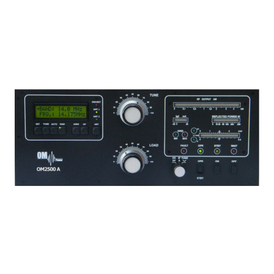
Page 13: Operation Elements
CAUTION Do not turn PA on for at least 2 hours after unpacking it and locating in its operating location. Especially when amplifier is moved from a cold place to a warm one because not visible condensation may develop, and this could result in damage to the high voltage circuits of the PA. - Page 14 OPR/STBY „OPERATE“ sets the amplifier ready for transmit operation. In STBY, if WAIT-LED is on or the amplifier is OFF, the amplifier is in bypass-mode and your transceiver is directly connected to the antenna. Maximum allowed power in bypass mode is 400 Watts! RF OUTPUT Bar graph –...
-
Page 15: Configuration Of Power Amplifier
TUNE Push button for selection of TUNE mode AUTO Push button for selection of AUTOmatic mode Push button for selection of MANUAL mode DWN / UP Push button for selection of band, segment or parameter 5.2. Configuration of Power Amplifier When the ON button is pressed the amplifier will start to heat the final amplifier tube. -
Page 16: Connection With No Supported Tcvrs
Confirm CHOOSE TCVR by pressing SET again and scroll UP / DWN to your transceiver type. Confirm the selection by pressing SET Continue by selecting Baud Rate. Press SET button and scroll using UP / DWN to BAUD RATE. Press SET again. Baud rate for TCVR –... -
Page 17: Communication Loss
Example of communication 5.2.3. Communication loss If TCVR is not connected or communication settings are incorrect the message “COMMUNICATION LOST” will be displayed. You can still use PA by entering MANUAL mode (MAN Button) or by correcting the transceiver connection problem. Example of Communication loss message 5.2.4. -
Page 18: Bandpass Filter Settings
Then select how many antennas you want per current band (1 or 2) and always confirm your selection by pressing SET. The by scrolling UP / DWN you assign which PORT is used on your external antennas switch for this particular antennas. (ANT 1 ON PORT 01) Shall you decide to use 2 antennas for this band then after confirming that with SET configuration continue to the other antenna selection / port selection. -
Page 19: Mute Option
Then select if you want to erase all settings (pressing TUNE) or just one setting value (SET button). In the case of resetting a single parameter use UP / DWN to select which option and confirm by SET. 5.2.7. MUTE option When operating the OM2500A with an Icom transceiver without TX INHIBIT for disabling TX, we recommend blocking of the TX while tuning using ALC control (mainly while operating FM /RTTY/ AM). -
Page 20: Lcd Settings Menu
5.2.8. LCD Settings Menu By pressing SET and scrolling UP / DWN and selecting LCD CONTRAST (Confirming by SET) and pressing Up or DWN you can vary the Contrast of the LCD display. Press SET for confirm the setting. 5.2.9. Operation in MANUAL mode To enter Manual mode of the PA please press MAN. -
Page 21: Auto Or Manual
CAUTION The grid-current is shown with 2 LED diodes. It’s normal if the green LED is flashing or may be shining a little bit during peak operation. If you overload the amplifier the output power increases the grid current at very small rates and the red GRID-MAX- LED is shining and the safety devices switch the PA to STBY. - Page 22 CAUTION After switching on, please confirm that the blower is operating properly. Air must be flowing from the ventilating aperture above the tube. If there is any concern, or no air flow, press the “OFF” button immediately! Heating of the tube takes about 150 seconds. After this time the WAIT LED goes out and the amplifier is ready for operation.
-
Page 23: Tuning Adjustment
CAUTION Should the amplifier demonstrate any malfunctions during tuning or should it not behave in accordance witch the description, interrupt the tuning procedure immediately and check the amplifier! Be sure to have not done any mistakes in choosing bands or TUNE/LOAD values! Be sure that VSWR is not higher than 2:1 and input power is LOW! After excluding possible human mistakes you will be able to work for long time with this... -
Page 24: Maintenance
HV + IP - tuning fault, incorrect tuning of the Pi-L output circuit In case your OM2500A amplifier is not working correctly, please contact the manufacturer or your dealer. Manufacturer’s contacts: OM POWER, s.r.o. 930 30 Báč 126 SLOVAKIA Email: om-power@om-power.com... -
Page 25: Fuse Replacement
6.2. Fuse Replacemeent The user is allowed to change mains fuses (6,3 x 32mm), accesible from the rear panel, only. In the case of interrupted fuse (fuses) inside the power amplifier, contact your dealer, please. 6.3. Tube Replacement In the case of vacuum tube damaging, contact the manufacturer or your dealer for ordering new one. -
Page 26: Appendix
APPENDIX 7.1. Example of connection for Icom... -
Page 27: Example Of Connection For Elecraft
7.2. Example of connection for ELECRAFT... -
Page 28: Example Of Connection With Yaesu
7.3. Example of connection with Yeasu... -
Page 29: Example Of Connection With Antenna Switch And Bpf
7.4. Example of connection with antenna switch and BPF... -
Page 30: Example Of Connection Usb Micro Keyer
7.5. Example of connection USB micro KEYER II with IC7800 or IC7700... -
Page 31: Example Of Connection Usb Micro Keyer Ii With Another Icom
7.6. Example of connection USB micro KEYER II with another Icom... -
Page 32: Example For Connection Usb Micro Keyer
7.7. Example for connection USB micro KEYER II with Yeasu or ELECRAFT... -
Page 33: Example Of Connection Pa With Microham Mkii, (Mk2R+ Etc ) With Ci-V Output
7.8. Example of connection PA with MicroHAM MKII, (MK2R+ etc ) with CI-V output... -
Page 34: Block Diagram Of Om2500A Power Amplifier (Usa Version)
Block Diagram of the OM2500A Power Amplifier...
Need help?
Do you have a question about the OM2500 A and is the answer not in the manual?
Questions and answers