Table of Contents
Advertisement
Quick Links
SIMATIC NET
Communications Processor
for Industrial Ethernet and
Technical Manual
03/2003
J31069-D0429-U001-A0-7618
Foreword
List of Figures
List of Tables
Introduction
Installation and Comissioning
Configuration
Programming
Diagnosis
Appendix A: Technical Data
back
Advertisement
Table of Contents

Related Manuals for Siemens SIMATIC NET CP 243-1 IT


Summary of Contents for Siemens SIMATIC NET CP 243-1 IT
-
Page 1: Table Of Contents
back Foreword Product Information Table of Contents List of Figures List of Tables Introduction Features and Functions SIMATIC NET Installation and Comissioning CP 243-1 IT Configuration Communications Processor Programming for Industrial Ethernet and Information Technology Diagnosis Appendix A: Technical Data Appendix B: Example Technical Manual Appendix C: Timeouts... -
Page 2: J31069-D0429-U001-A0
Copyright © Siemens AG 2003 All rights reserved Exclusion of liability Passing on and reproduction of this document, or utilization and Although we have checked the contents of this publication for revelation of its contents is prohibited without express permission. - Page 3 Brands SIMATIC , SIMATIC NET , SINEC and SIMATIC NET Networking for Industry ® are registered brands of Siemens AG. The other designations in this publication may be brands whose use by third par- ties for their own purposes may violate the rights of the owners.
- Page 4 Caution The device may only be used for the technical applications described in the cata- log and only with products of Siemens or recommended by Siemens or devices and components of other manufacturers which have been approved by Siemens. Correct, safe operation of the product depends on correct transportation, correct storage, installation and mounting as well as careful operator control and mainte- nance.
-
Page 5: Foreword
03/03 Foreword Foreword Purpose of this manual This manual will be helpful when you use your CP 243-1 IT communications proc- essor. It provides you with information on how to communicate with this communi- cations processor via Industrial Ethernet and how to use the Information Technol- ogy functions. -
Page 6: Product Information
Product Information 03/03 Product Information Address label: MAC address The CP 243-1 IT is delivered with a permanently set MAC address. This MAC ad- dress is shown on a label underneath the upper covering flap of the device. MLFB number, scope of delivery Product Name MLFB Scope of Delivery... -
Page 7: Table Of Contents
03/03 Table of Contents Table of Contents Foreword ......................5 Product Information ..................6 List of Figures....................10 List of Tables ....................11 Introduction .................... 13 Features and Functions................. 15 Overview ......................15 S7 Communication via Industrial Ethernet............17 2.2.1 Preliminary Comments.................. - Page 8 Table of Contents 03/03 Demounting the CP 243-1 IT ................54 Configuration..................55 Possible Configurations ..................55 Value Ranges of the Configuration Data ............57 4.2.1 IP Addresses...................... 57 4.2.2 Subnet Mask ...................... 57 4.2.3 TSAPs ........................ 57 4.2.4 Ports ........................58 4.2.5 E-Mail Tags ......................
- Page 9 03/03 Table of Contents Appendix A Technical Data ..............121 Appendix B Example ................. 123 Appendix C Timeouts................131 Abbreviations....................133 CP 243-1 IT J31069-D0429-U001-A0-7618...
-
Page 10: List Of Figures
List of Figures 09/02 List of Figures Fig. 1 System overview ..................... 19 Fig. 2 Overview of the IT functions..................23 Fig. 3 Connections ......................43 Fig. 4 Front with the LEDs....................44 Fig. 5 Space requirements during installation ..............49 Fig. -
Page 11: List Of Tables
03/03 List of Tables List of Tables Table 1 Predefined HTML pages ..................36 Table 2 Directory structure of the CP 243-1 IT ..............38 Table 3 Length of the user names and passwords .............. 40 Table 4 Function of the individual LEDs................45 Table 5 Examples of formatting instructions for placeholders in e-mails...... - Page 12 List of Tables 03/03 Table 27 Addressing of global errors and module information ..........108 Table 28 Layout of the NPB memory area................109 Table 29 Error messages in byte format ................115 Table 30 Error messages in word format ................118 Table 31 Error messages for test routine for e-mails ............
-
Page 13: Introduction
03/03 Introduction Introduction Definition and application The CP 243-1 IT is a communications processor designed for use in an S7-200 programmable controller. It permits an S7-200 system to be connected to Industrial Ethernet (IE). This makes communication via Ethernet possible even in the lower performance class of the S7 product family. - Page 14 Introduction 03/03 Caution Only one CP 243-1 or one CP 243-1 IT may be connected per S7-200 CPU. If ad- ditional CP 243-1 or CP 243-1 IT processors are connected, the S7-200 system may no longer function correctly. The software of the CP 243-1 IT is compatible with the following standards. •...
-
Page 15: Features And Functions
03/03 Features and Functions Features and Functions Overview The CP 243-1 IT offers the following functions. • S7 communication − Performance data communication via Industrial Ethernet. Communication is based on standard TCP/IP. − Ethernet access via RJ45 socket − Easy connection to an S7-200 system via the S7-200 backplane bus −... - Page 16 Features and Functions 03/03 − Storage of own HTML pages and Java Applets in the file system of the CP 243-1 IT − Provision of Java Applets and Beans for development of own HTML pages and Java Applets − User administration for up to 8 users with user-specific granting of rights for access to files, status information and process variables.
-
Page 17: S7 Communication Via Industrial Ethernet
03/03 Features and Functions S7 Communication via Industrial Ethernet 2.2.1 Preliminary Comments S7 communication via Industrial Ethernet permits program-controlled communica- tion via communication SFBs/FBs and configured S7 connections. The CP 243-1 IT supports S7 communication via Industrial Ethernet with the XPUT/XGET and READ/WRITE services. -
Page 18: Types Of Communication
Features and Functions 03/03 2.2.2 Types of Communication The CP 243-1 IT has three types of S7 communication relationships which can be used individually and in combination. 1. Coupling with STEP 7-Micro/WIN 32 2. Coupling with other, geographically remote components of the SIMATIC S7 family 3. -
Page 19: Fig. 1 System Overview
03/03 Features and Functions Overview S7-200 Micro/WIN BOOTP- Server max. 8 x xput / xget read / write Ethernet OPC-Server OPC-Client S7-200 S7-300 S7-400 Fig. 1 System overview A CPU 22x with CP 243-1 IT can communicate both with other S7-200, S7-300 and S7-400 systems and with an OPC server. - Page 20 Features and Functions 03/03 Data communication via Industrial Ethernet Data communication via the CP 243-1 IT is based on Ethernet and is thus not de- terministic (i.e., specific response times are not guaranteed). 10 and 100-Mbit net- works are supported in full and half-duplex. In addition, the CP 243-1 IT supports the auto-negotiation function for automatically negotiating the operating mode and the transmission speed to be used.
- Page 21 03/03 Features and Functions S7 communication The XPUT and XGET S7 services are used to communicate data between two controllers. The CP 243-1 IT can be used both as client and as server. Communication between a CP 243-1 IT and an OPC server running on a PC/PG uses the READ and WRITE S7 services.
- Page 22 Features and Functions 03/03 Backplane bus communication All accesses to all data areas of the S7-200 CPU are always possible. The read and write accesses are not dependent on whether the CPU is in RUN, TERM or STOP status. CP 243-1 IT J31069-D0429-U001-A0-7618...
-
Page 23: It Communication
03/03 Features and Functions IT Communication 2.3.1 Preliminary Remarks In addition to S7 communication via Industrial Ethernet, the CP 243-1 IT also sup- ports the services XPUT/XGET and READ/WRITE parallel to a variety of IT func- tions. These include data communication via FTP, sending e-mails, and the capa- bility of permitting up to four Web browsers to access data and status information on the S7-200 system at the same time. -
Page 24: Types Of Communication
Features and Functions 03/03 2.3.2 Types of Communication In addition to the S7 communication relationships described in chapter 2.2.2, the CP 243-1 IT offers four types of IT communication relationships which can be used individually or in combination. 1. Communication with an e-mail server 2. -
Page 25: E-Mail
03/03 Features and Functions 2.3.3 E-Mail How it works The SMTP protocol controls the transmission of e-mails. An e-mail consists of one or two address fields, a subject field and a field for the actual text message. The text message consists of ASCII characters. The text may contain placeholders for variables which reference a data value of the local S7-200 system. - Page 26 Features and Functions 03/03 Note Before e-mails can be sent from the CP 243-1 IT, you must make sure that a func- tioning e-mail server can be accessed from there. General accessibility of an e-mail server can be tested with the HTML page "sendmail.htm,"...
-
Page 27: Ftp Server
03/03 Features and Functions Note The maximum length of the e-mail text of 1024 characters refers to the actual mes- sage text including all embedded placeholders and all format characters ("\n" and "\t"). If the maximum permissible length of 1024 characters is exceeded by resolution of the placeholders when an e-mail is sent, the e-mail text is truncated after 1024 characters and an appropriate error message is returned. - Page 28 Features and Functions 03/03 All types of files can be transferred to the file system of the CP 243-1 IT. Rele- vance of these files to operation of the CP 243-1 IT is not checked. Caution BINARY-type transmission should be used to transfer files between the FTP server of the CP 243-1 IT and a geographically remote FTP client.
-
Page 29: Ftp Client
03/03 Features and Functions Supported FTP commands After the HELP command is entered in the console box of the FTP client, a list of the FTP commands supported by this client usually appears. While these com- mands are being executed, they can then be converted internally by the FTP client into subcommands and sent to the FTP server. - Page 30 Features and Functions 03/03 With the help of the FTP client, it is possible to delete files in the file system of an FTP server from the local S7-200 system. During the transmission with FTP, the files to be exchanged are not changed and the data therein are not converted.
- Page 31 03/03 Features and Functions − Start address and length of the data in the data block Specify here the address starting at which the data to be read are to be stored in the memory of the S7-200 CPU or the address starting from which the data to be written are to be sent to the FTP server, and how many bytes are to be transmitted.
- Page 32 Features and Functions 03/03 To ensure consistency with large amounts of data, appropriate measures must be provided in the S7-200 application program. When a transmission between the FTP client of the CP 243-1 IT and an FTP server is interrupted, only part of the transferred data may have been stored on the destination system.
-
Page 33: Http Server
03/03 Features and Functions 2.3.6 HTTP Server Fundamentals Java Applets are little application programs prepared in the programming language Java. At a browser's request, such Applets are usually transferred from an HTTP server to a browser and executed there. The browser must have Java capability and must permit execution of Applets. - Page 34 Features and Functions 03/03 Note The availability of the data types CHAR, INT, DINT and REAL depends on the firmware status of the S7-200 CPU being used. Access protection Calling the HTML pages stored in the file system of the CP 243.1 IT with a Web browser is not subject to access protection.
- Page 35 03/03 Features and Functions HTML Page Call Meaning http://<destination IP address>/index.htm Start page of the CP 243-1 IT with links to further in- ternal and external HTML pages If only <destination IP address> is specified on the Web browser, index.htm is automatically opened. http://<destination IP address>/__S7Sys/rack Indicates the setup of the S7-200 destination system.
-
Page 36: Table 1 Predefined Html
Features and Functions 03/03 HTML Page Call Meaning http://<destination IP ad- General information page of the CP 243-1 IT with ex- dress>/examples/info.htm ternal links to the IT CP and SIMATIC NET Web page. An internal link refers to the Web page readme.htm. http://<destination IP ad- This page can be used to read process values of the dress>/examples/statuschart.htm... -
Page 37: File System
03/03 Features and Functions File System How it works A file system is available on the CP 243-1 IT to permanently store Web and con- figuration files. This file system uses flash memory technology and offers a storage capacity of 8 Mbytes minus the memory needed for administration of the flash file system. -
Page 38: Table 2 Directory Structure Of The Cp 243-1 It
Features and Functions 03/03 Restrictions Caution The life of a file system based on flash memory technology is primarily determined by the number of write or deletion operations performed on it. Obviously such a file system is not suited to highly cyclic write or delete operations. The file system of the CP 243-1 IT uses an internal optimization routine to assign all available locations of the flash memory uniformly. -
Page 39: User Administration
03/03 Features and Functions User Administration How it works When process data are exchanged via Intranet/Internet services, security becomes very important. To ensure security, user administration with graduated password protection was in- tegrated on the CP 243-1 IT. Up to 8 users can be configured with the Internet wiz- ard of STEP 7 Micro/WIN 32. -
Page 40: Table 3 Length Of The User Names And Passwords
Features and Functions 03/03 The following user rights can be configured for the 8 other users. • Read access to process data of the S7-200 system from a Web browser • Read and write access to process data of the S7-200 system from a Web browser •... -
Page 41: Security
03/03 Features and Functions Security 2.6.1 Configuration Part of the configuration of the CP 243-1 IT is retentively stored on the S7-200 CPU and part in the file system of the CP 243-1 IT. The validity of the portion of the configuration stored on the S7-200 CPU is secured by a CRC routine. -
Page 42: Information Technology
Additional information on the subject of security can be found in the document on information technology for the Siemens AG automation technology. The CP 243-1 IT disconnects an active STEP 7 Micro/WIN 32 connection when no STEP 7 Micro/WIN job was sent to the CPU during the last 50 seconds. -
Page 43: Connections
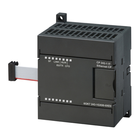
03/03 Features and Functions Connections Front view Fig. 3 Connections The CP 243-1 IT is equipped with the following connections. • Terminal block for 24 V DC power and grounding connection • 8-pin RJ45 socket for Ethernet connection • Pin plug connector for backplane bus •... -
Page 44: Indicators: Front Leds
Features and Functions 03/03 Indicators: Front LEDs Fig. 4 Front with the LEDs There are 5 LED indicators on the front. LED Indicator Color Meaning System error: Red, continuously On when an error has occurred System error: Red, flashing Flashing (approx. once per second) when configura- tion is incorrect or no BOOTP server could be found Connection via the RJ45 interface: LINK... -
Page 45: Table 4 Function Of The Individual Leds
03/03 Features and Functions LED Indicator Color Meaning ously on The CP 243-1 IT is ready for communication. Configuration: Yellow, continu- Is on when STEP 7 Micro/WIN 32 actively maintains ously on a connection to the S7-200 CPU via the CP 243-1 Table 4 Function of the individual LEDs During the startup phase of the CP 243-1 IT, the SF LED flashes twice. - Page 46 Installation and Commissioning 03/03 CP 243-1 IT J31069-D0429-U001-A0-7618...
-
Page 47: Installation And Commissioning
03/03 Installation and Commissioning Installation and Commissioning Installation You can install the devices of the S7-200 family either in an operator panel or on a DIN rail. You can arrange the modules both horizontally and vertically. The S7-200 CPU and the expansion modules are designed for natural heat dissipation via con- vection. -
Page 48: General Guidelines
Installation and Commissioning 03/03 General guidelines Below are some general guidelines for wiring your programmable controller. • Be sure to comply with all valid and binding standards when you wire your CP 243-1 IT. When installing and operating the device, adhere to applicable na- tional and regional regulations. -
Page 49: Fig. 5 Space Requirements During Installation
03/03 Installation and Commissioning Space requirements during installation When installing your module, adhere to the following guidelines. • The CP 243-1 IT is designed for natural heat dissipation by convection. For this reason, leave at least 25 mm of free space above and below the device so that the heat is free to escape. -
Page 50: Cp 243-1 It
Installation and Commissioning 03/03 Dimensions for Installation in a Control Panel The CP 243-1 IT is equipped with bored holes for installation in a control panel. 96 mm 88 mm CP 243-1 IT 80 mm 63.2 mm Minimum distance of 9.5 mm between the modules when 71.2 mm installed in the switching... -
Page 51: Installation In A Control Panel
03/03 Installation and Commissioning Installation in a Control Panel What to do/steps 1. Bore holes for the DIN M4 screws on the control panel. Read and follow the notes and dimensions given in chapters 3 and 3.1 on installation in a control panel. -
Page 52: Installation On A Standard Din Rail
Installation and Commissioning 03/03 Installation on a Standard DIN Rail What to do/steps 1. Open the snap catch and hang in the CP 243-1 IT on the DIN rail to the right next to or above the CPU. 2. Close the snap catch to secure the CP 243-1 IT to the rail. Make sure that the catch is snapped in correctly and the device is firmly secured to the rail. -
Page 53: Replacement Parts
03/03 Installation and Commissioning Replacement Parts When the CP 243-1 IT (6GK7 243-1GX00-0XE0) module is replaced, no new pro- gramming is required on the S7 communication side since configuration data and the user program are stored retentively on the S7-200 CPU. The CP 243-1 IT must be programmed again for the IT functions since the configuration files, among oth- ers, for the IT services are stored in the file system of the CP 243-1 IT. -
Page 54: Demounting The Cp 243-1 It
Installation and Commissioning 03/03 Demounting the CP 243-1 IT Warning If you attempt to install or remove the CP 243-1 IT or other devices while they are on, you may receive an electric shock or the devices may not work properly. If the power is not switched off for the CP 243-1 IT and all connected devices while the devices are being installed/removed, this may cause injury and/or property damage. -
Page 55: Configuration
03/03 Configuration Configuration Possible Configurations Using the CP 243-1 IT, an S7-200 system can communicate via the S7 protocol with both another S7-200 system and an S7-300 or S7-400 or an OPC-based sys- tem. Using the IT protocols SMTP, FTP and HTTP, communication is also possible with any computer system which supports this protocol. - Page 56 Configuration 03/03 The TCP/IP address parameters (IP address, subnet mask, IP address of a gate- way) can be specified during configuration in one of two ways. They can be speci- fied permanently or dynamically (the CP 243-1 IT takes the TCP/IP address pa- rameters from a BOOTP server during startup).
-
Page 57: Value Ranges Of The Configuration Data
03/03 Configuration Value Ranges of the Configuration Data 4.2.1 IP Addresses The IP addresses which must be specified at various points in the configuration must comply with the general conventions governing the validity of IP addresses. According to this convention, the following IP addresses have a special signifi- cance. -
Page 58: Ports
Configuration 03/03 4.2.4 Ports Each standard protocol from the TCP/IP protocol family (e.g., HTTP, FTP or SMTP) is assigned its own fixed port number with which a related communication service can usually be accessed in a TCP/IP network. These permanently as- signed port numbers are called "known"... -
Page 59: Table 5 Examples Of Formatting Instructions For Placeholders In E-Mails
03/03 Configuration The element "positions_before_decimal" defines the minimum number of digits which may be indicated to the left of the decimal point. This value should be large enough to hold the expected data value including a sign if necessary. If the number of positions specified in the element "positions_before_decimal" is not sufficient to completely indicate a current value, this value is still presented completely. -
Page 60: Configuration Of A Cp 243-1 It With Step 7 Micro/Win 32
Configuration 03/03 Note Whole numbers with sign (format element) and whole numbers without sign (format element U) can be interpreted as fixed point decimal numbers. Example: VD 100 contains the fixed point number for the to-be-interpreted value 12345 If the placeholder %VD100:2.3U% is used for this value in an e-mail, this value is transmitted in the e-mail as 12.345. -
Page 61: Basic Configurations
03/03 Configuration Note For detailed information, see the STEP 7 Micro/WIN 32 documentation included with the STEP 7 Micro/WIN 32. 4.3.1 Basic Configurations After starting the Internet wizard, you will see the configuration wizards. All specifi- cations which you enter here will be stored on the S7-200 CPU when loaded to the S7-200 system. - Page 62 Configuration 03/03 This screen is used to specify how many S7 connections are to be set up on your CP 243-1 IT. Up to 8 such connections are possible. A screen appears for each connection that you specify here. You can then configure the connection with this screen.
- Page 63 03/03 Configuration Activating/deactivating the CRC routine and specifying the monitoring time After you have finished configuring the S7 connection, you must specify in the next screen whether your configuration data on the S7-200 CPU are to be protected with a CRC routine against accidental overwriting. If the CRC routine is activated, the CP 243-1 IT checks during startup to determine whether its configuration data which it reads from the memory of the S7-200 CPU were overwritten from the user program.
- Page 64 Configuration 03/03 Setting up an administrator The next screen is used to specify the user identifier and the password for the ad- ministrator. You also specify whether the administrator will have the right to access the process data of the S7-200 system with a Web browser. Activating the individual IT services The next screen can be used to activate various IT services of the CP 243-1 IT in- dividually.
-
Page 65: Configuration Of User Administration
03/03 Configuration 4.3.2 Configuration of User Administration To branch to the wizard to configure user administration, click the appropriate icon in the left-hand box of the screen. All the information entered in this wizard is stored in the file system of the CP 243-1 IT in a file with the ending .udb when the configuration is loaded to the S7-200 system. -
Page 66: Configuration Of The Ftp Functions
Configuration 03/03 Placeholders for data from the S7-200 system can be inserted in the actual e-mail text to be sent. When the e-mail is sent, the CP 243-1 IT replaces each of these placeholders with the current value of the data. To insert such a placeholder in your e-mail, click "Insert Data". -
Page 67: Conclusion Of Configuration
03/03 Configuration For each FTP job, you must specify the FTP server to which the job is to be sent and the name of the file which is to be processed by the job. For this, enter the IP address of the FTP server and the name of the file including any required path in- formation. - Page 68 Configuration 03/03 Access to the configuration data in the memory of the CPU The configuration data stored in the memory of the S7-200 CPU can also be changed directly from an S7-200 user program. Before the CP 243-1 IT can accept configuration data which have been changed like this when it boots again, the CRC protective routine for configuration data must be disabled.
-
Page 69: Assigned System Marker Area (Sm Area)
03/03 Configuration 4.4.1 Assigned System Marker Area (SM Area) The CP 243-1 IT occupies 50 bytes in the system marker area of the S7-200 CPU. The address of these 50 bytes depends on the current position a CP 243-1 IT oc- cupies in an S7-200 system. -
Page 70: Structure Of Configuration Data Block (Cdb)
Configuration 03/03 4.4.2 Structure of Configuration Data Block (CDB) The CDB is created by the Internet wizard in STEP 7 Micro/WIN 32. The structure of the CDB is shown below in the following table. Byte Offset Description Data Format Example in Variable Memory Header... - Page 71 03/03 Configuration Byte Offset Description Data Format Example in Variable Memory 16#00000000 when BOOTP is being used. 23-26 IP address of the gateway 4 bytes, hex 192.12.45.24: 16#00000000 means: Don't use 16#C00C2D18 gateway. This field should be set to 16#00000000 when BOOTP is being used.
- Page 72 Configuration 03/03 Byte Offset Description Data Format Example in Variable Memory S7 connection 2 section (If not all bytes of this section are used, fill them with16#00.) Flag byte 1 byte, hex See S7 connection 0 section. See S7 connection 0 section. 48-49 IP address of the partner 4 bytes, hex...
-
Page 73: Table 7 Structure Of The Cdb
03/03 Configuration Byte Offset Description Data Format Example in Variable Memory 88-89 Local TSAP 2 bytes, hex 16#1600 90-91 Remote TSAP 2 bytes, hex See S7 connection 0 section. S7 connection 7 section (If not all bytes of this section are used, fill them with16#00.) Flag byte 1 byte, hex See S7 connection 0... -
Page 74: Structure Of The Network Parameter Block (Npb)
Configuration 03/03 4.4.3 Structure of the Network Parameter Block (NPB) The CP 243-1 IT creates this data block automatically based on the current record of the network parameters. It contains the currently used TCP/IP parameter values if the CP 243-1 IT was configured correctly. If configuration errors occurred, the NPB does not contain valid entries. - Page 75 03/03 Configuration The structure of the NDB is shown in the following table. The identifiers for read/write jobs are represented by the letters n, m, p = 0, ..., 31 and the channel identifiers with the letters r = 0, ...,7. Byte Offset in Name Description...
-
Page 76: Structure Of The Internet Data Block (Idb)
Configuration 03/03 Byte Offset in Name Description Data Variable Memory Format ASCII COM_CHr_p ASCII CRC section The last two bytes CRC for all NDB 2 bytes, hex The last two of the NDB bytes without the bytes of the CRC section itself Table 9 Structure of the NDB Name... - Page 77 03/03 Configuration Byte Offset Description Data Format Example in Variable Memory Header Length of the IDB 2 bytes, hex 16#43 = 67 bytes (with CRC) Length of the general section 1 byte, hex 16#32 = 50 bytes Length of the SMTP client section 1 byte, hex 16#02 = 2 bytes Length of the FTP client section...
-
Page 78: Table 11 Structure Of The Idb
Configuration 03/03 Byte Offset Description Data Format Example in Variable Memory FTP client section 59 - 60 FTP client flag 2 bytes, hex 16#0001 Bit [0] Enable bit FTP client enabled 0: Disabled 1: Enabled Bit [1] - [15] Reserved FTP server section 61 - 62 FTP server flag... -
Page 79: Structure Of The Configuration File For User Administration (.Udb File)
03/03 Configuration 4.4.6 Structure of the Configuration File for User Administration (.udb File) The configuration file for the user administration is created by the Internet wizard in STEP 7 Micro/WIN 32 and stored in a file with the ending .udb. The structure of this file is shown in the following table. -
Page 80: Table 13 Structure Of The Parameter Record Of A User
Configuration 03/03 Parameter Description Example Access rights The access rights are represented in 00|00010048|<User name>|<Password> - Read and write access via HTTP hexadecimal format. Bit [0-1] Not used - Access to status page of the CP 243-1 IT via HTTP server Bit [2] Read access to data of the S7- 200 CPU via the HTTP server - Access to all FTP functions... - Page 81 03/03 Configuration Example of a user configuration file # This is a comment TIMESTAMP=3D2C4E48 FILETYPE=UDB FILEFORMAT=01 00|00010048|Benutzer_mit_allen_Rechten|C~WB1" 01|00000040|Status_CP|UX3MUppLjRzn*R 02|00010000|FTP_Zugriff|W9vQ}G cfH 03|00000000|| 04|00000000|| 05|00000000|| 06|00000000|| 07|00000000|| # End of File Note − Commentary is added to the file with the # character. −...
-
Page 82: Appendix B: Example
Configuration 03/03 4.4.7 Structure of the Configuration File for the E-Mail Client (.edb File) The configuration file for the e-mail client is created by the Internet wizard in STEP 7 Micro/WIN 32 and stored in a file with the ending .edb. The table below shows the structure of this file. -
Page 83: Table 14 Structure Of The Configuration File For The E-Mail Client
03/03 Configuration Key Word in Description Example the .edb File 01|TX| Text 01|TX|This is a \n\t text with formatting. E-mail 31(identification of the 32 possible e-mails with 00, 01, 02...30, 31) 31|TO| Recipient address of e-mail 31 31|TO|Name.Name@provider.de 31|CC| Optional recipient address 31|CC|Name.Name@provider.de which is to receive a copy of e-mail 31|SU|... - Page 84 Configuration 03/03 Note − Commentary is added to the file with the # character. − Valid e-mails must have entries in the fields TO, SU and TX. − The last character of a line is \n. − The recipient address TO and CC may not contain more than 64 ASCII characters.
-
Page 85: Structure Of The Configuration File For The Ftp Client (.Fdb File)
03/03 Configuration 4.4.8 Structure of the Configuration File for the FTP Client (.fdb File) The configuration file for the FTP client is created by the Internet wizard in STEP 7 Micro/WIN 32 and stored in a file with the ending .fdb. The structure of this file is shown in the table below. - Page 86 Configuration 03/03 Parameter Description Example Action The FTP client supports the following ac- tions. W: Read the data block or part of the 00|W|<Number of bytes>|<DB start ad- data block and store in a file in bi- dress>|<Path/file name>|<Server ad- nary format.
-
Page 87: Table 16 Structure Of The Parameter Record For An Ftp Job
03/03 Configuration Parameter Description Example Server address Entry of the IP address under which the 00|R|23|VB11| /flash:/dat/CPU10_VB11_23.dat 192.168.162.65|<User name>| <Pass- FTP server can be accessed word> The file /flash:/dat/CPU10_VB11_23.dat transferred from the file system of the FTP server which can be accessed via IP address 192.168.162.65 (stating <User name>... - Page 88 Configuration 03/03 Example of an FTP client configuration file # This is a comment TIMESTAMP=3D2C4E48 FILETYPE=FDB FILEFORMAT=01 00|W|1|VB0|station99_VB0_1.dump|192.168.232.13|FTP_Server_2|3AqW&4Cv 01|W|1024|VB256|/station36_VB256_1024.data|192.168.232.13|FTP_Server_2|3AqW&4Cv 02|R|5|VB2|/data/station36_VB2_5.err|192.168.232.2|FTP_Server_3|asw345Df 03|R|23|VB11|/flash:/dat/CPU10_VB11_23.dat|192.168.162.65| FTP_Server_4| W9vQ}G cfH 04||||||| 05||||||| 06||||||| 07|D|||/data/station36_VB2_5.err|192.168.232.2|FTP_Server_3|asw345Df 08||||||| ..30||||||| 31||||||| # End of File Note − Commentary is added to the file with the # character. −...
-
Page 89: Configuration Of A Communication Partner With Step 7
03/03 Configuration Configuration of a Communication Partner with STEP 7 Using the example of an S7-300 system, this chapter describes the configuration steps that must be performed in STEP 7 so that such a system is able to communi- cate with an S7-200 system via the related Ethernet communications processor. The procedure is similar for S7-400 systems. -
Page 90: Fig. 8 Screen "Properties – S7 Connection
Configuration 03/03 Configured connections If you want to use a configured connection, first insert a new S7 connection in the STEP 7 program packet NetPro. In the screen "Insert new connection," specify the type of station with which you want to establish a connection. As connection part- ner, select the type "unspecified."... - Page 91 03/03 Configuration In the screen "Adress details," specify the communication access points ("TSAPs") to be used. You will find the TSAP of a connection in the S7-200 system in STEP 7 Micro/WIN 32 in the screen in which you configured the individual connections un- der the entry "Local Properties."...
- Page 92 Configuration 03/03 Free connections A free connection can only be used when your S7-300 or S7-400 system is to be the server. Free connections do not have to be configured in STEP 7. Standard S7-300 and S7-400 systems are designed so that they can communicate via free connections.
-
Page 93: Reaction Of The Cp 243-1 It To Configuration Errors
03/03 Configuration Reaction of the CP 243-1 IT to Configuration Errors When the CP 243-1 IT detects an invalid configuration, it tries to obtain its TCP/IP address parameters (IP address, subnet mask and IP address of the gateway) via a BOOTP service. The CP 243-1 IT continues to attempt this for approx. 1 minute. When it fails to receive a reply from a BOOTP service within this time or the reply is invalid or has errors, the red LED ("SF") flashes for approx. - Page 94 Programming 03/03 CP 243-1 IT J31069-D0429-U001-A0-7618...
-
Page 95: Programming
03/03 Programming Programming Use STEP 7 Micro/WIN 32 to develop S7-200 user programs. The version STEP 7 Micro/WIN 32 must be V3.2.3 or higher so that you can use the functions of the CP 243-1 IT in these programs. To be able to use the CP 243-1 IT as an S7, e-mail or FTP client, at least one of the communication channels of the CP 243-1 IT must be configured appropriately. -
Page 96: Ethx_Ctrl
Programming 03/03 ETHx_CTRL The subprogram ETHx_CTRL initializes and monitors the CP 243-1 IT. You must call this subprogram in your S7-200 user program at the beginning of every cycle if you want to utilize the functions of a CP 243-1 IT. After a iser program or a new configuration is downloaded by SETP 7 Micro/Win 32 to the S7-200 CPU and the S7-200 CPU is started again, this subroutine commands the Cp 243-1 IT to check for changes in the configuration data. -
Page 97: Table 18 Return Parameters (Ethx_Ctrl)
03/03 Programming Return parameters: Name Type Meaning CP_Ready BOOL Status of the CP 243-1 IT CP not ready CP ready CH_Ready WORD Status of the individual channels or IT services Bit 0 corresponds to e-mail service Bit 1 corresponds to FTP client service Bit 2 corresponds to FTP server service Bit 3 corresponds to HTTP server service Bit 4 –... -
Page 98: Ethx_Cfg
Programming 03/03 ETHx_CFG Calling the subprogram ETHx_CFG causes the CP 243-1 IT to read in the configu- ration data which are stored in the memory of the S7-200 CPU. The CP 243-1 IT then automatically performs a reset after the subprogram ETHx_CFG is called. The configuration read from the memory of the S7-200 CPU takes effect after the re- start following the reset. -
Page 99: Ethx_Xfr
03/03 Programming Return parameters: Name Type Meaning Done BOOL Status of the subprogram call Subprogram not executed yet Subprogram executed, ready for next execution Error BYTE Error code 16#00: No error Other: Error (for a description, see chapter 6.2) Table 20 Return parameters (ETHx_CFG) ETHx_XFR Calling the subprogram ETHx_XFR causes the CP 243-1 IT to transfer data to an-... -
Page 100: Table 21 Input Parameters (Ethx_Xfr)
Programming 03/03 Call: ETHx_XFR Always_On START_BIT START CHANNEL Done Chan_ID DONE DATA Error Data ABORT Abort Fig. 11 Call of the subprogram ETHx_XFR Input parameters: Name Type Meaning START BOOL Input condition for triggering a read/write job Don't trigger read/write job Trigger read/write job Chan_ID BYTE... -
Page 101: Ethx_Email
03/03 Programming Return parameters: Name Type Meaning Done BOOL Status of the subprogram call Subprogram not executed yet Subprogram executed, read/write job concluded, subprogram ready for next Error BYTE Error code 16#00: No error Other: Error (for a description, see chapter 6.2) Table 22 Return parameters (ETHx_XFR) -
Page 102: Table 23 Input Parameters (Ethx_Email)
Programming 03/03 Call: ETHx_EMAIL Always_On START START_BIT Done DONE MAIL Error Mail ABORT Abort Fig. 12 Call of the subprogram ETHx_EMAIL Input parameters: Name Type Meaning START BOOL Input condition for triggering an e-mail job Don't trigger e-mail job Trigger e-mail job Mail BYTE Number of the e-mail from the configuration... -
Page 103: Ethx_Ftpc
03/03 Programming Caution E-mail communication is subordinate to S7 communication. Since reaction times vary depending on the particular configuration, no general predictions can be made. The greater the number of simultaneous S7 connections and the larger the amount of data transferred per job, the longer the reaction times will be for an e-mail job. -
Page 104: Table 25 Input Parameters (Ethx_Ftpc)
Programming 03/03 Call: ETHx_FTPC Always_On START START_BIT Done DONE Error ABORT Abort Fig. 13 Call of the subprogram ETHx_FTPC Input parameters: Name Type Meaning START BOOL Input condition for triggering a read/write/delete Don't trigger read/write/delete job Trigger read/write/delete job BYTE FTP client job number from the configuration which describes the read/write/delete job to be executed... -
Page 105: Table 26 Return Parameters (Ethx_Ftpc)
03/03 Programming Return parameters: Name Type Meaning Done BOOL Status of the subprogram call Subprogram not executed yet Subprogram executed, read/write/delete job concluded, subprogram ready for next job. Error BYTE Error code 16#00: No error Other: Error (for a description, see chapter 6.2) Table 26 Return parameters (ETHx_FTPC) - Page 106 Diagnosis 03/03 CP 243-1 IT J31069-D0429-U001-A0-7618...
-
Page 107: Diagnosis
03/03 Diagnosis Diagnosis Diagnostic Capabilities The following aids are available for diagnosis. • Ping server Using the "ping" program which is present on all standard computers with a Windows operating system from Microsoft, you can determine whether a CP 243-1 IT can be always be reached under an IP address to be specified. •... -
Page 108: Table 27 Addressing Of Global Errors And Module Information
Diagnosis 03/03 Byte Offset in Meaning Format SM Area 0-15 Module type 16 bytes, ASCII 16-19 Software version 4 bytes, ASCII 20-21 Error code (see chapter 6.2) 2 bytes, hex Status CP 243-1 IT 1 byte, hex Bit [0] CP 243-1 IT not in startup CP 243-1 IT performing startup Bit [1] BOOTP sequence not performed... -
Page 109: Table 28 Layout Of The Npb Memory Area
03/03 Diagnosis • Reading the NPB memory area A pointer to the memory area in which the configuration data of the CP 243-1 IT are stored is located in bytes 46 to 49 of the SM area currently used for the CP 243-1 IT. - Page 110 Diagnosis 03/03 • Status Applet Using the Web browser, an HTML page can be requested by the CP 243-1 IT indicating the status information of the S7-200 system. This page includes, among others, information on the status of the S7 and IT channels. The call of this page is specified in table 1 together with an overview of the information on this page.
-
Page 111: Error Messages Of The Cp 243-1 It
03/03 Diagnosis Error Messages of the CP 243-1 IT This section lists the error messages of the CP 243-1 which are of primary impor- tance to the user. All other error messages indicate special internal errors of the CP 243-1 IT. If such error messages occur, please contact your service hotline. Caution The module must be turned off and on again when a module error/system error oc- curs. -
Page 112: Error Messages In Byte Format
Diagnosis 03/03 The next few sections list the error codes for the individual errors together with their meaning. Also covered: how the individual errors are returned, which error codes apply to which subprograms, and which error in which byte of the current SM memory area is transferred. - Page 113 03/03 Diagnosis Error Byte Description Reaction/Correction Transfer Rou- tine Byte Return Offset Value in SM (ETHx_) Area 16#05 The connection was terminated or Check connection path to the 25 - 32 _XFR an attempt was made to execute a communication partner or con- read/write job on a channel which figuration of the communication was not ready.
- Page 114 Diagnosis 03/03 Error Byte Description Reaction/Correction Transfer Rou- tine Byte Return Offset Value in SM (ETHx_) Area 16#0B 11 Previous read/write job not yet A new read/write job can be 25 - 32 _XFR concluded triggered. _EMAIL Evaluate "DONE" return pa- _FTPC rameter of the previous read/write job.
-
Page 115: Table 29 Error Messages In Byte Format
03/03 Diagnosis Error Byte Description Reaction/Correction Transfer Rou- tine Byte Return Offset Value in SM (ETHx_) Area 16#19 Error in the FTP transmission pro- Check to determine whether the _FTPC tocol FTP server is configured cor- rectly. Check to determine whether this file can always be ac- cessed. -
Page 116: Error Messages In Word Format
Diagnosis 03/03 6.2.2 Error Messages in Word Format Error Word Description Reaction/Correction Transfer Rou- tine Byte Return Offset Value in SM (ETHx_) Area 16#0001 Time exceeded on the back- Automatic restart 20, 21 _CTRL plane bus 16#000D All data transmissions are ter- New start of the system 20, 21 _CTRL... - Page 117 03/03 Diagnosis Error Word Error Byte Reaction/Correction Transfer Rou- tine Byte Return Offset Value in SM (ETHx_) Area 16#003A The module name for the CP Check the configuration. 20, 21 _CTRL 243-1 IT was changed in the configuration. 16#003B The configuration has an invalid Check the configuration.
-
Page 118: Table 30 Error Messages In Word Format
Diagnosis 03/03 Error Word Error Byte Reaction/Correction Transfer Rou- tine Byte Return Offset Value in SM (ETHx_) Area 16#00B3 The administrator password Prepare configuration with 20, 21 _CTRL check failed or no password STEP 7 Micro/WIN 32. was specified. 16#00B7 The administrator password is Prepare configuration with 20, 21... -
Page 119: Error Messages Of The Test Routine For E-Mails
03/03 Diagnosis Error Messages of the Test Routine for E-Mails The error messages of the test routine for e-mails are indicated on the Web browser as an error code with explanatory text in English. The errors which can occur here are listed in the table below. Error Code Error Text Description... - Page 120 Technical Data 03/03 CP 243-1 IT J31069-D0429-U001-A0-7618...
-
Page 121: Appendix A Technical Data
03/03 Technical Data Appendix A Technical Data Construction S7-200 expansion module • Module format 71.2 x 80 x 62 mm • Dimensions (W x H x D) Approx. 150 g Weight Transmission speed 10 Mbit/sec and 100 Mbit/sec Size of the flash memory 8 Mbytes as ROM for firmware of the CP 243-1 IT and 8 Mbytes as RAM for the file system Size of the SDRAM memory... -
Page 122: Table 32 Technical Data
Technical Data 03/03 Max. e-mail size 1024 characters File system Max. path length incl. file and drive names: 254 characters Max. length of a file name: 99 characters Max. nesting depth of the directory: Server ports used HTTP: FTP command channel: FTP data channels for FTP server: 3100 - 3199 S7 connection establishment:... -
Page 123: Appendix B Example
The configuration (IP address, …) must be adapted to the current conditions. The “CP243” character string must be stored at address VB500 and higher. Copyright: SIEMENS AG, A&D PT2 (c) 2003 NETWORK 1 The ETHT0_CTRL subroutine initializes and monitors the CP 243-1 IT. - Page 124 Example 03/03 Always_On CALL ETH0_CTRL, cp_ready, ch_ready, cp_error Symbol Address Comment SM0.0 Always ON, always 1 Always_On ch_ready cp_error M0.0 cp_ready SBR1 This POU was generated by the Internet wizard for use for the ETH0_CTRL CP243-1 IT. NETWORK 2 As soon as channel 0 is ready for the transmission and "ch0_ready" is set, the variable "start"...
- Page 125 03/03 Example NETWORK 4 The local S7-200 station sends data from the VB500 (data length of 5 Byte) on the Ethernet connection to another S7-200 station. There the data are stored in VB500. The read/write command only takes place after a positive edge at the "START" pa- rameter, if the "Done"...
- Page 126 Example 03/03 Symbol Address Comment SBR2 This POU was generated by the Internet wizard for use with the ETH0_XFR CP243-1 IT. M4.0 Flip flop for automatic start of the data transmission start VB234 Write_1 NETWORK 5 The local S7- 200 station now reads out data from the VB200 of another S7-200 station and stores these in the VB500 of the local S7-200 station.
- Page 127 03/03 Example Data block for this configuration //DATA BLOCK COMMENTS //Press F1 for help and example data block //-------------------------------------------------------------------- // CP243-1 IT Module Configuration block. Generated by the Internet // wizard //-------------------------------------------------------------------- 'CP243' // Module ID for CP243-1 IT module at position 0 16#006C // Length of CDB 16#0014...
- Page 128 Example 03/03 VB83 16#00 // Connection not defined. VD84 16#00000000 VW88 16#0000 VW90 16#0000 //------------------------------------------ Connection 7 VB92 16#00 // Connection not defined. VD93 16#00000000 VW97 16#0000 VW99 16#0000 //----------------------------- STEP 7-Micro/WIN reserved connection. VB101 16#82 VD102 16#00000000 VW106 16#A9A8 //-------------------------------------------------------------------- // Network Parameter Block Section // This section is used by the CP243-1 IT Module...
- Page 129 03/03 Example VW229 16#0000 //HTTP Server enable flag VW231 16#9E28 //-------------------------------------------------------------------- //Symbol Initializations //-------------------------------------------------------------------- VB233 VB234 VB235 //-------------------------------------------------------------------- VB500 'CP243' // Module ID for testing CP 243-1 IT J31069-D0429-U001-A0-7618...
- Page 130 Example 03/03 CP 243-1 IT J31069-D0429-U001-A0-7618...
-
Page 131: Appendix C: Timeouts
03/03 Timeouts Appendix C Timeouts The values in the following tables represent times which must pass before the re- lated actions can be triggered. On Ethernet Meaning Action for Timeout Fixed Set Time in Seconds Maximum wait time until a telegram is Reject telegram fragment. -
Page 132: Table 34
Timeouts 03/03 On backplane bus: Meaning Action for Timeout Fixed Set Time in Seconds Maximum time for one communica- Job rejected. CP 243-1 IT performs a 10 (per cycle) tion cycle between the CP 243-1 IT restart. and the S7-200 CPU via the back- plane bus Note: Three cycle times are usually re-... -
Page 133: Abbreviations
03/03 Abbreviations Abbreviations Alternating Current ASCII American Standard Code for Information Interchange Block Data Transfer BOOTP Bootstrap Protocol Configuration Data Block Communication Processor Central Processing Unit Cyclic Redundancy Code Data Block Direct Current Function Block File Transfer Protocol Graphical User Interface HTML Hyper Text Markup Language HTTP... - Page 134 03/03 SDRAM Synchronous DRAM (volatile memory) System Function Block System Marker SMTP Simple Mail Transport Protocol Speicher-Programmierbare Steuerung (programmable logic controller) Transmission Control Protocol TSAP Transport Service Access Point Variable Byte Word Wide Web Word Wide Web CP 243-1 IT J31069-D0429-U001-A0-7618...
Need help?
Do you have a question about the SIMATIC NET CP 243-1 IT and is the answer not in the manual?
Questions and answers