Siemens SIMATIC S7-1500 Manual
Hide thumbs
Also See for SIMATIC S7-1500:
- User manual ,
- System manual (523 pages) ,
- Function manual (402 pages)
Table of Contents
Advertisement
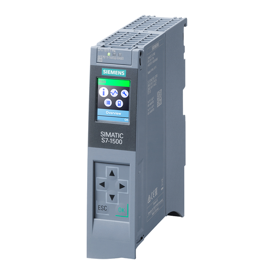
CPU 1511-1 PN
(6ES7511-1AK00-
SIMATIC
S7-1500
CPU 1511-1 PN
(6ES7511-1AK00-0AB0)
Manual
01/2013
A5E31264526-AA
0AB0)
___________________
Preface
___________________
Documentation guide
___________________
Product overview
___________________
Wiring
Interrupts, diagnostics, error,
___________________
and system messages
___________________
Technical specifications
___________________
Dimensional drawing
1
2
3
4
5
A
Advertisement
Table of Contents


Need help?
Do you have a question about the SIMATIC S7-1500 and is the answer not in the manual?
Questions and answers