Table of Contents
Advertisement
Advertisement
Table of Contents

Related Manuals for Crestron TPMC-9


Summary of Contents for Crestron TPMC-9
- Page 1 Crestron TPMC-9 9” Tilt Touch Screen Operations Guide...
- Page 2 Crestron disclaims any proprietary interest in the marks and names of others. Crestron is not responsible for errors in typography or photography.
-
Page 3: Table Of Contents
Crestron TPMC-9 9” Tilt Touch Screen Contents 9” Tilt Touch Screen: TPMC-9 Introduction ..........................1 Features and Functions ....................1 Applications......................... 4 Specifications ......................5 Physical Description ....................7 Setup ............................10 Network Wiring ......................10 Identity Code ......................10 Configuring the Touch Screen ................... -
Page 5: 9" Tilt Touch Screen: Tpmc-9
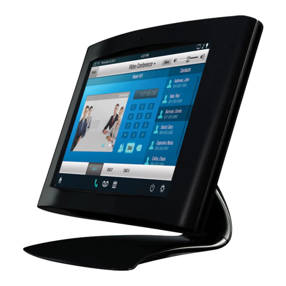
The TPMC-9 Tilt Touch Screen from Crestron delivers high end style and performance in a striking tabletop design. Sleek and compact, the TPMC-9 features a generous 9” (~229 mm) widescreen display with advanced touch screen graphics, IP intercom, audio feedback and high performance H.264 video. - Page 6 IP over Ethernet, eliminating the need for any special audio wiring, switchers or programming. Audio Feedback Customized audio files can be loaded on the TPMC-9 to add another dimension to the touch screen graphics using personalized sounds, button feedback and voice prompts.
- Page 7 Versatile Install Options With its integral tilting base, the TPMC-9 provides a very clean and stylish touch screen solution for small countertops, desks, podiums and bedside tables. The screen tilt is installer adjustable at up to a 45 degree angle for optimal viewing and operation.
-
Page 8: Applications
9” Tilt Touch Screen Crestron TPMC-9 Applications The following diagram shows a TPMC-9 in a typical application. TPMC-9 in a Typical Application 4 • 9” Tilt Touch Screen: TPMC-9 Operations Guide – DOC. 6965E... -
Page 9: Specifications
Crestron TPMC-9 9” Tilt Touch Screen Specifications Specifications for the TPMC-9 are listed in the following table. TPMC-9 Specifications SPECIFICATION DETAILS Touch Screen Display Display Type TFT active matrix color LCD Size 9 inch (229 mm) diagonal Aspect Ratio 15:9 WVGA... - Page 10 3. Refer to “Identity Code” which starts on page 10 for details. 4. The tilt angle must be set to a fixed position for normal use. Adjustment of the tilt angle requires a 5/32” hex wrench (included). 6 • 9” Tilt Touch Screen: TPMC-9 Operations Guide – DOC. 6965E...
-
Page 11: Physical Description
Crestron TPMC-9 9” Tilt Touch Screen Physical Description This section provides information on the connections, controls and indicators available on the TPMC-9. TPMC-9 Physical View Operations Guide – DOC. 6965E 9” Tilt Touch Screen: TPMC-9 • 7... - Page 12 (198 mm) 6.91 in 4.70 in (176 mm) (120 mm) 6.98 in (178 mm) TPMC-9 Overall Dimensions (Side View) 45° 7.09 in (180 mm) 7.02 in (179 mm) 8 • 9” Tilt Touch Screen: TPMC-9 Operations Guide – DOC. 6965E...
- Page 13 Integral 10 foot (3 meter) cable with 10-pin RJ-50 male connector; Connects to included TPS-6X-IMCW interface module; Refer to TPS-6X-IMCW interface module specifications for other connectors and additional information Operations Guide – DOC. 6965E 9” Tilt Touch Screen: TPMC-9 • 9...
-
Page 14: Setup
NOTE: The latest software can be downloaded from the Crestron Web site (www.crestron.com/software). The Net ID of the TPMC-9 has been factory set to 03. The Net IDs of multiple Net ID TPMC-9 devices in the same system must be unique. The Net ID is set using the internal setup menu (refer to “Cresnet”... -
Page 15: Configuring The Touch Screen
NOTE: The only connection required to configure the touch screen is power. Refer to “Hardware Hookup” which starts on page 22 for details. NOTE: The TPMC-9 can take up to 45 seconds to boot to a display after initial power up. - Page 16 Static Default gateway, first touch the DHCP Enabled button. The button text changes to Disabled. Then touch the appropriate button for the address to be entered (or changed). A numeric keypad opens, as shown in the illustration that follows. 12 • 9” Tilt Touch Screen: TPMC-9 Operations Guide – DOC. 6965E...
- Page 17 On the “IP Address” screen, touch Save to keep the change or Cancel to cancel the change and return to the “Ethernet Setup Menu”. Touch << Edit IP Address to return to the previous “IP Address” screen. Operations Guide – DOC. 6965E 9” Tilt Touch Screen: TPMC-9 • 13...
- Page 18 To add an IP entry to a blank slot, first touch one of the Empty IP Table Slot buttons, then touch Add IP. The “Edit IP Table Entry” screen is displayed, as shown below. “Edit IP Table Entry” Screen 14 • 9” Tilt Touch Screen: TPMC-9 Operations Guide – DOC. 6965E...
- Page 19 Then touch Edit IP or Remove IP as appropriate. Editing an entry displays the “Edit IP Table Entry” screen (refer to the second illustration on page 14). Removing an entry displays a message saying Please Operations Guide – DOC. 6965E 9” Tilt Touch Screen: TPMC-9 • 15...
- Page 20 “Video Setup” Screen The “Video Setup” screen contains buttons for adjustment of Brightness, Contrast, Hue, Saturation, Translucency, type of Deinterlacing and amount of Overscan. 16 • 9” Tilt Touch Screen: TPMC-9 Operations Guide – DOC. 6965E...
- Page 21 Setup” screen, touch Return to go back to the main “Setup” menu. Audio From the main “Setup” menu, touch Audio to enter the “Audio Setup” screen, shown in the illustration below. “Audio Setup” Screen Operations Guide – DOC. 6965E 9” Tilt Touch Screen: TPMC-9 • 17...
- Page 22 The “Cresnet Interface” screen contains buttons for setting the Cresnet ID and for enabling or disabling Cresnet. A Control Connection indicator lights in green to show a control system connection. Touch Return to go back to the main “Setup” menu. 18 • 9” Tilt Touch Screen: TPMC-9 Operations Guide – DOC. 6965E...
- Page 23 Test pattern options include Display Color Bars, Display Vertical Lines, Display Gray Scale, Display Test Pattern, Display Grid Pattern, Display RGB Gradient and Display White. From any of these, touch the screen to return to the “Test Operations Guide – DOC. 6965E 9” Tilt Touch Screen: TPMC-9 • 19...
- Page 24 Touch Return to go back to the “Diagnostics” menu. From the “Diagnostics” menu, touch Swipe Test to display the “Swipe Test” screen, as shown in the illustration below. “Swipe Test” Screen 20 • 9” Tilt Touch Screen: TPMC-9 Operations Guide – DOC. 6965E...
- Page 25 Speak into the microphone on the front of the TPMC-9 and the recording is played back to confirm the microphone is functioning. When playback is finished, the display goes back to the “Diagnostics”...
-
Page 26: Hardware Hookup
9” Tilt Touch Screen Crestron TPMC-9 Hardware Hookup The TPMC-9 should be used in a well-ventilated area. Ventilation To prevent overheating, do not operate this product in an area that exceeds the environmental temperature range listed in the table of specifications. -
Page 27: Tilt Adjustment
NET port is not being used to power the module. Tilt Adjustment The head of the TPMC-9 pedestal can be tilted 45 degrees from vertical. The tilt angle must be set to a fixed position for normal use. The tilt mechanism can be adjusted by loosening the tilt clutch using the 5/32”... -
Page 28: Recommended Cleaning
Doing so can crack the screen and damage the touch screen. Enclosure The soft felt bag the TPMC-9 came shipped in can be used to clean the bezel and the rest of the touch screen enclosure. 24 • 9” Tilt Touch Screen: TPMC-9... -
Page 29: Uploading And Upgrading
Finally, program checks can be performed (such as changing the device ID or creating an IP table) to ensure proper functioning. NOTE: Crestron software and any files on the Web site are for authorized Crestron dealers and Crestron Service Providers (CSPs) only. New users must register to obtain access to certain areas of the site (including the FTP site). - Page 30 Click on the TPMC-9 to display information about the device. USB Communication TPMC-9 PC Running Crestron Toolbox The USB port on the TPMC-9 connects to the USB port on the PC: Click Tools | System Info. Click the icon. For Connection Type, select USB. When multiple USB devices are connected, identify the TPMC-9 by entering “TPMC-9”...
-
Page 31: Programs, Projects And Firmware
A defined IP table can be saved to a file or sent to the device. Edit the control system’s IP table to include an entry for the TPMC-9. The entry should list the TPMC-9’s IP ID (specified on the TPMC-9’s IP table) and the internal gateway IP address 127.0.0.1. -
Page 32: Problem Solving
9” Tilt Touch Screen Crestron TPMC-9 Problem Solving Troubleshooting The following table provides corrective action for possible trouble situations. If further assistance is required, please contact a Crestron customer service representative. TPMC-9 Troubleshooting TROUBLE POSSIBLE CAUSE(S) CORRECTIVE ACTION Device does not... -
Page 33: Check Network Wiring
Cresnet power usage of the entire chain. If the unit is home-run from a Crestron system power supply network port, the Cresnet power usage of that unit is the Cresnet power usage of the entire run. The wire gauge and the Cresnet power usage of the run should be used in the following equation to calculate the cable length value on the equation’s left side. -
Page 34: Reference Documents
Crestron worldwide offices on the Crestron Web site (www.crestron.com/offices) for assistance within a particular geographic region. To post a question about Crestron products, log onto the Online Help section of the Crestron Web site (www.crestron.com/onlinehelp). First-time users must establish a user account to fully benefit from all available features. -
Page 35: Return And Warranty Policies
(property or economic damages inclusive) arising from the sale or use of this equipment. Crestron is not liable for any claim made by a third party or made by the purchaser for a third party. - Page 36 Crestron Electronics, Inc. Operations Guide – DOC. 6965E (2027214) 15 Volvo Drive Rockleigh, NJ 07647 Tel: 888.CRESTRON 05.13 Fax: 201.767.7576 Specifications subject to www.crestron.com change without notice.
Need help?
Do you have a question about the TPMC-9 and is the answer not in the manual?
Questions and answers