
Related Manuals for Crestron TPMC-4SMD-FD


Summary of Contents for Crestron TPMC-4SMD-FD
- Page 1 TPMC-4SMD-FD Crestron ® 4.3” Designer Touch Screen with Full Duplex Audio Installation & Operations Guide...
- Page 2 Microsoft Corporation in the United States and/or other countries. Other trademarks, registered trademarks, and trade names may be used in this document to refer to either the entities claiming the marks and names or their products. Crestron disclaims any proprietary interest in the marks and names of others.
-
Page 3: Table Of Contents
Crestron TPMC-4SMD-FD 4.3” Designer Touch Screen Contents 4.3” Designer Touch Screen with Full Duplex Audio: TPMC-4SMD-FD Introduction ..........................1 Features and Functions ....................1 Applications......................... 5 Specifications ......................6 Physical Description ....................8 Setup ............................11 Network Wiring ......................11 Identity Code ...................... -
Page 5: Designer Touch Screen With Full Duplex Audio: Tpmc-4Smd-Fd
The TPMC-4SMD-FD provides a customizable touch screen controller featuring ® Smart Graphics™ technology, H.264 streaming video, audio feedback, and Rava SIP intercom, cohesively merged into one seamless user interface. - Page 6 Available with black or white smooth finish Advanced Touch Screen Control A Crestron touch screen offers an ideal user interface for controlling all the technology in a home, boardroom, classroom, courtroom, or command center. Touch screens do away with piles of remote controls, cluttered wall switches, and cryptic computer screens, simplifying and enhancing the technology.
-
Page 7: Streaming Video
High performance streaming video capability makes it possible to view security cameras and other video sources over the network right on the touch screen. Native support for H.264 and MJPEG formats allows the TPMC-4SMD-FD to display live video images from IP cameras and servers such as the Crestron CEN-NVS200 Network Video Streamer (sold separately). - Page 8 Simple, Versatile Mounting The TPMC-4SMD-FD installs easily using a 1 or 2-gang electrical box or 2-gang UK electrical box. It can also be attached directly to drywall and other surfaces over the front of a roughly 2 inch (~51 mm) square hole. It requires only 1/2 inch (~13 mm) mounting depth while protruding less than an inch (~25 mm) from the wall surface.
-
Page 9: Applications
Crestron TPMC-4SMD-FD 4.3” Designer Touch Screen Applications The following diagram shows a TPMC-4SMD-FD in a typical application. TPMC-4SMD-FD in a Typical Application 4.3” Designer Touch Screen: TPMC-4SMD-FD • 5 Installation & Operations Guide – DOC. 7174F... -
Page 10: Specifications
4.3” Designer Touch Screen Crestron TPMC-4SMD-FD Specifications Specifications for the TPMC-4SMD-FD are listed in the following table. TPMC-4SMD-FD Specifications SPECIFICATION DETAILS Touch Screen Display Display Type TFT active matrix color LCD Size 4.3 inch (109 mm) diagonal Aspect Ratio 16:9 WVGA... - Page 11 3. Requires a minimum cut out or electrical box opening of 1/7” (~43 mm) high x 2.0” (~51 mm) wide. Refer to “Specifications,” which starts on page 5, for electrical box compatibility. 4.3” Designer Touch Screen: TPMC-4SMD-FD • 7 Installation & Operations Guide – DOC. 7174F...
-
Page 12: Physical Description
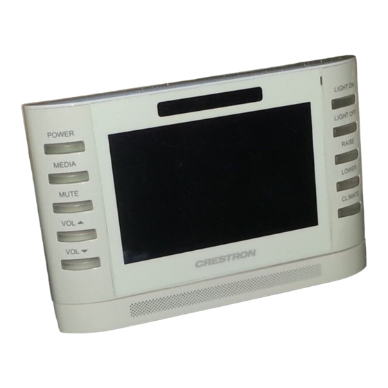
4.3” Designer Touch Screen Crestron TPMC-4SMD-FD Physical Description This section provides information on the connections, controls, and indicators available on the TPMC-4SMD-FD. TPMC-4SMD-FD Physical View 8 • 4.3” Designer Touch Screen: TPMC-4SMD-FD Installation & Operations Guide – DOC. 7174F... - Page 13 Crestron TPMC-4SMD-FD 4.3” Designer Touch Screen TPMC-4SMD-FD Overall Dimensions (Front, Bottom and Rear Views) 4.00 in (102 mm) 6.20 in (158 mm) 0.83 in (21 mm) 1.28 in (33 mm) 0.45 in (12 mm) 1.70 in (44 mm) 3.44 in (88 mm) 2.00 in...
- Page 14 Crestron GLS Series occupancy sensors The pin out table indicates signal connections. dc power applied by Ethernet power sourcing equipment (PSE) can connect to either signal pins or N/C pins. 10 • 4.3” Designer Touch Screen: TPMC-4SMD-FD Installation & Operations Guide – DOC. 7174F...
-
Page 15: Setup
The IP IDs of multiple TPMC-4SMD-FD devices in the same system must be unique. When setting the IP ID, consider the following: • The IP ID of each unit must match an IP ID specified in the Crestron ® Studio software or SIMPL Windows program. -
Page 16: Configuring The Touch Screen
NOTE: The only connection required to configure the touch screen is power. Refer to “Hardware Hookup” on page 30 for details. NOTE: The TPMC-4SMD-FD can take up to 45 seconds to boot to a display after initial power up. The setup screens allow basic configuration procedures prior to regular operation of the touch screen. - Page 17 Add IP, Edit IP and Remove IP, buttons to facilitate editing entries. The Auto Discover button toggles between Enabled and Disabled. “Control System Interface” Menu 4.3” Designer Touch Screen: TPMC-4SMD-FD • 13 Installation & Operations Guide – DOC. 7174F...
- Page 18 Port (41794) button opens the numeric keypad. Touching the CIP ID or Device ID buttons opens a hex keypad, shown in the illustration on the next page. 14 • 4.3” Designer Touch Screen: TPMC-4SMD-FD Installation & Operations Guide – DOC. 7174F...
- Page 19 Control System Interface menu (refer to the illustration at the bottom of page 13). From the Control System Interface menu, touch Back to return to the Ethernet Setup menu. 4.3” Designer Touch Screen: TPMC-4SMD-FD • 15 Installation & Operations Guide – DOC. 7174F...
-
Page 20: Display Settings
4.3” Designer Touch Screen Crestron TPMC-4SMD-FD On the TPMC-4SMD-FD, DHCP is enabled by default. To switch to a static IP address, touch IP Address Settings on the Ethernet Setup menu to access the Edit IP Address Settings screen. (Touch Back to return to the Panel Setup Options menu.) - Page 21 Proximity Sensor Wakes LCD and Hard Key Wakes LCD functions ON or OFF. Touch Back to return to the Display Settings menu. “LCD Wake Options” Screen 4.3” Designer Touch Screen: TPMC-4SMD-FD • 17 Installation & Operations Guide – DOC. 7174F...
- Page 22 Connection, MAC and IP addresses, and provides Keypad Test, Touch Test, Sensor Test, Calibrate Touch, Mic Test, and Test Patterns buttons. Touch Back to return to the Panel Setup Options menu. 18 • 4.3” Designer Touch Screen: TPMC-4SMD-FD Installation & Operations Guide – DOC. 7174F...
- Page 23 From the main Diagnostics menu, touch Touch Test to display the following screen, which includes a Calibrate button to initiate touch screen calibration. The Calibrate Touch button on the Diagnostics menu also initiates touch screen calibration. 4.3” Designer Touch Screen: TPMC-4SMD-FD • 19 Installation & Operations Guide – DOC. 7174F...
- Page 24 Inactive to Active as appropriate for each sensor’s activity. Similarly, the TPMC-4SMD-FD’s own proximity sensor’s indicator changes from Inactive to Active when the TPMC-4SMD-FD senses motion in front of the unit. Use the Sensor Strength controls to adjust proximity sensor sensitivity.
- Page 25 The button label changes to RECORDING/PLAYBACK and the screen displays a "Mic test in progress" message, as shown in the illustration on the following page. 4.3” Designer Touch Screen: TPMC-4SMD-FD • 21 Installation & Operations Guide – DOC. 7174F...
-
Page 26: Test Patterns
Crestron TPMC-4SMD-FD Mic Test In Progress Screen Speak into the microphone on the front of the TPMC-4SMD-FD, and the recording is played back to confirm the microphone is functioning. After playback, the button reverts to its original Mic Test label. -
Page 27: Changing The Button Inserts
4.3” Designer Touch Screen Changing the Button Inserts The TPMC-4SMD-FD ships with 10 “hard key” push buttons for quick access to commonly used functions. For a clean appearance, either column of buttons may be removed and covered using the no-button covers provided. -
Page 28: Installation
The TPMC-4SMD-FD touch screen installs simply and cleanly into a standard electrical box. The TPMC-4SMD-FD is supplied with screws for installation into an electrical box. Mounting in a US Electrical Box To mount the TPMC-4SMD-FD into an electrical box, use the following procedure: 1. - Page 29 Crestron TPMC-4SMD-FD 4.3” Designer Touch Screen Mounting the TPMC-4SMD-FD into an Electrical Box Electrical Box Screws (2) #06-32 x 1 1/2” (2007254) 4.3” Designer Touch Screen: TPMC-4SMD-FD • 25 Installation & Operations Guide – DOC. 7174F...
- Page 30 4.3” Designer Touch Screen Crestron TPMC-4SMD-FD Mounting the TPMC-4SMD-FD into a 2-Gang Electrical Box 2-Gang Electrical Box Screws (4) #06-32 x 1 1/2” (2007254) 26 • 4.3” Designer Touch Screen: TPMC-4SMD-FD Installation & Operations Guide – DOC. 7174F...
- Page 31 Electrical Box Screws (2) #06-32 x 1 1/2” (2007254) 3. Carefully position the front of the TPMC-4SMD-FD over the back panel and gently snap it into place, as shown in the following illustration. 4.3” Designer Touch Screen: TPMC-4SMD-FD • 27...
- Page 32 For secure applications: security type Torx (2029108 or 2029112) 4. Use two of the included #04-40 x 3/4” screws to secure the TPMC-4SMD-FD, as shown in the illustration above: For standard applications, use the Phillips screws (2029111 or 2029110). ®...
- Page 33 Crestron TPMC-4SMD-FD 4.3” Designer Touch Screen Mounting in a European Electrical Box To mount the TPMC-4SMD-FD into a European electrical box, use the following procedure: 1. Insert a small slot-head screwdriver into the hole shown in the illustration at the bottom of page 24 and gently separate the back of the TPMC-4SMD-FD.
-
Page 34: Hardware Hookup
Make the necessary connections as called out in the illustration that follows this paragraph. When making connections to the TPMC-4SMD-FD, use Crestron power supplies for Crestron equipment. Apply power after all connections have been made. Hardware Connections for the TPMC-4SMD-FD... -
Page 35: Uploading And Upgrading
(including the FTP site). Establishing Communication Use Crestron Toolbox software for communicating with the TPMC-4SMD-FD; refer to the Crestron Toolbox software help file for details. There is a single method of communication: TCP/IP communication. Ethernet Communication... -
Page 36: Programs, Projects And Firmware
Crestron Toolbox software. For details on uploading and upgrading, refer to the Crestron Studio software help file, the SIMPL Windows help file, the VT ®... -
Page 37: Problem Solving
Crestron TPMC-4SMD-FD 4.3” Designer Touch Screen Problem Solving Troubleshooting The following table provides corrective action for possible trouble situations. If further assistance is required, please contact a Crestron customer service representative. TPMC-4SMD-FD Troubleshooting TROUBLE POSSIBLE CAUSE(S) CORRECTIVE ACTION Device does not... -
Page 38: Further Inquiries
To locate specific information or to resolve questions after reviewing this guide, contact Crestron's True Blue Support at 1-888-CRESTRON [1-888-273-7876]. For assistance within a particular geographical region, refer to the listing of Crestron worldwide offices at www.crestron.com/offices. To post a question about Crestron products, log onto www.crestron.com/onlinehelp. - Page 39 Crestron TPMC-4SMD-FD 4.3” Designer Touch Screen This page is intentionally left blank. 4.3” Designer Touch Screen: TPMC-4SMD-FD • 35 Installation & Operations Guide – DOC. 7174F...
- Page 40 Crestron Electronics, Inc. Installation & Operations Guide – DOC. 7174F 15 Volvo Drive Rockleigh, NJ 07647 (2030553) Tel: 888.CRESTRON 09.16 Fax: 201.767.7576 Specifications subject to www.crestron.com change without notice.
Need help?
Do you have a question about the TPMC-4SMD-FD and is the answer not in the manual?
Questions and answers