Crestron TPMC-4SM Installation & Operation Manual
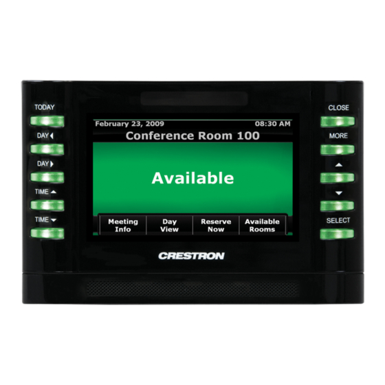
4.3 inch room scheduling touch
Hide thumbs
Also See for TPMC-4SM:
- Operations & installation manual (44 pages) ,
- Design manual (84 pages) ,
- Quick manual (60 pages)

Related Manuals for Crestron TPMC-4SM


Summary of Contents for Crestron TPMC-4SM
- Page 1 TPMC-4SM Crestron ® 4.3” Room Scheduling Touch Screen Installation & Operations Guide...
- Page 2 Crestron disclaims any proprietary interest in the marks and names of others. Crestron is not responsible for errors in typography or photography.
- Page 3 Crestron TPMC-4SM 4.3” Room Scheduling Touch Screen Contents 4.3” Room Scheduling Touch Screen: TPMC-4SM Introduction ..........................1 Features and Functions ....................1 Applications......................... 5 Specifications ......................6 Physical Description ....................8 Setup ............................11 Network Wiring ......................11 Identity Code ......................11 Configuring the Touch Screen ...................
-
Page 5: Introduction
An incredibly thin profile and small footprint allow the TPMC-4SM to be installed in places other touch screens cannot go, providing the choice of mounting to a standard electrical box or to virtually any flat surface;... -
Page 6: Features And Functions
Available with black or white smooth finish Advanced Touch Screen Control A Crestron touch screen offers an ideal user interface for controlling all the technology in a home, boardroom, classroom, courtroom, or command center. Touch screens do away with piles of remote controls, cluttered wall switches, and cryptic computer screens, simplifying and enhancing the technology. -
Page 7: Streaming Video
High performance streaming video capability makes it possible to view security cameras and other video sources over the network right on the touch screen. Native support for H.264 and MJPEG formats allows the TPMC-4SM to display live video images from IP cameras and servers such as the Crestron CEN-NVS200 Network Video Streamer (sold separately). - Page 8 Single Wire Connectivity A simple Ethernet LAN connection is all that is required to wire the TPMC-4SM, containing all control, video, intercom, and power signals within a single wire. Power over Ethernet Using PoE technology, the TPMC-4SM gets its operating power through the LAN wiring.
-
Page 9: Applications
Crestron TPMC-4SM 4.3” Room Scheduling Touch Screen Applications The following diagram shows a TPMC-4SM in a typical application. TPMC-4SM in a Typical Application 4.3” Room Scheduling Touch Screen: TPMC-4SM • 5 Installation & Operations Guide – DOC. 6845F... -
Page 10: Specifications
4.3” Room Scheduling Touch Screen Crestron TPMC-4SM Specifications Specifications for the TPMC-4SM are listed in the following table. TPMC-4SM Specifications SPECIFICATION DETAILS Touch Screen Display Display Type TFT active matrix color LCD Size 4.3 inch (109 mm) diagonal Aspect Ratio... - Page 11 Virtual Mouse & Keyboard ® Software for Windows Software 1. Wakes the touch screen and backlight. 2. Refer to “Identity Code” on page 11 for details. 4.3” Room Scheduling Touch Screen: TPMC-4SM • 7 Installation & Operations Guide – DOC. 6845F...
-
Page 12: Physical Description
4.3” Room Scheduling Touch Screen Crestron TPMC-4SM Physical Description This section provides information on the connections, controls, and indicators available on the TPMC-4SM. TPMC-4SM Physical View 8 • 4.3” Room Scheduling Touch Screen: TPMC-4SM Installation & Operations Guide – DOC. 6845F... - Page 13 Crestron TPMC-4SM 4.3” Room Scheduling Touch Screen TPMC-4SM Overall Dimensions (Front, Bottom and Rear Views) 3.47 in (89 mm) 6.20 in (158 mm) 0.75 in (19 mm) 1.21 in (31 mm) 0.46 in (12 mm) 1.70 in (44 mm) 2.36 in (60 mm) 2.00 in...
- Page 14 The pin out table indicates signal connections. dc power applied by Ethernet power sourcing equipment (PSE) can connect to either signal pins or N/C pins. 10 • 4.3” Room Scheduling Touch Screen: TPMC-4SM Installation & Operations Guide – DOC. 6845F...
-
Page 15: Setup
The IP ID is set within the TPMC-4SM’s IP table using Crestron Toolbox™ software. For information on setting an IP table, refer to the Crestron Toolbox software help file. The IP IDs of multiple TPMC-4SM devices in the same system must be unique. -
Page 16: Configuring The Touch Screen
NOTE: The only connection required to configure the touch screen is power. Refer to “Hardware Hookup” on page 26 for details. NOTE: The TPMC-4SM can take up to 45 seconds to boot to a display after initial power up. The setup screens allow basic configuration procedures prior to regular operation of the touch screen. - Page 17 Each field opens an on-screen keyboard appropriate for the field. For example, touching the IP Address / Hostname field opens the on-screen keyboard illustrated on the following page. 4.3” Room Scheduling Touch Screen: TPMC-4SM • 13 Installation & Operations Guide – DOC. 6845F...
- Page 18 Settings screen, touch Save to keep the new setting or Cancel to cancel it. On the TPMC-4SM, DHCP is enabled by default. To switch to a static IP address, touch IP Address Settings on the Ethernet Setup menu to access the Edit IP Address Settings screen.
- Page 19 Volume, Wave Volume, Mute controls for all three volumes, and a Play Test Wave button. Touch Back to return to the Panel Setup Options menu. “Audio Settings” Screen 4.3” Room Scheduling Touch Screen: TPMC-4SM • 15 Installation & Operations Guide – DOC. 6845F...
-
Page 20: Display Settings
Touch Left LED Color Settings to enter the Display Settings screen for Left Bank LED Color. Options are Green, Red, and Off. Touch Back to return to the main Display Settings menu. 16 • 4.3” Room Scheduling Touch Screen: TPMC-4SM Installation & Operations Guide – DOC. 6845F... - Page 21 On the Panel Setup Options menu, the About button opens a small window displaying the Firmware Version and the OS Image Version. Click OK to close the window. 4.3” Room Scheduling Touch Screen: TPMC-4SM • 17 Installation & Operations Guide – DOC. 6845F...
- Page 22 On the main Diagnostics menu, touch Touch Test to display the following screen, which includes a Calibrate button to initiate touch screen calibration. The Calibrate Touch button on the Diagnostics menu also initiates touch screen calibration. 18 • 4.3” Room Scheduling Touch Screen: TPMC-4SM Installation & Operations Guide – DOC. 6845F...
- Page 23 Inactive to Active as appropriate for each sensor’s activity. Similarly, the TPMC-4SM’s own proximity sensor’s indicator changes from Inactive to Active when the TPMC-4SM senses motion in front of the unit. Touch Back to return to the main Diagnostics menu.
-
Page 24: Test Patterns
TPMC-4SM’s built-in microphone. The button label changes to RECORDING/PLAYBACK. Speak into the microphone on the front of the TPMC-4SM (for five seconds), and the recording is played back to confirm the microphone is functioning. After playback, the button reverts to its original Mic Test label. -
Page 25: Changing The Button Inserts
4.3” Room Scheduling Touch Screen Changing the Button Inserts The TPMC-4SM ships with 10 “hard key” push buttons for quick access to commonly used functions. For a clean appearance, either column of buttons may be removed and covered using the no-button covers provided. -
Page 26: Installation
The TPMC-4SM is supplied with screws for installation into an electrical box. Mounting in a US Electrical Box NOTE: When mounting the TPMC-4SM into an electrical box, the box must be installed horizontally. To mount the TPMC-4SM into an electrical box, use the following procedure: 1. - Page 27 NOTE: Use the left and right screw holes for attachment to the electrical box. Mounting the TPMC-4SM into an Electrical Box 3. Carefully position the front of the TPMC-4SM over the back panel and gently snap it into place, as shown in the following illustration.
- Page 28 4.3” Room Scheduling Touch Screen Crestron TPMC-4SM 4. Use two of the included #04-40 x 1/4” screws to secure the TPMC-4SM, as shown in the following illustration: For standard applications, use the Phillips screws (2007152 or 2007160). ® b. For secure applications, use the security type Torx screws (2025311 or 2025312) along with the included Torx screwdriver bit (2025915).
- Page 29 1. Insert a small slot-head screwdriver into the hole shown in the illustration at the top of page 21 and gently separate the back of the TPMC-4SM. 2. Use the two included #4B x 3/4” screws (2019088) to attach the back panel to the electrical box, as shown in the following illustration.
-
Page 30: Hardware Hookup
Make the necessary connections as called out in the illustration that follows this paragraph. When making connections to the TPMC-4SM, use Crestron power supplies for Crestron equipment. Apply power after all connections have been made. Hardware Connections for the TPMC-4SM... -
Page 31: Uploading And Upgrading
Finally, program checks can be performed (such as changing the device ID or creating an IP table) to ensure proper functioning. NOTE: Crestron software and any files on the website are for authorized Crestron dealers and Crestron Service Providers (CSPs) only. New users must register to obtain access to certain areas of the site (including the FTP site). -
Page 32: Programs, Projects And Firmware
3. A defined IP table can be saved to a file or sent to the device. Edit the control system’s IP table to include an entry for the TPMC-4SM. The entry should list the TPMC-4SM’s IP ID (specified on the TPMC-4SM’s IP table), and the internal gateway IP address 127.0.0.1. -
Page 33: Problem Solving
Crestron TPMC-4SM 4.3” Room Scheduling Touch Screen Problem Solving Troubleshooting The following table provides corrective action for possible trouble situations. If further assistance is required, please contact a Crestron customer service representative. TPMC-4SM Troubleshooting TROUBLE POSSIBLE CAUSE(S) CORRECTIVE ACTION Device does not... -
Page 34: Further Inquiries
To locate specific information or to resolve questions after reviewing this guide, contact Crestron's True Blue Support at 1-888-CRESTRON [1-888-273-7876]. For assistance within a particular geographical region, refer to the listing of Crestron worldwide offices at www.crestron.com/offices. To post a question about Crestron products, log onto www.crestron.com/onlinehelp. - Page 35 Crestron TPMC-4SM 4.3” Room Scheduling Touch Screen This page is intentionally left blank. 4.3” Room Scheduling Touch Screen: TPMC-4SM • 31 Installation & Operations Guide – DOC. 6845F...
- Page 36 Crestron Electronics, Inc. Installation & Operations Guide – DOC. 6845F 15 Volvo Drive Rockleigh, NJ 07647 (2024510) Tel: 888.CRESTRON 09.16 Fax: 201.767.7576 Specifications subject to www.crestron.com change without notice.
Need help?
Do you have a question about the TPMC-4SM and is the answer not in the manual?
Questions and answers