Table of Contents
Advertisement
Quick Links
MP135E
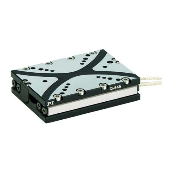
Q-545 Precision Linear Stage
User Manual
Version: 1.1.0
PI miCos GmbH, Freiburger Strasse 30, 79427 Eschbach, Germany
Phone +49 7634 5057-0, Fax +49 7634 5057-99, Email info@pimicos.com, www.pi.ws
Date: 13.05.2019
This document describes the following products:
Q-545.140
Q-Motion® linear stage, piezoelectric inertia
drive, 13 mm travel range, linear encoder,
1 nm resolution, 8 N drive force,
dimensions 45 × 48 × 15 mm (W × L × H),
vacuum compatible to 10
Q-545.240
Q-Motion® linear stage, piezoelectric inertia
drive, 26 mm travel range, linear encoder,
1 nm resolution, 8 N drive force,
dimensions 45 × 63 × 15 mm (W × L × H),
vacuum compatible to 10
-6
hPa
-6
hPa
Advertisement
Table of Contents

Related Manuals for PI Q-Motion Q-545 Series


Summary of Contents for PI Q-Motion Q-545 Series
- Page 1 1 nm resolution, 8 N drive force, dimensions 45 × 63 × 15 mm (W × L × H), vacuum compatible to 10 PI miCos GmbH, Freiburger Strasse 30, 79427 Eschbach, Germany Phone +49 7634 5057-0, Fax +49 7634 5057-99, Email info@pimicos.com, www.pi.ws...
- Page 2 The patents held by PI are found in our patent list: http://www.physikinstrumente.com/en/about-pi/patents © 2019 Physik Instrumente (PI) GmbH & Co. KG, Karlsruhe, Germany. The text, photographs and drawings in this manual are protected by copyright. With regard thereto, Physik Instrumente (PI) GmbH & Co. KG retains all the rights.
-
Page 3: Table Of Contents
Contents About this Document Objective and Target Audience of this User Manual..........1 Symbols and Typographic Conventions..............1 Definition of Terms ..................... 2 Figures ........................2 Other Applicable Documents ..................3 Downloading Manuals ....................3 Safety Intended Use ......................5 General Safety Instructions .................. - Page 4 Connecting the Q-545 to the Electronics ..............34 5.6.1 Overview: Connecting for Atmospheric Operation ........34 5.6.2 Overview: Connecting for Operating in a Vacuum ........35 5.6.3 Connecting the Q-545 to the Electronics ............ 36 Startup and Operation General Notes on Startup and Operation ..............37 Starting and Operating the Q-545 ................
-
Page 5: About This Document
1 About this Document About this Document In this Chapter Objective and Target Audience of this User Manual ..............1 Symbols and Typographic Conventions ..................1 Definition of Terms ........................2 Figures ............................2 Other Applicable Documents ......................3 Downloading Manuals ........................3 Objective and Target Audience of this User Manual This manual contains information necessary for the intended use of the Q-545. -
Page 6: Definition Of Terms
1 About this Document Symbol/ Meaning Label Action consisting of several steps whose sequential order must be observed Action consisting of one or several steps whose sequential order is irrelevant List item p. 5 Cross-reference to page 5 RS-232 Labeling of an operating element on the product (example: socket of the RS-232 interface) -
Page 7: Other Applicable Documents
1 About this Document Other Applicable Documents The devices and software tools from PI mentioned in this documentation are described in their own manuals. Description Document E-873.1AT Q-Motion® controller, 1 channel, TCP/IP, USB PZ274E User manual and RS-232 Interface, benchtop device (industry) E-873.3QTU Q-Motion®... - Page 8 Click the links in the browser window to change to the content for your product and log in using the access data that you received. General procedure: 1. Open the website www.pi.ws. 2. If access to the manuals is protected by a password: a) Click Login.
-
Page 9: Safety
2 Safety Safety In this Chapter Intended Use ..........................5 General Safety Instructions......................5 Organizational Measures ....................... 6 Measures for Handling Vacuum-Compatible Products ..............6 Intended Use The Q-545 is a laboratory device as defined by DIN EN 61010-1. It is intended for indoor use and use in an environment that is free of dirt, oil, and lubricants. -
Page 10: Organizational Measures
Measures for Handling Vacuum-Compatible Products Attention must be paid to appropriate cleanliness when the positioner is to be used in a vacuum. All parts are cleaned at PI before assembly. Powder-free gloves are worn during assembly and measuring. Touch the positioner only with powder-free gloves. -
Page 11: Product Description
3 Product Description Product Description In this Chapter Model Overview ..........................7 Product View ..........................8 Product Labeling ..........................9 Scope of Delivery ......................... 10 Accessories ........................... 10 Suitable Electronics ........................11 Technical Features ........................11 Model Overview The Q-545 is available in the following versions: Order number Product name Q-545.140 Q-Motion®... -
Page 12: Product View
3 Product Description Product View Figure 1: Example for models with sensor: Q-545.140 positioner Motion platform Cable exit for drive connector Warning sign "Electrostatic sensitive devices" Connector for drive and sensor: D-sub 15 (m) ESD protection cap Type plate p. 9 Cable exit for sensor connector Inner guide element (2×) Outer guide element (2×) -
Page 13: Product Labeling
2 and 3 = year of manufacture, 4 to 9 = consecutive number Product name (example), the characters Q-545.240 following the period refer to the model Old equipment disposal WWW.PI.WS Manufacturer's address (website) Q-545 Precision Linear Stage MP135E Version: 1.1.0... -
Page 14: Scope Of Delivery
3 Product Description Scope of Delivery The Q-545 is delivered with the following components: Item Components Q-545 Positioner according to order (p. 7) Screw set for mounting the Q-545, consisting of: 5861500010 2 dowel pins, A2 2.5 m6 × 5 ISO 8734 ... -
Page 15: Suitable Electronics
Settings for the sensor: Interpolation rate, corrections to hysteresis, phase and offset, gain values When switched on or rebooted, controllers from PI read the data from the ID chip. For more information on ID chip detection, see the manual for the controller. Q-545 Precision Linear Stage MP135E Version: 1.1.0... -
Page 17: Unpacking
INFORMATION Attention must be paid to appropriate cleanliness when the positioner is to be used in a vacuum. All parts are cleaned at PI before assembly. Powder-free gloves are worn during assembly and measuring. Touch the positioner only with powder-free gloves. -
Page 19: Installation
5 Installation Installation In this Chapter General Notes on Installation ...................... 15 Avoiding Mounting Errors ......................17 Mounting the Q-545 onto an Underlying Surface and Connecting it to a Protective Earth Conductor ............................ 21 Building a Multi-Axis System ......................24 Fixing the Load to the Q-545 ....................... - Page 20 NOTICE Damage from unsuitable cables! Unsuitable cables can damage the electronics. Use cables provided by PI only for connecting the Q-545 to the electronics. INFORMATION For optimum repeatability, all components must be firmly affixed to each other. INFORMATION The positive direction of motion of the axis is specified in the product view (p.
-
Page 21: Avoiding Mounting Errors
5 Installation Avoiding Mounting Errors Mounting the Q-545 onto an underlying surface Figure 5: Incorrect mounting on an uneven surface, schematic representation Line, black: Uneven underlying surface Arrows, white: Effect of force by tightening the screws when fixing to the underlying surface Arrows, black: The guide elements are pushed outwards, play occurs between the inner and outer guide elements... - Page 22 5 Installation Building a Multi-Axis System Figure 6: Incorrect mounting of an XY system; schematic representation Bars, black: Excessively long or thick locating pins for aligning the upper to the lower positioner Arrows, white: Effect of force by tightening the screws when fixing the upper to the lower positioner Lines, black: Warping of the upper and lower positioner's contact surfaces Arrows, black:...
- Page 23 5 Installation Fixing the load to the Q-545 Figure 7: Incorrect mounting: Torque on Figure 8: Correct mounting: Hold the the motion platform damages motion platform firmly to the positioner avoid torque on the motion platform NOTICE Impermissible torque and forces! Torque and forces on the motion platform could damage the positioner.
- Page 24 5 Installation NOTICE Damage due to unfavorable load center! A load's center of gravity not at the center of the motion platform subjects the positioner to torque. The torque reduces the accuracy and could damage the positioner. Make sure that the gap between the load's center of gravity and the motion platform's center is as small as possible in all directions.
-
Page 25: Mounting The Q-545 Onto An Underlying Surface And Connecting It To A Protective Earth Conductor
5 Installation NOTICE Damage due to mounting a load with uneven contact surface! Mounting a load with an uneven contact surface could warp the Q-545. Warping reduces the accuracy, the drive force, and the maximum velocity. Fix a load onto the Q-545 only if its contact surface is flat. The recommended flatness for the contact surface is ≤10 µm. - Page 26 5 Installation Figure 11: Example Q-545.140, left: View from below; right: View from top Two locating holes in the bottom of the positioner are used for aligning on an underlying surface. Four M2.5 screws are used to fix the positioner to an underlying surface. Possible orientations of the Q-545 Orientation of the motion Influencing factors...
- Page 27 5 Installation Orientation of the motion Influencing factors axis Any orientation of the motion axis; here: Vertical mounting with vertical orientation of the motion axis g = gravity 1 = positive direction of the motion axis 2 = load capacity, any (p. 2), max. 0.1 kg Requirements ...
-
Page 28: Building A Multi-Axis System
5 Installation Mounting the Q-545 onto an underlying surface and connecting it to a protective earth conductor 1. Aligning the Q-545 on underlying surface using the locating pins: a) Insert the two locating pins into the locating holes in the bottom of the Q-545 (see figure above) or in the underlying surface. -
Page 29: General Information On Building A Multi-Axis System
5 Installation Figure 12: Example for an XYZ system: Three Q-545.140 mounted using an adapter bracket Lower positioner Middle positioner Q-145.1001 adapter bracket (for use in a vacuum to 10 hPa) Upper positioner 5.4.1 General Information on Building a Multi-Axis System ... - Page 30 5 Installation Requirements You have read and understood the general notes on installation (p. 15). You have read and understood the general notes on building a multi-axis system (p. 25). The positioners are disconnected from the electronics. ...
-
Page 31: Building A Z System With An Adapter Bracket
5 Installation 1. Insert the two locating pins into the locating holes in the bottom of the upper Q-545 or in the motion platform of the lower Q-545 (see figure above). It must be possible to insert the locating pins easily. 2. - Page 32 5 Installation Orientation of adapter bracket and upper positioner to the lower positioner: Combination of 0° 90° 180° 270° positioners and adapter brackets: 2 Q-545.140 + Q-145.1001 2 Q-545.240 + Not possible. The Not possible. The motion platforms of motion platforms of the positioners the positioners collide with each...
- Page 33 5 Installation Requirements You have read and understood the general notes on installation (p. 15). You have read and understood the general notes on building a multi-axis system (p. 25). You have accounted for the space required to route cables according to regulations and without bending them.
- Page 34 5 Installation Building a Z system Figure 14: Example: Building an XZ system consisting of two Q-545.140 and a Q-145.1001 adapter bracket Lower positioner 2 dowel pins, 2.5 m6 × 4 for use as locating pins; from the scope of delivery of the adapter bracket Q-145.200 adapter bracket 4 socket head screws M2.5x8 for mounting the adapter bracket on...
- Page 35 5 Installation Figure 15: Adapter bracket with screws and locating pins. The locating pins for alignment on the lower positioner must be inserted into the bracket from below and up to the limit stop. 1. Fix the upper positioner to the long side of the adapter bracket: a) Align the upper positioner so that the cable exit points away from the origin of the sides of the adapter bracket;...
-
Page 36: Fixing The Load To The Q-545
5 Installation Fixing the Load to the Q-545 Requirements You have read and understood the general notes on installation (p. 15). You have mounted the positioner onto an underlying surface (p. 21) properly or on a Q-545 (p. 24). ... - Page 37 5 Installation Fixing the load to the Q-545 Figure 16: Q-545.140 The arrows identify the following mounting holes in the Q-545.140's motion platform: For aligning the load: White arrows: Locating holes Ø 2.5 mm H7, depth 2.5 mm For fixing the load: Dark-gray arrows: M2.5 threaded holes, depth 5 mm Light-gray arrows:...
-
Page 38: Connecting The Q-545 To The Electronics
5 Installation If you use locating pins to align the load: a) Insert the locating pins into the locating holes in the motion platform or in the load. b) Put the load on the motion platform so that the locating pins are inserted into the corresponding locating holes on the other side. -
Page 39: Overview: Connecting For Operating In A Vacuum
5 Installation 5.6.2 Overview: Connecting for Operating in a Vacuum Figure 19: Connecting the Q-545 to suitable electronics for operating in a vacuum Controller Extension cable Vacuum feedthrough for pressure to 10-6 hPa Mechanics Figure 20: Example for installing the C-815.VF vacuum feedthrough. Left: Vacuum side, right: Air side Q-545's connector on the vacuum side Example of a vacuum feedthrough, part of a vacuum chamber Sealing ring... -
Page 40: Connecting The Q-545 To The Electronics
5 Installation Installing the vacuum feedthrough For C-815.VF vacuum feedthrough: Install the vacuum feedthrough so that the D-sub 15 (f) socket is in the vacuum chamber. Pay attention to the maximum torque of 0.9 Nm. 5.6.3 Connecting the Q-545 to the Electronics Requirements ... -
Page 41: Startup And Operation
6 Startup and Operation Startup and Operation In this Chapter General Notes on Startup and Operation ..................37 Starting and Operating the Q-545 ....................40 General Notes on Startup and Operation CAUTION Risk of electric shock if the protective earth conductor is not connected! If a protective earth conductor is not or not properly connected, dangerous touch voltages can occur on the Q-545 in the case of malfunction or failure of the system. - Page 42 Operating voltages that are too high or incorrectly connected can cause damage to the Q-545. Operate the Q-545 only with controllers/drivers and original accessories from PI. Do not exceed the operating voltage range (p. 51) for which the Q-545 is specified.
- Page 43 6 Startup and Operation NOTICE Damage due to collisions! Collisions can damage the positioner, the load to be moved, and the surroundings. Make sure that no collisions are possible between the positioner, the load to be moved, and the surroundings in the motion range of the positioner. ...
-
Page 44: Starting And Operating The Q-545
PIMicosStages3.dat. The records in the positioner database are updated regularly. Install the PI Update Finder from the product CD for the electronics onto your PC and update PIMicosStages3.dat on your PC. Further information can be found in the user manual for the electronics. - Page 45 6 Startup and Operation 2. If necessary: Adapt the parameters for the operating frequency in step mode or the velocity (see the user manual for the electronics) to your application (see also "General Notes on Startup and Operation" (p. 37) and "Operating Time" (p. 52)). PIMikroMove is used in the user manual for the electronics to describe startup and operation.
-
Page 47: Maintenance
7 Maintenance Maintenance In this Chapter General Notes on Maintenance ....................43 Performing a Maintenance Run ....................43 Cleaning the Q-545 ........................43 General Notes on Maintenance NOTICE Damage due to improper maintenance! Improper maintenance can lead to misalignment and failure of the Q-545. ... -
Page 49: Troubleshooting
8 Troubleshooting Troubleshooting Problem Possible causes Solution Function The electronics Load the parameter set from the positioner impairment database that corresponds to the Q-545 model. were replaced after system If necessary: Set the parameters for the The positioner modification electronics in PIMikroMove so that they... - Page 50 8 Troubleshooting Problem Possible causes Solution Unsuitable ambient Operate the Q-545 in a clean environment only conditions and only under permissible ambient conditions (p. 51). Drive wear Replace the Q-545 and make sure that the operating parameters of the electronics are adapted to the positioner.
-
Page 51: Customer Service
9 Customer Service Customer Service For inquiries and orders, contact your PI sales engineer or send us an email (service@pi.de). If you have any questions concerning your system, provide the following information: − Product and serial numbers of all products in the system −... -
Page 53: Technical Data
10 Technical Data Technical Data In this Chapter Specifications ..........................49 Operating Time ..........................52 Dimensions ..........................53 Pin Assignment ..........................59 10.1 Specifications 10.1.1 Data Table Motion Q-545.140 Q-545.240 Unit Tolerance Active axis Travel range Maximum velocity, mm/s closed loop Minimum incremental typ. - Page 54 10 Technical Data Mechanical properties Q-545.140 Q-545.240 Unit Tolerance Mass without cable and ±10 % connector Mass incl. cable and ±10 % connector Guide type Crossed roller Crossed roller bearing with anti- bearing with anti- creep system creep system Axial stiffness N/µm ±10 % Lateral stiffness...
-
Page 55: Maximum Ratings
10 Technical Data 10.1.2 Maximum Ratings The Q-545 positioner is designed for the following operating data: Maximum operating Maximum operating frequency Maximum power consumption voltage 48 V 20 kHz 30 W 10.1.3 Ambient Conditions and Classifications Pay attention to the following ambient conditions and classifications for the Q-545: Area of application For indoor use only Maximum altitude... -
Page 56: Operating Time
10 Technical Data 10.2 Operating Time The operating frequency in step mode or the velocity and the duration of motion affect the lifetime of the positioner. In order to prevent overheating and increased wear, the duration of motion at the specified velocity or operating frequency may not exceed the values specified in the following table. -
Page 57: Dimensions
10 Technical Data 10.4 Dimensions 10.4.1 Q-545.140 Dimensions in mm. Note that a comma is used instead of a decimal point in the drawings Figure 22: Q-545.140 Q-545 Precision Linear Stage MP135E Version: 1.1.0... -
Page 58: Q-545.240
10 Technical Data 10.4.2 Q-545.240 Dimensions in mm. Note that a comma is used instead of a decimal point in the drawings Figure 23: Q-545.240 Version: 1.1.0 MP135E Q-545 Precision Linear Stage... -
Page 59: Q-145.1001 Adapter Bracket
10 Technical Data 10.4.3 Q-145.1001 Adapter Bracket Dimensions in mm. Note that a comma is used in the drawings instead of a decimal point. Figure 24: Q-145.1001 Adapter Bracket Q-545 Precision Linear Stage MP135E Version: 1.1.0... -
Page 60: Q-145.200 Adapter Bracket
10 Technical Data 10.4.4 Q-145.200 Adapter Bracket Dimensions in mm. Note that a comma is used in the drawings instead of a decimal point. Figure 25: Q-145.200 adapter bracket, dimensions of the Q-145.20U adapter bracket are identical Version: 1.1.0 MP135E Q-545 Precision Linear Stage... -
Page 61: C-815.Vf Vacuum Feedthrough For 10 Hpa
10 Technical Data 10.4.5 C-815.VF Vacuum Feedthrough for 10 Dimensions in mm. Note that a comma is used in the drawings instead of a decimal point. Figure 26: C-815.VF vacuum feedthrough D-sub 15 (m/f) Q-545 Precision Linear Stage MP135E Version: 1.1.0... - Page 62 10 Technical Data Recommended vacuum chamber opening for the C-815.VF vacuum feedthrough for Dimensions in mm. Note that a comma is used in the drawings instead of a decimal point. Figure 27: Top: View of the opening on the air side; middle: Section of the vacuum chamber as specified by the customer;...
-
Page 63: Pin Assignment
10 Technical Data 10.5 Pin Assignment 10.5.1 Q-545 (Vacuum Compatible to 10 hPa) Connector: D-sub 15 (m) The D-sub 15 connector (m) transmits the signals from the drive, the sensor, and the ID chip. Figure 28: D-sub 15 (m) connector Signal* Function Direction... -
Page 64: C-815.Vf Vacuum Feedthrough
10 Technical Data 10.5.2 C-815.VF Vacuum Feedthrough D-sub 15 (m/f) Figure 29: Vacuum side: D-sub 15 (f) Figure 30: Air side: D-sub 15 (m) panel plug Vacuum side (f) Air side (m) Signal Function REF - Reference signal differential (-) Motor (-) Motor signal differential (-) Motor (+) -
Page 65: Old Equipment Disposal
PI miCos equipment made available on the market after 13 August 2005 without charge. Any old PI miCos equipment can be sent free of charge to the following address: PI miCos GmbH Freiburger Strasse 30... -
Page 67: Eu Declaration Of Conformity
12 EU Declaration of Conformity EU Declaration of Conformity For the Q-545, an EU Declaration of Conformity has been issued in accordance with the following European directives: Low Voltage Directive EMC Directive RoHS Directive The applied standards certifying the conformity are listed below. Safety (Low Voltage Directive): EN 61010-1 EMC: EN 61326-1 RoHS: EN 50581...
Need help?
Do you have a question about the Q-Motion Q-545 Series and is the answer not in the manual?
Questions and answers